
Propagation of rotating elliptical Gaussian beams from right-handed material to left-handed material
[Peng Xia), b) , Chen Chi-Daoa), b) , Chen Boa), b) , Deng Dong-Mei†a), b)  ]
]
]
|
|


†Corresponding author. E-mail: dmdeng@263.net
*Project supported by the National Natural Science Foundation of China (Grant Nos. 11374108 and 10904041), the Foundation for the Author of Guangdong Provincial Excellent Doctoral Dissertation (Grant No. SYBZZXM201227), the Foundation of Cultivating Outstanding Young Scholars (“Thousand, Hundred, Ten” Program) of Guangdong Province in China, and the Fund from the CAS Key Laboratory of Geospace Environment, University of Science and Technology of China.
By applying the ABCD matrix method, we report the propagating properties of the rotating elliptical Gaussian beams (REGBs) from the right-handed material (RHM) to the left-handed material (LHM). Based on the propagation equation, we obtain the intensity distributions of the REGBs during the propagation. It is found that the rotating direction of the REGBs is opposite in the RHM and the LHM, and the rotation angles tend to be π/2 as the propagation distance is long enough. Then we analyze the relationship between the refractive index and the rotating velocity. Furthermore, the energy flow and the angular momentum (AM) of the REGBs which can rotate are also obtained.
In 1968, Veselago[1] first reported that when the electric permittivity ɛ and the magnetic permeability μ are both negative, it will constitute a left-hand relationship between the electric field, the magnetic field, and the wave vector. Veselago termed these media as left-handed materials (LHMs). In 2000, Pendry et al.[2] put forward a structure that can realize the negative permittivity and the negative permeability. In 2001, for the first time, David Smith and other physicists[3, 4] used composite materials (mainly copper), produced the material with the negative permittivity and the negative permeability in microwave. The LHM has many other dramatically different phenomena compared with the right-handed material (RHM), not only opens a new way to generate the magnitude of the refractive index gradient, but also provides an unprecedented reverse of the sign of the refractive index at the interface of an ordinary RHM and an LHM.[5– 9]
The energy flow and the angular momentum (AM) of rotating beams in the paraxial approximation transformation have been studied widely.[10– 16] The AM carried by a beam of light often plays a basic role in the light– matter phenomena. It is also well known that light carrying orbital AM can be used to induce a mechanical torque causing an object to spin. An important example is the Imbert– Fedorov shift, which is a manifestation of the so-called spin Hall effect of light.[17– 20]
Optical metamaterials which have demonstrated extraordinary physical properties, including cloaking, optical magnetism, and negative refraction, have attracted particular interest.[21– 23] The applications of the rotating elliptical Gaussian beams (REGBs) in some areas have been researched, for instance, in nonlinear media.[24, 25] Anton S. Desyatnikov et al. demonstrated that the contribution of orbital AM to the dynamics of elliptic beams in nonlinear self-focusing media is twofold. Orbital AM not only strengthens effectively the diffraction against self-focusing, but also preserves the elliptic profile of stably rotating solitons in optical media with collapse-free nonlinearities.[25] However, to the best of our knowledge, the propagation properties of the REGBs from RHM to LHM have not been reported so far. Based on this, for further study of the focusing properties of LHM and investigating the rotating regularities of REGBs, we will study the properties of REGBs propagating from RHM to LHM.
Under the free space rectangular coordinate system, we assume that the beam waist of the incidence REGB is in z = 0, the initial field can be expressed as[24]
where A0 is the constant complex amplitude of Φ 0. a, b, and c are the elliptical parameters, w is the initial beam waist. The negative sign in the spatial phase component defined in Eq. (1) causes the beam to rotate clockwise while propagating through RHM. When REGBs propagate from RHM to LHM, the ABCD matrix of the optical system is[26]
where L represents the propagating distance of the beams in LHM, and z is the propagating distance in the RHM, nL is the refractive index of LHM, and nR is the refractive index of RHM. To investigate the propagation properties of REGB, we use the Huygens diffraction integral to determine the field distribution from RHM to LHM. We consider the electromagnetic field in the ABCD matrix has the following form[27]
where k is the free space wave number. We introduce vector r = (x, y), r′ = (x′ , y′ ), and the scalar product 〈 r, r′ 〉 = xx′ + yy′ , then rewrite Eq. (3) as
After substituting the transfer matrix Eqs. (1) and (2) into Eq. (4), based on the usage of matrix theory, [28] we can get the propagation field
where

We define the angle between the long axis of the ellipse and the x direction as the rotation angle, and the rotation velocity is the quantities the rotation angle varies per unit distance. For the cross section of REGB, the rotation angle of the ellipse A′ x2 + 2B′ xy + C′ y2 is defined by θ = arg(A′ − C′ + 2iB′ )/2.
In this section, we give some numerical results based on Eq. (5) to show how REGBs propagate from RHM to LHM. The parameters are chosen as a = 2, b = 0.5, c = 1.2, w = 1.46 × 10− 4 m, λ = 632 × 10− 9 m. The thickness of RHM and LHM are both 0.2 m if there is no special explanation. In order to facilitate the discussion, in RHM, we select the air medium with the refractive index of nR = 1, the amplitude of the initial field is A0 = 1. Some special properties of REGBs after the propagation in the two kinds of materials will be illustrated, such as light intensity, energy flow, AM.
As REGB propagates in RHM, it diffracts in the transverse plane gradually, like the Gaussian beam does, but still keeps the elliptical and rotating pattern. We define the angle between the long axis of the ellipse and the x direction as the rotation angle, and the rotation velocity is the quantity the rotation angle varies per unit distance. The clockwise direction is seen as a positive direction when the counterclockwise direction is seen as a negative direction. In the propagation process, as the beam keeps rotating in the clockwise direction, its rotation angle amounts to π /2 during propagation from z = 0 m to 0.4 m in RHM. In the interface of two media, due to the abnormal electromagnetic properties of LHM, [1] the negative refraction effect will occur when the light enters into LHM, the propagation of the beam in LHM will be different from RHM. Thus, by changing the refractive index and the thickness of LHM, we can get different propagating properties.
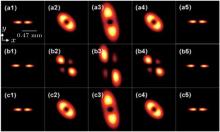
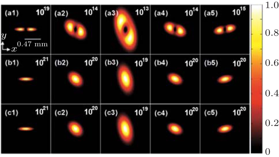
In Fig. 1, panels (a1) and (a2), (b1) and (b2), and (c1) and (c2) are propagating in RHM; while panels (a4) and (a5), (b4) and (b5), and (c4) and (c5) are REGBs propagating in LHM, with nL = − 1, − 0.8, − 0.5, respectively. Panels (a3), (b3), and (c3) are the intensity distributions in the interface of RHM and LHM. In this plane, the beam changes from divergence to convergence, the rotation direction changes from clockwise (positive direction) to counterclockwise (negative direction). The shape of the beam in LHM is similar to that of REGBs propagation in the ordinary medium. B in Δ affects the rotation, when B = 0, the beam back to the original position, B > 0 for the clockwise direction compares the original station, B < 0 for counter-clockwise direction compares the original station. When nL = − 1, after the REGB propagates the same length as in RHM (B = 0), the rotation angle changes from + π /2 to 0, back to the original station, the optical pattern is the same as that in RHM comparing panels (a1), (a2) with panels (a4), (a5) in Fig. 1. That is, LHM acts as a perfect lens for REGB beams.[2] It means that the intensity distribution is the symmetry of the interface for nL = − 1. When nL = − 0.8, after the REGBs propagate 0.16 m in LHM (B = 0), the rotation angle changes to 0 and the intensity distribution is the same as that of panel (b1). In this process, the beam converges all the time. After this position, the beam continues rotating counterclockwise and begins to diverge again. When nL = − 0.5, at the position of L = 0.1 m in LHM (B = 0), the beam intensity distribution of panel (c4) is the same as that of panel (c1). The rotation angle of panel (c4) is 0 in comparison with panel (c1), but − π /2 comparing panel (c3). After it propagates to L = 0.2 m, the rotation angle is approximately − π /2 comparing panel (c1), but − π in comparison with panel (c3).
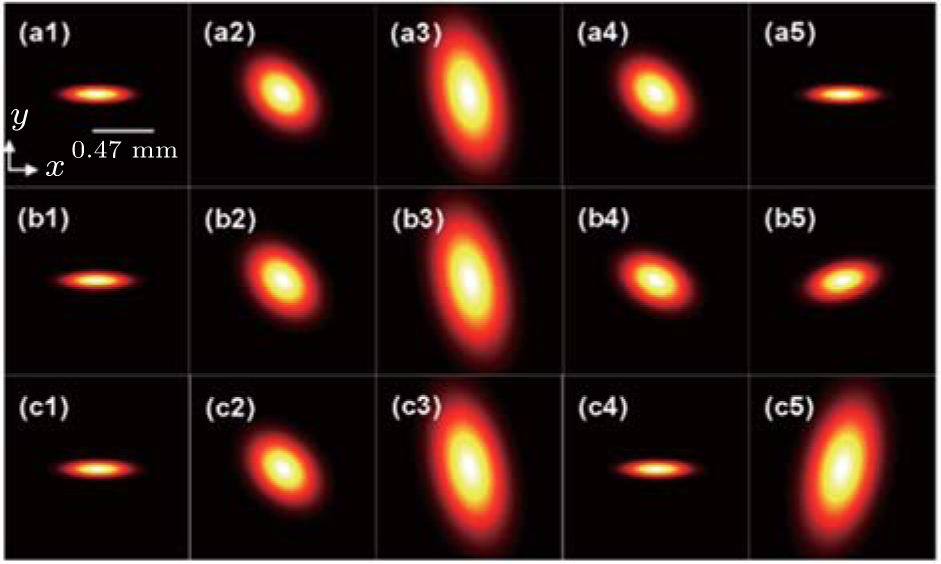 | Fig. 1. Intensity distributions of REGB during the propagation from RHM to LHM for different refractive indices of LHM. (a1)– (a5) nL = − 1; (b1)– (b5) nL = − 0.8; (c1)– (c5) nL = − 0.5. In panels (a1), (b1), and (c1), z = 0. In panels (a2), (b2), and (c2), z = 0.1 m. In panels (a3), (b3), and (c3), z = 0.2 m (L = 0). In panels (a4), (b4), and (c4), L = 0.1 m. In panels (a5), (b5), and (c5), L = 0.2 m. |
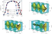
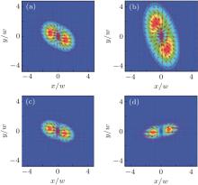
Figure 2(a) gives the absolute value of the rotation angle for different nL with the total propagation distance. Z is z + L in Fig. 2. As the figure shows, the absolute value of the rotation angle is approximately 90° as the propagation distance is long enough in RHM or LHM (comparing Z = 0). After propagating 0.4 m in RHM (rotation angle is + 90° ), one can see that the rotation angle in LHM changes about − 90° , − 105° , and − 180° for nL = − 1, − 0.8, and − 0.5, respectively, while the propagation distance is Z = 0.8 m (comparing Z = 0.4 m). In LHM, when the rotation angle is 0° (compares Z = 0) or − 90° (comparing Z = 0.4 m), Z = 0.6 m for nL = 0.5, Z = 0.72 m for nL = − 0.8, Z = 0.8 m for nL = − 1. Larger nL changes the same rotation angle for shorter propagation distance, the rotation velocity gets faster and faster as the nL increases with the same propagation distance. From this point, the rotation velocity gets faster and faster as the nL increases with the same propagation distance. The maximum rotating angle of the beam is + 90° in RHM (Z = 0.4 m comparing Z = 0), − 90° in RHM (Z = 0.8 m comparing Z = 0). When the propagation distance in the LHM is long enough, the rotation angle tends to change − 180° for different nL (comparing Z = 0.4 m).
 | Fig. 2. (a) The absolute value of the beam rotation angle as a function of the total propagation distance. In RHM, Z = 0 to 0.4 m. In LHM, Z = 0.4 m to 0.8 m. (b)– (d) Three-dimensional (3D) intensity distributions of REGB propagating through three groups of RHM and LHM. (b) nL = − 1; (c) nL = − 0.8; (d) nL = − 0.5. The parameters are the same as those in Fig. 1. |
For better understanding the propagation of REGBs in LHM and RHM, we consider three groups of RHM and LHM as shown in Figs. 2(b)– 2(c). For nL = − 1, as mentioned before, the intensity distribution is the symmetry of the interface. So that the intensity distribution finally forms the periodic structure as shown in Fig. 2(b). The beam tends to converge firstly and then diverges as the propagation distance increases with nL = − 0.8 in Fig. 2(c). In Fig. 2(d), the nL is − 0.5, the beam pattern tends to diverge as the propagation distance increases. In fact, if we choose the thickness of LHM as 0.16 m for nL = − 0.8, 0.1 m for nL = − 0.5, the beam can also form the periodic structure, so the propagation properties of REGBs are not only related to nL, but also related to the thickness of the medium and we can choose proper nL and the thickness to produce a worthy propagation pattern such as figure 2(b) shows.
The local energy flow is usually expressed in terms of the Poynting vector. The Poynting vector has a magnitude of energy per unit area (or per unit time), and a direction which represents the energy flow at any point in the field. The Poynting vector is defined as S = (c0/4π ) E × B.[29] The vector potential is a linear polarization state. Given an x̂ -polarized vector potential A = ê xΦ (x, y, z)exp(ikz), where ê x is the unit vector along the x direction. The time-averaged Poynting vector can be expressed as[10]
where ∇ ⊥ = (∂ /∂ x)ê x + (∂ /∂ y)ê y, ê y and ê z are the unit vectors along the y and the z directions, respectively. c0 is the velocity of light in a vacuum, E and B are the electric and the magnetic fields, respectively, and * denotes the complex conjugate. Substituting Eq. (5) into Eq. (6), we can get the components Sx, Sy, and Sz as follows:


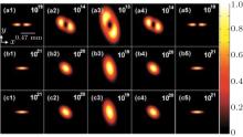
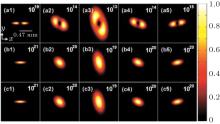
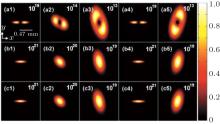
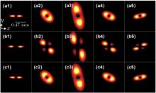
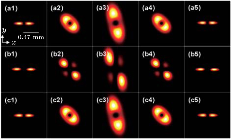
Figures 3– 5 are the energy flow distributions based on Eqs. (6)– (8). As can be seen from Figs. 3– 5, for a given nR and nL, the beam propagating patterns are stable, except that the overall scale changes, as does the pattern rotation as a whole with z increasing. The rotation direction of the energy flow is the same as that of the light intensity. The transverse distribution of the energy flow for nL = − 1, − 0.8, − 0.5, as shown in panels (a1)– (a5) in Fig. 3, panels (a1)– (a5) in Fig. 4, and panels (a1)– (a5) in Fig. 5, tends to be in both ends of the ellipse like a dumbbell. However, in the z direction it concentrates in the middle and keeps the shape of the ellipse. For the total energy flow, the distribution is also elliptical that is the same as the z direction component. On the other hand, transverse contributions are much greater than z components on the order of magnitude. It means the impact of the energy flow of the z direction component is greater than that of the transverse component.
 | Fig. 3. Poynting vectors of REGB propagating through three groups of RHM and LHM with nL = − 1. Panels (a1)– (a5) are the transverse components, panels (b1)– (b5) are the z-direction components, panels (c1)– (c5) are the total energy flow. The parameters are the same as those in Fig. 1. |
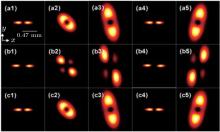
 | Fig. 4. The same as those in Fig. 3 except for nL = − 0.8. |
 | Fig. 5. The same as those in Fig. 3 except for nL = − 0.5. |
It is obvious that the distribution of the energy flow propagating from RHM to LHM should correspond to the intensity distribution of the beam. So that the energy flow tends to diverge in RHM and converges firstly then diverges in LHM. In this process, the rotation direction and the rotation velocity of the energy flow are the same as those of the light intensity.
In Fig. 6, for a given refractive index, the Poynting vector flow rotates as a whole, the direction and the magnitude of the arrows agree with the direction and the magnitude of the energy flow in the transverse plane. The Poynting vector flow is initially clockwise and turns counterclockwise as the refractive index becomes negative. It is interesting to see that the vector direction is opposite when B changes from positive to negative. The change in the Poynting vector can be used to explain the physics behind the rotation phenomenon of the beams as the inhomogeneity of the energy flow within the beam cross section.[12]
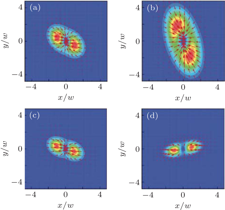 | Fig. 6. Transverse energy flow (background) and transverse energy flow direction (red arrows) for REGB propagating through RHM and LHM with nL = − 0.8. In panel (a), z = 0.1 m. In panel (b), z = 0.2 m (L = 0). In panel (c), L = 0.1 m. In panel (d), L = 0.2 m. The parameters are the same as those in Fig. 1. |
Since Poynting first considered a circularly polarized beam, the AM of light has been studied by an analogy with the mechanical properties of a revolving shaft.[30] The AM carried by a beam of light often plays a significant role in the light– matter interaction. As in mechanics, the time-averaged AM density for the electromagnetic field is the AM per unit area (per unit time), obtained by forming the cross product of the position vector with the time-averaged momentum density P ∝ E × B, [31]

where jx = 2yk| Φ | 2 − izSy, jy = izSx − 2xk| Φ | 2, and jz = i (xSy − ySx).
Figures 7– 9 give the images of Eq. (10) for nL = − 1, − 0.8, − 0.5, respectively. Comparing Figs. 7– 9, one can also obtain that for different nL, the AM distribution patterns are stable, except that the overall scale changes, as does the pattern rotation as a whole with z increasing.
 | Fig. 7. AM of REGB propagating through three groups of RHM and LHM with nL = − 1. Panels (a1)– (a5) are the transverse components, Panels (b1)– (b5) are the z direction components. Panels (c1)– (c5) are the total AM density. The parameters are the same as those in Fig. 1. |
 | Fig. 8. The same as those in Fig. 7 except for nL = − 0.8. |
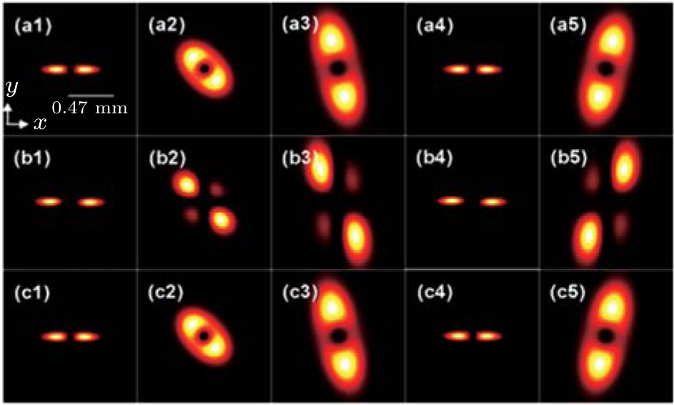 | Fig. 9. The same as those in Fig. 7 except for nL = − 0.5. |
It is interesting to see that not only do the transverse but also the z-direction AM components look like dumbbells. In fact, from the AM equation j = r × S, we can find that the AM depends on S and r. As r is related to the coordinate, the shape of AM should be similar to S. But r will still affect AM, so the z-direction and the transverse direction components have some differences from the Poynting vector’ s. It is not difficult to see that the rotation direction, the rotation velocity, and the evolution of AM are the same as those of the energy flow. But not like the energy flow, the total intension distribution of AM is more like that of the transverse component. That means the impact of the transverse AM is greater than that of the z-direction component.
In conclusion, based on the ABCD matrix, the propagation properties of REGBs through RHM to LHM systems are investigated. The study shows that REGBs have opposite characteristics when transmissions happen in RHM and LHM. Generally speaking, the beam intensity usually diverges in RHM and converges firstly then diverges in LHM. The beam rotates clockwise in RHM while counterclockwise in LHM. For a short propagation distance, the rotation velocity increases as nL increases, but for a long distance, the average rotation velocity tends to be equal for different nL. Based on the propagation properties in RHM and LHM, the REGBs propagating in three sets of RHM and LHM can form different propagation patterns, such as the periodic structure. As the basic characteristic parameters of the beam, the energy flow, and the AM have the same evolution regulation with the light intensity. However, the impact of the transverse component of the energy flow is greater than that of the z-direction component while the AM is opposite.
| 1 |
|
| 2 |
|
| 3 |
|
| 4 |
|
| 5 |
|
| 6 |
|
| 7 |
|
| 8 |
|
| 9 |
|
| 10 |
|
| 11 |
|
| 12 |
|
| 13 |
|
| 14 |
|
| 15 |
|
| 16 |
|
| 17 |
|
| 18 |
|
| 19 |
|
| 20 |
|
| 21 |
|
| 22 |
|
| 23 |
|
| 24 |
|
| 25 |
|
| 26 |
|
| 27 |
|
| 28 |
|
| 29 |
|
| 30 |
|
| 31 |
|