

Multi-mode coupling analysis of a sub-terahertz band planar corrugated Bragg reflector*
[Liu Guo , Luo Yong, Wang Jian-Xun, Shu Guo-Xiang]
, Luo Yong, Wang Jian-Xun, Shu Guo-Xiang]
|
|


†Corresponding author. E-mail: liuguo.uestc@gmail.com
*Project supported by the National Natural Science Foundation of China (Grant No. G0501040161101040).
Planar Bragg reflector operating in the sub-terahertz wavelength installed at the upstream end of a sheet beam backward wave oscillator (BWO) is very promising to minimize the whole circuit structure and make it more compact. In this paper, a sub-terahertz wavelength (0.18–0.22 THz) tunable planar Bragg reflector is numerically analyzed by using multi-mode coupling theory (MCT). The operating mode TE10 and dominant coupling mode TE01 are mainly considered in this theory. Reflection and transmission performance of the reflector are demonstrated in detail and the results, in excellent agreement with the theoretical analysis and simulation, are also presented in this paper. Self- and cross-coupling coefficients between these two modes are presented as well. The reflector behaviors with different Bragg dimensions are discussed and analyzed in the 0.16–0.22 THz range. The analysis in this paper can be of benefit to the design and fabrication of the whole BWO circuit.
In the millimeter and sub-millimeter wavelength band, reflectors based on the Bragg coupling of counter-propagating waves in the periodic structures can provide a frequency selective feedback for overmoded high-power oscillators such as the cyclotron auto-resonance maser (CARM), [1– 3] free electron laser (FEL), [4] gyrotron backward wave oscillator (BWO), [5] and terahertz (THz) BWO.[6] The periodically corrugated waveguides composed of the reflector can provide a high reflectivity through the principle of constructive interference, allowing the formation of a frequency selective resonator with effective electron beam transportation. A forward wave is coherently scattered into a reflected wave due to the cascaded corrugations. Superposition of multi-waves leads to a high reflectivity when the Bragg resonant condition (kb = 2k, k is the axial propagation constant, kb = 2π /d, and d is the corrugation period) is satisfied.
For a BWO or gyro-BWO, [5– 7] the oscillation signal will be collected in the upstream end on the gun side due to the properties of the backward wave. Thus, an energy extracting system must be connected between the high-frequency slow wave structure (SWS) and the electron gun, which increases the structural complexity in the design and fabrication. One solution to this issue is to reflect the output power to the downstream end near the collector by using a Bragg reflector and then radiate it from an axially aligned horn. Like the BWO’ s coupling system, an input coupler for travelling wave tubes (TWTs)[8] comprised of the Bragg reflector can achieve a relatively large beam tunnel and broad bandwidth compared to the coupler with a cutoff waveguide. This structure also allows electrons to have good transportation and the path to be unobstructed. The corrugated reflector herein under discussion is very promising for realizing the compact size and miniaturizing the sheet beam BWOs or TWTs in the THz range.
Generally, a corrugated Bragg resonator with a cylindrical cross section[1, 2, 4, 5] or coaxial structure[3, 9] is adopted in the CARM, FEL, and gyro-BWO. However, a sheet electron beam promotes the development of 2D radiation sources, [10– 12] where a planar Bragg reflector comprised of the symmetric periodic corrugations is of great importance for their design. A tunable planar narrow-band advanced Bragg reflector (ABR) based on the interaction between a propagating wave and a quasi-cutoff trapped wave is proposed by Ginzburg et al.[13, 14] However, the propagating mode injected into the reflector must be in the TEM mode, which is usually not consistent with the stimulated mode in the BWO or TWT. Furthermore, the ABR width of the overmoded corrugated waveguide is very large so that high order modes may be excited. Therefore, a planar conventional Bragg reflector is considered instead of the ABR. In this paper, a planar corrugated Bragg reflector for the sub-terahertz (0.18– 0.22 THz) BWO operation is demonstrated. The rest of this paper is organized as follows. In Section 2, the multi-mode coupling analysis is presented. Coupling equations of the mathematical and physical basis are derived. The formulation is similar to that for the cylindrical cross-section, and relevant reflector performances including the reflection, transmission rate and the coupling coefficients are updated by using the multi-mode coupling theory (MCT). In Section 3, an operating mode TE10 and a dominant coupling mode TE01 are considered. Numerical results obtained by the MCT and CST Microwave Studio (CST-MWS) are compared and their good agreement is achieved. Besides, performance based on different structural parameters is analyzed in detail and discussed, which can instruct our optimization, fabrication, and measurement in the next stage. In Section 4, conclusions are drawn from the present study.
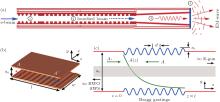
Figure 1(a) shows the diagram of the BWO. In order to reflect the BWO output signal to the downstream end and then radiate it by a launching horn, a reflector comprised of corrugated waveguides is designed. Three-dimensional (3D) modeling and basic geometry of the planar Bragg reflector are configured in Figs. 1(b) and 1(c), where the right-hand side (RHS) of the reflector connects with the planar electron gun (E-gun) and the left-hand side (LHS) connects with the BWO SWS. In this figure, A+ and A− , respectively, represent the forward and coupling backward wave, while A(z) denotes the exponentially decaying reflectivity or transmission rate. A+ is generated by the beam-wave interaction in the BWO SWS, and then propagates towards the upstream end of the BWO due to the property of the backward wave. In the reflector, A− is also excited due to the corrugated waveguide. Note that A− is reflected to the SWS and then overlaps with A+ when the Bragg resonant condition kb = 2k is satisfied, where 
 | Fig. 1. (a) Backward wave oscillator with Bragg reflector.  |
The coupled mode equations between A+ and A− can be described as[2, 13]
 |
Here, Bragg mismatch Δ = k − kb/2, α is the Ohmic dissipation loss constant (in the following discussion, we omit the influence from this item), and G is the wave coupling coefficient. Corrugations can couple one mode i to another mode j in the cavity if they satisfy the modified Bragg resonant condition
 |
The multi-mode coupling equation is
 |
where Gii, Gj j, and Gi j represent the self-coupling and cross-coupling coefficients of mode i and j, respectively. Let mode i represent a TE mode (H-mode) and mode j represent a TM mode (E-mode), then general equations will be extended to four first-order linear equations expressed in a vector form as
 |
where Δ H and Δ E are the Bragg mismatch factors of the TE and TM mode; GH, GE, and GX are the self-coupling coefficients of TE– TE and TM– TM, and cross-coupling coefficient of TE– TM, respectively.[2, 15]
For a planar Bragg reflector with the consistent corrugation width discussed in this paper, the general coupling coefficients are given by[16]
 |
where
 |
 |
The indices i and j are for the coupling modes TEmn (TMmn) and TEm′ n′ (TMm′ n′ ), respectively. In these equations, ɛ p = 1 when p ≠ 0 and ɛ p = 2 when p = 0. GE, GH, and GX are related to the geometry a0, a1, w, and mode indices. If the Bragg reflector operates in a single mode, the coupling coefficients of the second self-coupling and cross-coupling items in Eq. (5) will be 0, i.e., GE = 0 and GX = 0.
The field amplitude in the waveguide satisfies A ∝ eλ z, then equation (4) can be described as a compact matrix eigenvalue problem given by
 |
Here, matrix M is the first vector item on the RHS of Eq. (4); λ and e are its eigenvalues and eigenvectors, respectively; I is an identity matrix. Once the eigenvalues and eigenvectors are found, the amplitude vector A at any position in the reflector can be expressed as a linear combination of four eigenvectors
 |
where Ki is a constant satisfying the boundary condition. Boundaries at the reflector ends (z = 0 and z = l) for TE (TM) mode are

 |
Using the values of Ki solved by Eqs. (9) and (10), the total reflection coefficient R and total transmission coefficient T can be obtained by the combination of H- and E-mode (or H- and H-mode or E- and E-mode)
 |
where 


For our sub-terahertz BWO central frequency at 0.2 THz, the designed SWS width is 1.2 mm. For simplicity, the reflector corrugation width w is also chosen as the same dimension. To make sure that the e-beam emitting from the E-gun will not be pre-bunched in the Bragg reflector and the circuit length is not too long, the mean distance between the Bragg gratings is around the dimension of the width. Considering the incident wave TE10 mode determined by the BWO, odd high-order modes, such as TE30 and TE50, are not easy to generate because of the constant corrugation width. However, degenerated wave pairs TE10/TE01 may be produced because the constant width and mean distance of the gratings are very close to each other. For our square-like overmoded corrugated waveguide with weak ripples, the 1st– 2nd parasitic waves are TE01, TE11(TM11), and TE20. Two dominant modes TE10 and TE01 in the cavity controlling the reflector performance will be mainly discussed by using MCT in the following sections. With parameters of d = 1.0 mm, w = 1.2 mm, and a0 = 1.1 mm, the Bragg resonance criteria kTE10 + kTE01, kTE10 + kTE(TM)11, kTE10 + kTE20, and kb for the fundamental TE10 and another coupling mode are plotted in Fig. 2. Optimal Bragg resonant points are at 0.20 THz, 0.22 THz, and 0.26 THz, respectively.
 | Fig. 2. Bragg resonance criteria for two modes of TE10 and TE01, TE20 and TE11 (TM11), where kb is the Bragg resonant condition. |
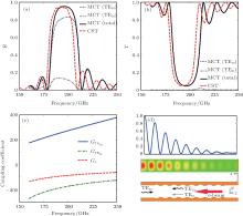
Table 1 shows a group of optimized parameters for the Bragg reflector working in a sub-terahertz band centered at 0.2 THz. Reflection, transmission performance, and self- and cross-coupling coefficients of the TE10, TE01, and the total combination rate obtained from MCT are demonstrated in Figs. 3(a)– 3(c). The total reflection and transmission rate obtained by CST-MWS[17] are also compared in the figures. Figure 3(d) also shows the total power contour plot and its normalized power flow. We can obverse that a maximum of 13.7% TE01 around 0.19 THz is coupled and reflected to the entrance. Total reflectivity and transmission are 0.95 and 0.05, respectively. The 3-dB bandwidths from the MCT scheme and CST-MWS are 28 GHz (0.183– 0.211 THz) and 26 GHz (0.180– 0.206 THz), respectively. The operating band obtained by MCT is 1%− 2% higher than that from CST-MWS, which is because in our theoretical analysis only the operating mode TE10 and a dominant coupling mode TE01 are included, but much higher-order modes are neglected. From our simulation, we find the suppression to the nearest higher-order modes except the TE01 is maintained at a very high level (> 130 dB). We can also find that the self-coupling coefficient GTE10 increases, but the self-coupling coefficient GTE01 and cross-coupling coefficient GX decrease with the band extending to higher frequencies. This reveals that the reflectivity in the reflector is mainly controlled by the TE10 mode, and this effect is enhanced with the increase of frequency.
| Table 1. Typical operating parameters of the Bragg reflector. |
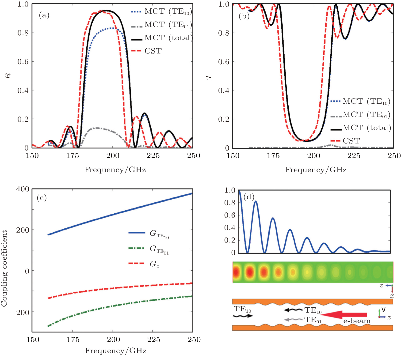 | Fig. 3. Numerical results calculated by MCT and CST-MWS: (a) reflectivity and (b) transmission of TE10, TE01, and their combination, (c) self-coupling and cross-coupling coefficients as a function of frequencies, and (d) power distribution function and contour plot along the axial distance at 0.2 THz. |
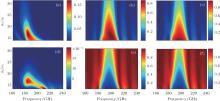
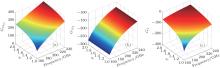
From our previous discussion and Eqs. (5)– (7), coupling coefficients are determined by the mode indices, corrugation width w, corrugation amplitude a1, and mean distance a0. Therefore, only the coupling coefficients relative to a1, a0, and w are studied in the following sections. The dependences of reflectivity, transmission, and coupling coefficients on various parameters can instruct the design, modelling, fabrication, and final tolerance assembled with our BWO slow wave structure. Figure 4 gives the reflection and transmission rates of TE10, TE01, and the total combination, respectively, in Figs. 4(a)– 4(f), each of which is a function of the operating frequency and a0/a1. Our investigation indicates the reflector performances studied here, resulting from a0 and 1/a1, have the same variation tendencies, thus we define a normalized factor a0/a1 to illustrate this situation. There are two different cases, i.e., the increasing a0 and reducing a1, resulting in the increase of a0/a1. For the former case, the increasing a0 leads to overmoded characteristics of the corrugated waveguide so that the TE01 mode is much easier to excite. Both of these cases form a relatively weak ripple amplitude, which could reduce the reflectivity and bandwidth. When increasing a0, the influence from the corrugations will be weakened and the corrugated waveguide evolves into a smooth waveguide, where TE10 has a very low conversion and couples with higher-order modes so that the reflector performance worsens. Figure 5 shows the relevant coupling coefficients, and one can see that the magnitudes of these coefficients reduce until they are close to zero with increasing a0/a1. This phenomenon is consistent with the scenarios in Figs. 4(c) and 4(f). For the distance a0 between the two corrugations, if it is too small, the beam cross section will be limited; however, if it is too large, the confined PPM will not have enough space. From these two figures, we can also know whether the BWO is updated to a wide band operation, and reducing a0 or increasing a1 can improve the bandwidth of the matching Bragg reflector.
 | Fig. 4. Reflectivities and transmissions each as a function of frequency and normalized parameter a0/a1. (a)– (c) Reflectivities of TE01, TE10, and the total combination; and (d)– (f) transmissions of TE01, TE10, and the total combination. |
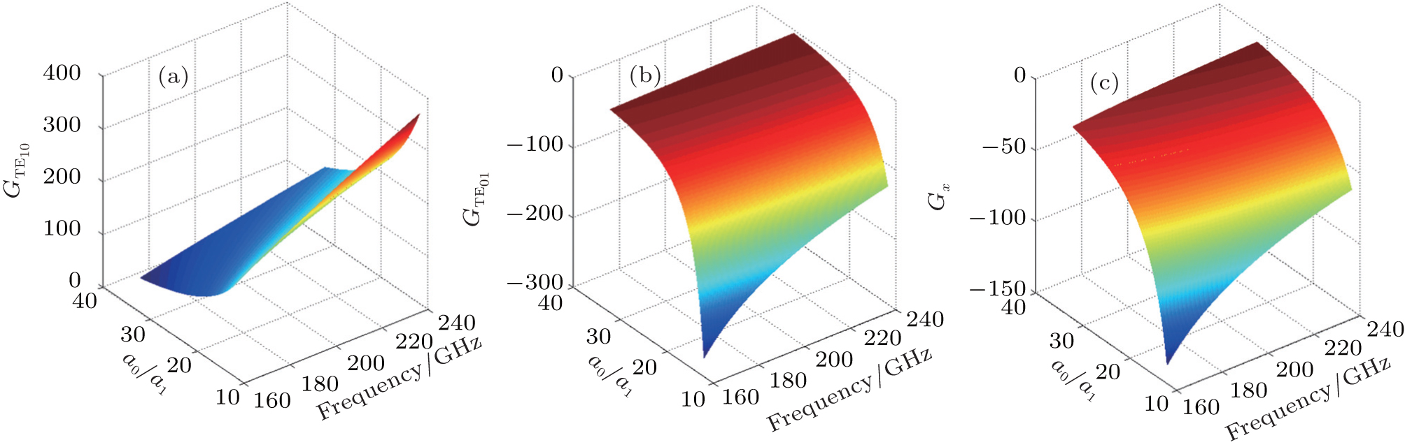 | Fig. 5. (a) Self-coupling coefficient GTE10, (b) self-coupling coefficient GTE01, and (c) cross-coupling coefficient GX versus frequency and a0/a1. |
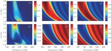
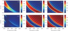
Figures 6 and 7, respectively, demonstrate the reflectivity, transmission rate, and coupling coefficients versus corrugation width w in the operating frequency range. When broadening w, operating bands of TE01, TE10, and their combination will shift to lower frequencies and meanwhile the bandwidth is greatly extended. This is because the increasing waveguide width results in a lower cutoff frequency. Note that in Figs. 6(a) and 6(d), reflection and transmission amplitudes of TE01 each have a concave region from w = 1.1 mm to 1.5 mm. Similar overmoded characteristics with the changing a0/a1 mentioned above occur here when changing w. Besides, the self-coupling coefficient GTE10 of TE10– TE10 increases, and GTE01 of TE01– TE01 remains unchanged, whereas cross-coupling coefficient GX between TE10– TE01 decreases. The sensitivity of the width to the reflector performance indicates that it is much easier to shift the operating band by adjusting w, but the problem is that the beam tunnel will be seriously affected.
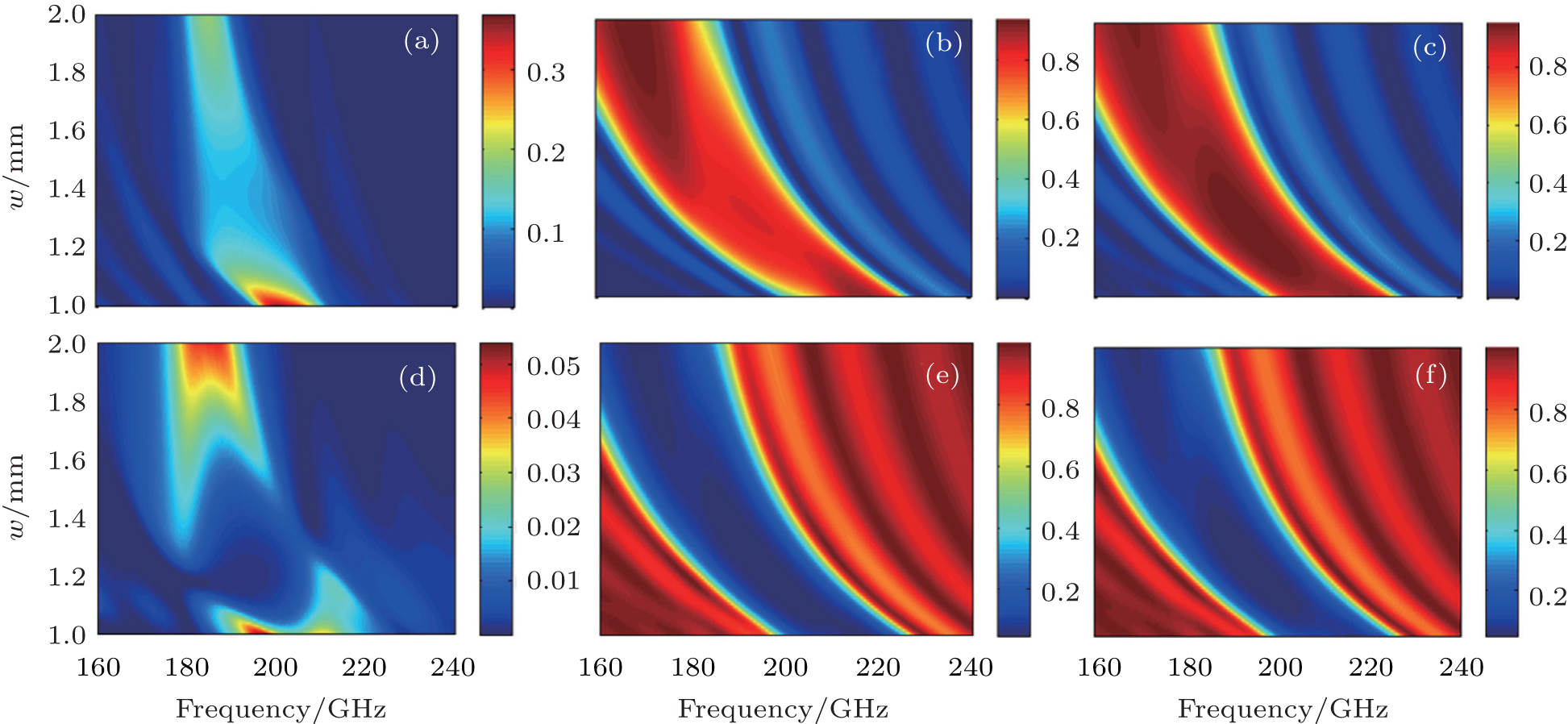 | Fig. 6. Reflectivities and transmissions versus corrugation width w. (a)– (c) Reflectivities of TE01, TE10, and the total combination; and (d)– (f) transmissions of TE01, TE10, and the total combination. |
 | Fig. 7. (a) GTE10 for TE10– TE10, (b) GTE01 for TE01– TE01; and (c) GX for TE10– TE01 versus frequency and w. |
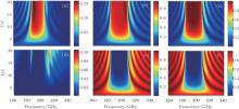
Figures 8 and 9 demonstrate the reflectivities and transmissions each as a function of corrugation period d and normalized reflector length l/d, respectively. The reflectivity (Fig. 8(a)) of TE01 increases up to 0.25 when extending the corrugation period to d = 1.5 mm, but the stop-band center is changed to 0.16 THz. Compared with the reflectivity, its transmission (Fig. 8(d)) in this case still stays at a very low level (less than 0.06). For the combined total reflection and transmission rate shown in Figs. 8(c) and 8(f), the whole operating range also shifts to lower frequencies with increasing d, accompanied by reducing the absolute bandwidth. In Fig. 9, the reflectivities of TE01 and TE10, respectively, concentrate in the lower and upper bands of the working range and the maximum proportions are ∼ 15% and 85%. Unlike the reflectivity, the proportion of TE01 contributing to the total transmission rate is very low in the stop band, and an interesting thing is that the maximum value (∼ 10%) emerges in the first side lobe but not the center. For the total reflectivity and transmission given in Figs. 9(c) and 9(f), the filtering stop bandwidth (0.18– 0.22 THz) does not change except for the magnitude. If we want to make sure that the reflectivity is over 0.95, the length of the reflector must be over 10 periodical Bragg corrugations. This conclusion can make us find the shortest reflector length so that the dimension of the whole BWO circuit is more compact in the engineering.
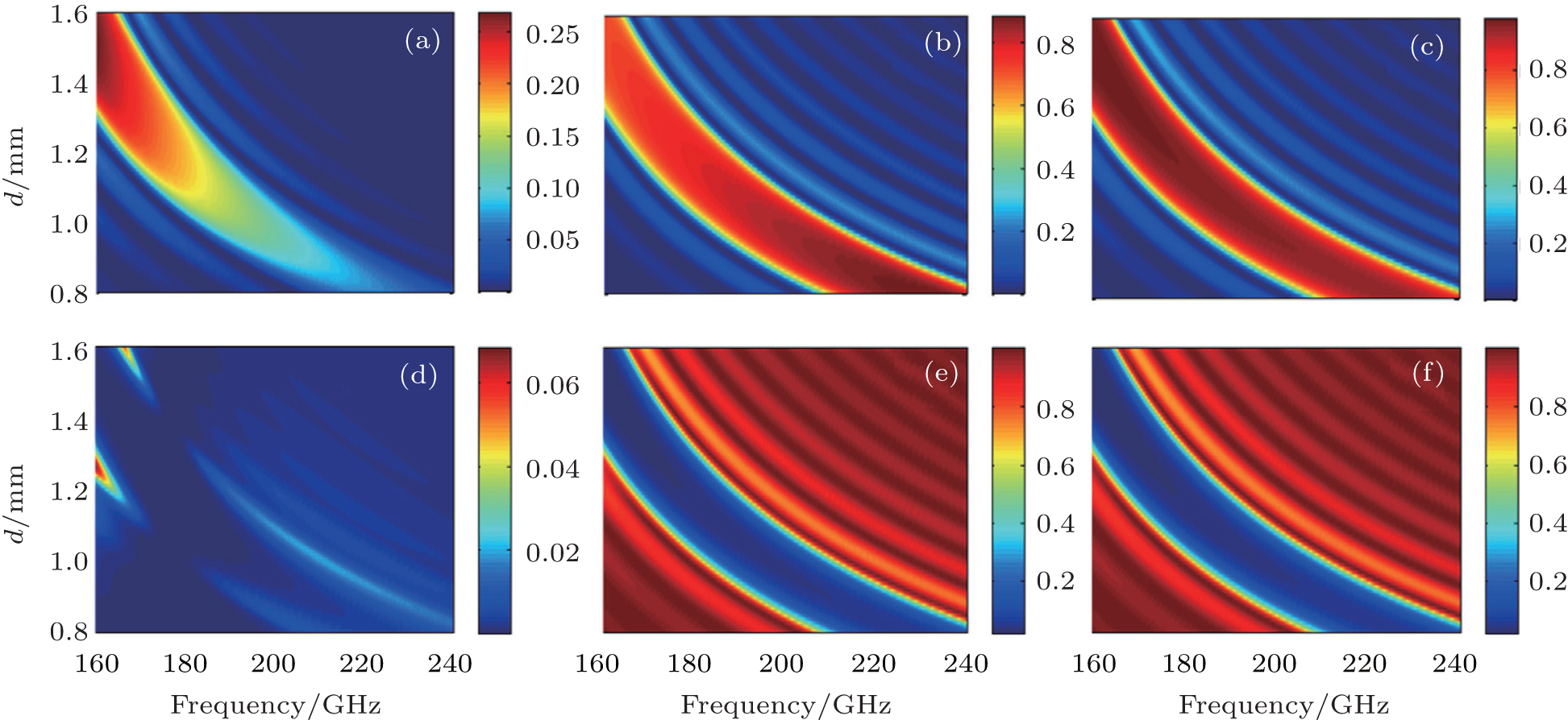 | Fig. 8. Reflection and transmission rates each as a function of frequency and corrugation period d. (a)– (c) Reflectivities of TE01, TE10, and the total combination; and (d)– (f) transmissions of TE01, TE10, and the total combination. |
 | Fig. 9. Reflectivities and transmissions versus frequency and normalized reflector length l/d. (a)– (c) Reflectivities of TE01, TE10, and the total combination; and (d)– (f) transmissions of TE01, TE10, and the total combination. |
Multi-mode coupling theory is derived and used to analyze a sub-terahertz wavelength (0.18– 0.22 THz) planar Bragg reflector, which is comprised of a periodical corrugated waveguide. It can benefit the compact design of sheet beam BWO or TWT as a promising component. A dominant mode TE10 and main coupling mode TE01 are considered in the MCT analysis. The reflector performance including reflectivity, transmission rate, and coupling coefficients calculated from MCT is examined and compared with the results obtained by CST– MWS, and good agreement is achieved. The influence of the structural dimension on reflector performance is demonstrated, which can instruct our final fabrication and assembly. The increases of a0/a1 and the number of Bragg cavities have no effect on the central frequency, but have great influences on the bandwidth and amplitude. Increasing the reflector width and period length would reduce the operating frequency. The bandwidth of the former case is extended, but the bandwidth of the latter one remains nearly unchanged.
| 1 |
|
| 2 |
|
| 3 |
|
| 4 |
|
| 5 |
|
| 6 |
|
| 7 |
|
| 8 |
|
| 9 |
|
| 10 |
|
| 11 |
|
| 12 |
|
| 13 |
|
| 14 |
|
| 15 |
|
| 16 |
|
| 17 |
|