


Spray forming and mechanical properties of a new type powder metallurgy superalloy*
[Jia Chong-Lina), b) , Ge Chang-Chuna)  , Xia Min
a) , Gu Tian-Fua) ]
, Xia Min|
|


†Corresponding author. E-mail: ccge@mater.ustb.edu.cn
*Project supported by the National Natural Science Foundation of China (Grant Nos. 50974016 and 50071014).
The deposited billet of a new type powder metallurgy (PM) superalloy FGH4095M for use in turbine disk manufacturing has been fabricated using spray forming technology. The metallurgical quality of the deposited billet was analyzed in terms of density, texture, and grain size. Comparative research was done on the microstructure and mechanical properties between the flat disk preform prepared with hot isostatic pressing (HIP) and the same alloy forgings prepared with HIP followed by isothermal forging (IF). The results show that the density of the spray-formed and nitrogen-atomized deposit billet is above 99% of the theoretical density, indicating a compact structure. The grains are uniform and fine. The billet has weak texture with a random distribution in the spray deposition direction and perpendicular to the direction of deposition. A part of atomizing nitrogen exists in the preform in the form of carbonitride. Nitrogen-induced microporosity causes the density reduction of the preform. Compared with the process of HIP+IF, the superalloy FGH4095M after HIP has better mechanical properties at both room temperature and high temperature. The sizes of the γ′ phase are finer in microstructure of the preform after HIP in comparison with the forgings after HIP+IF. This work shows that SF+HIP is a viable processing route for FGH4095M as a turbine-disk material.
Powder metallurgy (PM) superalloys have become the first choice of high-performance aircraft engine turbine-disk materials. They are characterized with an outstanding combination of uniform microstructure, fine grain, high-yield strength, and fatigue-resistant properties.[1] PM superalloys also have powder– particle boundaries (PPB), thermally introduced porosity (TIP), inclusions, and other defects due to their unique processing.[2, 3] Therefore, the quality of raw materials and processing parameters must be strictly controlled. However, these will lead to increased manufacturing costs and process complexity.[4]
Spray forming (SF) is an advanced quick-solidifying technology that stems from metal atomization and powder metallurgy. SF materials have fine microstructure and uniform composition characteristics similar to PM materials. Moreover, SF has overcome the disadvantages of PM, such as complicated processing and surface oxidation of powders.[5, 6] Nowadays, SF has become a hotspot in the development and application of advanced materials.[5] It has great potential in lowering the cost and shortening the process of manufacturing superalloy turbine disk blanks after casting/wrought and powder metallurgy.[6]
In recent years, most researches on spray-formed superalloy have been carried out.[7– 15] However, researches on spray forming around the PM superalloy are so far, not deep enough and systematic. For instance, the thermal deformation behavior and the microstructure characteristics of the spray-formed PM superalloy were studied by Zhang et al.[16– 18] The fatigue behavior of spray-formed PM superalloy was studied by Xu et al.[19] The theoretical modeling of the spray-forming process are carried out by Mi.[20] Therefore, it is very necessary to further study spray-formed PM superalloy, especially to study the mechanism of the relationship between the microstructure and mechanical properties of the spray-formed PM superalloy. Furthermore, there are still basic questions on the PM superalloy deposited billet that need to be clarified. For example, will spray-forming texture appear in the preform? If the texture appears, how would it influence the properties of the material? What is the effect of atomizing gas on the deposited billet’ s quality and what form does gas exist in? How does one choose the subsequent reasonable path of thermal technology to obtain the optimal mechanical properties of the spray-formed PM superalloy?
To address these questions, we study the superalloy FGH4095M, a new type of high-performance PM superalloy that is mainly used in manufacturing aeroengine turbine disks. The alloy is designed by the addition of trace element magnesium based on the composition of FGH4095 alloy.
In this paper, spray-forming technology is used to prepare an ingot of FGH4095M turbine disk superalloy. The metallurgical quality of the FGH4095M alloy deposited billet is evaluated in terms of relative density, texture, grain morphology and shrinkage porosity. Moreover, the contrastive study on the microstructure and mechanical properties of the FGH4095M alloy is carried out under two kinds of processing conditions: (i) spray forming + hot isostatic pressing (SF+ HIP) and (ii) spray forming + hot isostatic pressing + isothermal forging (SF+ HIP+ IF). The purpose of this study is to provide technical support and theoretical guidance for improving and optimizing the spray-forming process of the FGH4095M alloy and for determining the reasonable manufacturing process route of turbine disks.
The master alloy of FGH4095M was prepared in Fushun Special Steel Shares Co., Ltd using vacuum induction melting (VIM) followed by vacuum arc remelting (VAR). The SF of the deposited billet was conducted on an SK2 spray-forming device at the University of Bremen. The spray-formed preform has a diameter of 185 mm to 192 mm and a height of 262 mm. The main chemical composition of FGH4095M deposited billets (mass fraction, %) was C 0.03, Cr 12.1, W 3.8, Mo 3.7, Co 8.5, Al 3.6, Ti 2.5, Nb 3.5, and Ni Bal. High-purity nitrogen was used as the atomizing gas. The main spray-forming parameters were as follows: atomization pressure 3.5 Pa, scanning frequency 15.2 Hz, and initial spray distance 430 mm.
Samples for density, grain size, and texture analysis were cut from the preform using a line-cutting machine. Texture analysis was conducted on spray-formed superalloys. Mults cut from the preform were processed by hot isostatic pressing (HIP) directly. Two of the ‘ HIPed’ preforms were isothermally forged to produce pancake-shaped forgings with about 210 mm in diameter and 40 mm in height. Forgings were done at the Guizhou Anda Aviation Forging Co., Ltd. The ‘ HIPed’ flat preform and forgings were solution heat treated at 1120 ° C for 1 h with oil quenching, and aged at 870 ° C for 1 h with air quenching and then at 650 ° C for 24 h with air quenching. Standard mechanical tensile tests were carried out at room and high temperatures. The microstructure of the alloy and the typical morphology of precipitated phases were investigated using optical microscopy and scanning electron microscopy.
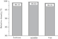
The specimens of the spray-formed FGH4095M were taken from the top, middle, and bottom parts of the deposited billet. The Archimedes method was used to measure the density of the sample. The theoretical density of FGH4095M alloy is 8.27 g/cm3. Thus, it is easy to compute the relative density of the specimens in different parts of the billet, which can reflect the densification state of the different parts of the deposited billet. The measurement results of the SF billet are shown in Fig. 1.
 | Fig. 1. Density of the FGH4095M deposited billet. |
Figure 1 shows that the distribution of the density of FGH4095M deposited billet is inhomogeneous. Density is associated with different parts of the deposited billet. The relative density of the central part is the highest, while that of the top part is the lowest. The average of the density of three parts of the FGH4095M spray-deposited billet is higher than 99%, that means a porosity of < 1%. For the deposited billet after HIP, the densification degree improves with a density of close to 100%.
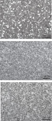
All the three parts of the deposited billet exhibit uniform and fine equated grains as shown in Fig. 2, in contrast to the coarse casing microstructure of superalloys. The morphology shows remarkably spherical or quasi-spherical grains and the grain size in the range of l0 μ m to 40 μ m, with an average grain grade of about ASTM 7∼ 8. From the top part to the bottom part of the deposited billet, grains become finer and the number of spherical grains increase. The change of grain size and the morphology of the different parts of the deposited billet are closely related to heat transfer during the deposition process. The top of the deposit billet is the hottest part during cooling, thus becoming the final solidification zone. Therefore, its rate of solidification is the slowest and its grain growth has sufficient thermodynamic conditions. As a result, in this part it has the largest grain size. In general, the difference in grain size in each part of the preform is little.
 | Fig. 2. Grain morphology of the spray-formed FGH4095M billet. (a) Bottom, (b) central, and (c) top. |
Observation shows that different parts of the FGH4095M deposited billet have weak texture with a random distribution. The texture density in the spray deposition direction and perpendicular to the direction of jet deposition is very weak. The maximum density of the texture in each direction is only 1.5. The ODF constant ψ profiles of the central part of spray formed billet are shown in Fig. 3. The ODF constant ψ profiles of the top and bottom deposition billets do not have any difference. The texture of the deposited billet in the direction of deposition mainly contains 


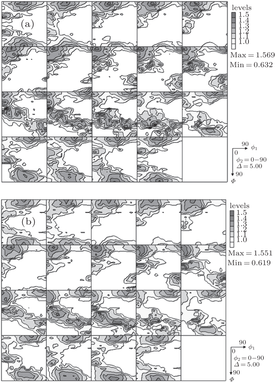 | Fig. 3. Constant ψ -sectional view (Δ ψ = 5° ) of the ODF of the central part of the billet: (a) direction of deposition and (b) vertical to the direction of deposition. |
The texture is the result of the preferred grain orientation. Spray forming is accompanied by crystallization and solidification of the molten droplet. Crystallization is the process of generation and growth of the crystal nucleus. As the organization of the equiaxed grains occurs mostly in the process of spray forming (Fig. 2), this shows that crystal nuclei are generated and grown randomly and uniformly by and large. Thus, texture should not exist in spray-formed organization after crystallization. However, the heat of the deposited billet dissipates inevitably from a certain direction because droplets have been deposited to produce a specific shape blank owing to the structure and form of the movement of the atomization nozzle. The directional dissipation of heat resulted in the formation of a temperature gradient field in the deposited billet. It also promotes that the crystal nuclei are generated preferentially in the low-temperature region. Then, the oriented growth of crystal nuclei occurs along the temperature gradient vector to the high temperature zone. Crystal nuclei are led to selective growth because of the promoting effect of the temperature field on the growth of the crystal nucleus so that a loose texture is formed eventually in the deposited billet.[21– 23]
The reasons for the texture formation are that the temperature gradient field is formed through directional transmission and dissipation of heat during spray forming so that the grain growth of the preferred orientation occurs during deposition, crystallization, and solidification.
The texture of spray-formed superalloy is so weak that it will barely impact the performance of the alloy. This reflects the advantages and uniqueness of the spray-forming process.
The nitrogen contents in the different parts of the deposited billet and in the master alloy bars are given in Table 1. Higher nitrogen contents are in different parts of the deposit after SF. This can be attributed to the wrapping of a part of the atomizing gas into the deposited preform during spray forming. From the analysis, it was found that a portion of the atomization nitrogen in the preform exists in the form of carbonitride. As the atomized droplets were deposited at high temperature, complex physical and chemical reactions occurred. Therefore, a part of nitrogen exists in the form of carbonitride. Figure 4 shows the carbonitride morphology of the FGH4095M preform. Also in Fig. 4, the white lumps (see arrows) are carbonitrides. On the whole, carbonitride is dispersed in the matrix. Square particles dispersed around the carbide are the γ ′ phase.
| Table 1. Nitrogen contents of the FGH4095M alloy before and after spray forming. |
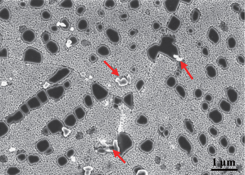 | Fig. 4. Carbonitride of the spray-formed FGH4095M billet. |
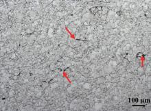
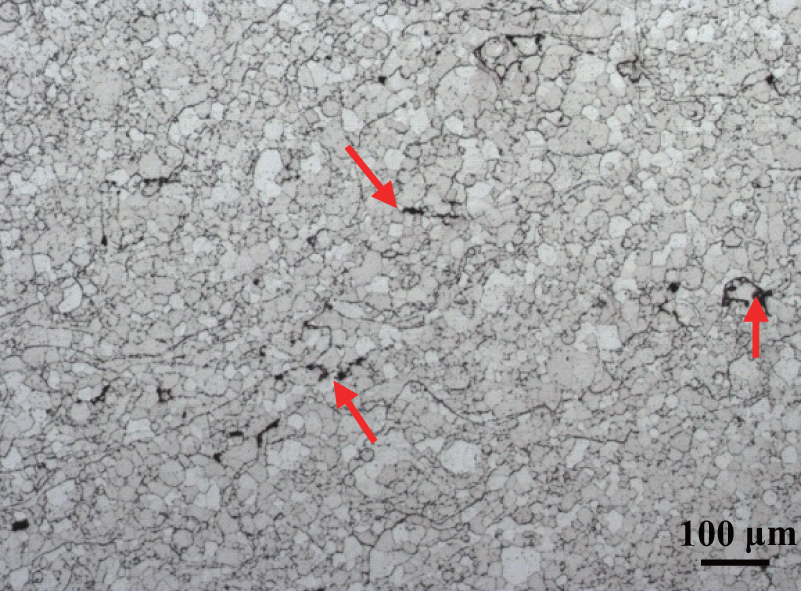
Observation shows that a few areas on the FGH4095M deposited billet are loose and porous, with the loosest texture at the top part. During spray forming, the solidification speed is slower in the central region, which has the hottest part, than in the surface region. Part of the residual gases gathered at the final solidification zone, which may be attributed to the loosest area gathering on the top part of the billet, i.e., the final shrinkage region on the liquid superalloy. The porous morphology of the top part of the FGH4095M deposited billet is shown in Fig. 5 (arrows pointing to the pores).
 | Fig. 5. Porous morphology of the top part of the FGH4095M deposited perform. |
On the other hand, the density of the deposited billets is closely related to the porosity and gas content of the deposited billet. Nitrogen exists mainly in the form of dispersed carbonitride in deposited billets (see Fig. 4), and a small part of the nitrogen is in the form of N2 which causes the deposited billet to be porous. Although the content of nitrogen in the top part of the deposited billet is relatively low (180 ppm), the top has the worst loose image (Fig. 5) and the lowest density (Fig. 1).
The reasons for the porosity in spray-formed superalloys are the following: (i) high-temperature liquid metal is smashed by high-velocity gas, forming hollow droplets and hollow powders which enter the deposited billet with absorbed atomizing gas on the surface of the droplets; (ii) the crossover packing of atomized droplets generates a void and there is insufficient liquid to fill; (iii) the gas leads to cavities when the solubility decreases in the process of solidification for the deposited billets. Generally, due to the surface tension force, the cavities of deposited billets are spherical and mainly distributed in the interior of the billet, especially in the region of the final step of solidification. The cavities distribute in the grain boundaries or the triangle regions between the grain boundaries and their size and distributions are affected by the condition of solidification. The higher the liquid content in the deposition surface, the slower the solidification rate, leading to larger cavities of the billet.[24, 25]
Therefore, we should take effective measures to reduce the loose areas in the atomized billet related to gas and the amount of residual gas. To increase density, residual gas can also exist in the formation of dispersed microporosity without aggregation through the strict control of parameters during deposition. It is most important to point out that subsequent hot isostatic pressing and hot deformation process can eliminate the microporosity and cavities in the billet.
After the same heat treatment, mechanical properties of the superalloy FGH4095M under two kinds of process conditions of spray forming + hot isostatic pressing (SF+ HIP) and spray forming + hot isostatic pressing + isothermal forging (SF+ HIP+ IF) are shown in Table 2.
| Table 2. Mechanical properties of the superalloy FGH4095M prepared using different processes. |
The experimental results in Table 2 show that at room temperature, the mechanical properties of the preform prepared by SF+ HIP are higher than the Aviation Standard requirement. The ‘ HIPed’ preform has good tensile strength, yield strength, and plasticity. The tensile strength (1380 MPa) and elongation (6.7%) of a sample from forgings prepared by SF+ HIP + IF do not reach the specified value of the Aviation Standard. The mechanical average properties of tensile strength, yield strength, elongation and reduction of area for the FGH4095M deposited preform prepared by HIP are superior to those of the FGH4095M forgings prepared by HIP+ IF in general.
In addition, Table 2 shows that at 650 ° C, the mechanical average properties of FGH4095M ‘ HIPed’ preform are superior to those of the FGH4095M forgings, although both the mechanical tensile properties of FGH4095M ‘ HIPed’ preform and those of FGH4095M forgings are above the Aviation standard. It should be stressed that compared with the FGH4095M forgings, the FGH4095M ‘ HIPed’ preform has an excellent toughness with relatively higher strength.
Thus, the mechanical properties for the FGH4095M deposited preform prepared by ‘ HIPed’ treatment are superior to that of FGH4095M forgings prepared by ‘ HIPed’ and IF treatment.
Gamma prime is the main strengthening phase of the FGH4095M alloy. The number, size, morphology, and distribution of the γ ′ phase affect the mechanical properties of the alloy. Figure 6 shows the relationship between the γ ′ phase and precipitation temperature in FGH4095M alloy calculated by JMatPro software. Figure 6 also shows that the total number of γ ′ phase is about 55% (mole fraction) and the solution temperature of γ ′ phase is about 1150 ° C.
 | Fig. 6. Relationship between γ ′ phase and precipitation temperature in the FGH4095M alloy calculated by JMatPro. |
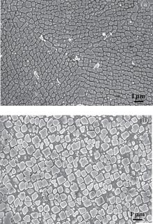
The morphology of the γ ′ phase of the ‘ HIPed’ preform and forgings after the same heat treatment are shown in Fig. 7. Many γ ′ phase precipitations exist in the microstructure of the ‘ HIPed’ preform because the HIP treatment temperature was lower than the solution temperature of 1150 ° C of the γ ′ phase so that the γ ′ phase is not completely dissolved. After solution treatment at a temperature of 1120 ° C, there were still some primary γ ′ phases. Large amounts of dispersed secondary γ ′ phases and a small amount of fine tertiary γ ′ phases were precipitated after the aging treatment. The gamma prime distribution consists of primary γ ′ phase less than 1 μ m, secondary γ ′ phase of about 0.3 μ m, and tertiary γ ′ phase of about 40 nm (Fig. 7(a)).
 | Fig. 7. Morphology of the γ ′ phase of the superalloy for the (a) ‘ HIPed’ preform and (b) forgings. |
Moreover, figure 7(b) shows that there are still many precipitated γ ′ phases in the microstructure of forgings after heat treatment. As deformed recrystallization occurs in the process of isothermal forging, the grain size becomes finer. However, the cooling rate of the forgings is slow after isothermal forging, and so the retained primary γ ′ phase coarsens relatively. After heat treatment, the γ ′ precipitates mainly include some primary γ ′ phases of about 1 μ m, a large amount of secondary γ ′ phase of about 0.6 μ m, and a small amount of the tertiary γ ′ phase about 50 nm. Thus, the average size of the γ ′ phase is bigger compared with those of the ‘ HIPed’ preform.
The strengthening mechanism of the alloy is that a dislocation crosses the gamma prime by the cutting mechanism or by the Orowan bypassing mechanism because the tensile test was carried out under high stress conditions, and meanwhile the deformation rate was fast.[26– 28] There is a critical size for gamma prime. When the γ ′ particle size is smaller than the critical size, the dislocation cross γ ′ particle by the cutting mechanism, and when the γ ′ particle size is greater than the critical size, the Orowan mechanism plays a major role.
The secondary γ ′ particle of the superalloy FGH4095M is the main strengthening phase. The average size of the secondary γ ′ particle is far greater than 100 nm (Fig. 7). Hence, the dislocation cross γ ′ particle by the Orowan mechanism. In this mechanism, the increment of yield strength can be described by
 |
 |
where Δ τ is the increment of yield strength, G is the shear modulus, b is the length of the Burgers vector, v represents a Poisson, and L is the average distance between the edge of the two particles.
It can be seen from Eq. (1) that the increment of yield strength is related to the average distance between the particles. The smaller the particle spacing, the greater the yield strength. Therefore, the yield strength of the FGH4095M deposited preform prepared by ‘ HIPed’ treatment are higher than that of FGH4095M forgings prepared by ‘ HIPed’ and IF treatment as the former has smaller γ ′ particle spacing in the microstructure. That is to say, when the size of the γ ′ particle in the alloy exceeds the critical size, the larger the size of the γ ′ particle is, the lower the mechanical properties of the alloy are.[29, 30]
In brief, the above preliminary research work shows that it is a promising route to adopt the SF+ As-HIP process for manufacturing turbine disks.
i) The density of spray-formed and nitrogen-atomized deposited billet, which has compact structure, is above 99% on average. The microstructure of the grain is uniform and fine.
ii) The billet has weak texture with a random distribution in the spray deposition direction and perpendicular to the direction of deposition. The weak texture barely impacts the performance of the spray-formed superalloy.
iii) A part of atomizing nitrogen exists in the preform in the form of carbonitride. Nitrogen-induced microporosity causes the density reduction of the preform.
iv) Compared with FGH4095M forgings prepared with SF+ HIP+ IF, FGH4095M preform prepared with SF+ HIP has better mechanical properties at both room and high temperatures. The sizes of γ ′ phase are finer in the microstructure of preform after HIP in comparison with the forgings after HIP+ IF.
The author thanks the group of Prof. Udo Fritsching and Dr. Volker Uhlenwinkel of Bremen University, General Manager Zhang Yu-Chun of Fushun Special Steel Shares Co., Ltd., and Director Ye Jun-Qing of Guizhou Anda Aviation Forging Co., Ltd. for their valuable contributions.
| 1 |
|
| 2 |
|
| 3 |
|
| 4 |
|
| 5 |
|
| 6 |
|
| 7 |
|
| 8 |
|
| 9 |
|
| 10 |
|
| 11 |
|
| 12 |
|
| 13 |
|
| 14 |
|
| 15 |
|
| 16 |
|
| 17 |
|
| 18 |
|
| 19 |
|
| 20 |
|
| 21 |
|
| 22 |
|
| 23 |
|
| 24 |
|
| 25 |
|
| 26 |
|
| 27 |
|
| 28 |
|
| 29 |
|
| 30 |
|