


Direct synthesis of graphene nanosheets support Pd nanodendrites for electrocatalytic formic acid oxidation
[Yang Su-Dong , Chen Lin]
, Chen Lin]
|
|


†Corresponding author. E-mail: yangsd@ms.xjb.ac.cn
We report a solvothermal method preparation of dendritic Pd nanoparticles (DPNs) and spherical Pd nanoparticles (SPNs) supported on reduced graphene oxide (RGO). Drastically different morphologies of Pd NPs with nanodendritic structures or spherical structures were observed on graphene by controlling the reduction degree of graphene oxide (GO) under mild conditions. In addition to being a commonplace substrate, GO plays a more important role that relies on its surface groups, which serves as a shape-directing agent to direct the dendritic growth. As a result, the obtained DPNs/RGO catalyst exhibits a significantly enhanced electro-catalytic behavior for the oxidation of formic acid compared to the SPNs/RGO catalyst.
As a promising alternative to Pt, Pd-based nanoparticles (NPs) catalysts have attracted increasing attention especially in the development of efficient fuel cell electrocatalysts because Pd is cheaper and 50 times more abundant than Pt.[1] Synthesis of nanostructure with controlled sizes and shapes is one of the most attractive goals in developing highly active catalysts for fuel cell reactions.[2– 5] Effectively controlling the morphology of Pd nanostructures can provide a great opportunity to improve their catalytic properties and increase their activity on a specific basis.[6, 7] The new type of Pd nanostructures, e.g., dendritic Pd nanoparticles (DPNs) with a well defined shape, is still highly desirable with particular interest in catalysis. The structures of DPNs are favorable for reducing the Pd consumption, providing high surface area, and facilitating enhanced performance in catalytic applications. For instance, Han et al. showed carbon-supported dendritic Pd– Au nanoparticles catalysts exhibited better catalytic performance and stability compared to the commercial Pd catalyst.[8] Wang et al. reported the Pt-on-Pd bimetallic nanodendrites supported on graphene nanosheets hybrids had a much higher catalytic activity than conventional E-TEK Pt/C electrocatalysts.[9] Therefore, using Pd-based nanodendrite as a catalyst, one would expect that less Pd is needed in the fuel cell reactions, a goal that has long been sought for commercialization of the fuel cell technology. However, very few examples of the synthesis of DPNs have been demonstrated to date in which complicated synthesis is needed. Examples of wet chemical routes for the synthesis of dendritic Pd nanostructures are even more scarce.[10] Developing a reliable and facile strategy to finely control the nanostructure of the DPNs is an urgent topic to be solved.
For reducing the metal amounts and improving the catalytic activities, morphology- and composition-controlled NP catalysts have been commonly loaded onto conductive carbon materials such as graphene nanosheets. The integration of graphene and certain functional particles (such as Pd nanostructure) presents special features in the new hybrids, useful in catalysis. Therefore, the synthesis of a new type of high-quality graphene nanosheet/3D nanodendrite hybrids with large surface area as a high-efficiency nanoelectrocatalyst is highly desirable. Although decoration of NPs on graphite oxide (GO) sheets has been shown, [5, 7] it remains unexplored and highly desirable to control the morphologies of the nanocrystals by tuning the degree of reduction of the GO and rationalize the nanocrystal growth behavior.
In this paper, we demonstrate for the first time a facile organic method for growing Pd nanocrystals (DPNs and SPNs) on graphene by controlling the reduction degree of GO under mild conditions. A schematic sketch of the growth process of DPNs/RGO and SPNs/RGO composites is shown in Fig. 1. The GO and pre-reduction of GO with ethylene glycol (EG) were used as the precursor to prepare the DPNs/RGO and SPNs/RGO catalysts. High-quality DPNs directly grown on RGO using GO with high concentration oxygen groups and defects as a precursor via the one-step method. In contrast, SPNs supported on RGO was made by using pre-reduction of GO, while other synthetic conditions were kept the same. As a result, the obtained DPNs/RGO exhibits a significantly enhanced electro-catalytic behavior for the oxidation of formic acid. We will show that the higher electrocatalytic activity can be mainly attributed to the favorable shape. The method used in this study could discriminate against previous works in the following points: i) preparation of RGO-supported DPNs catalysts is very simple and fast, ii) the morphology of NPs can be controlled in the presence of graphene, and iii) the activity of the catalysts can be improved.
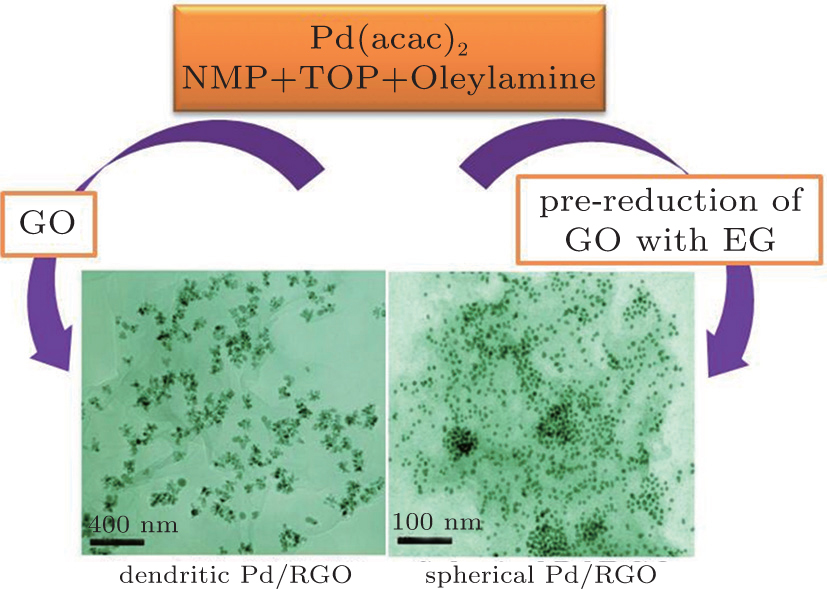 | Fig. 1. Illustration of the synthesis procedure for the DPNs/RGO and SPNs/RGO catalysts. |
Palladium acetylacetonate (Pd(acac)2 99%), trioctylphosphine (TOP, 90%), oleylamine (> 70%), and 1-methyl-2-pyrrolidinone (NMP, ACS reagent grade) were purchased from Sigma Aldrich. Graphite power (SP grade) were purchased from Sinopharm Chemical Reagent Co., Ltd., China. Other chemical reagents were analytical grade and used as received without further purification.
First, our GO was produced by a modified Hummers method[11] and pre-reduction of GO with few oxygen containing surface groups were made by using EG as the reductant.[12] In a typical procedure for preparation of DPNs/RGO, 10 mg GO was dissolved in 20 ml NMP by ultrasonic 2 h. Then, under a protect of nitrogen flow, a proper amount of Pd(acac)2 was added into 0.1 mL TOP, which was then added to 5 mL of oleylamine and injected into the GO solution. The temperature was raised to 60 ° C and kept at this temperature for 10 min. Then the solution was heated up to 200 ° C for 2 h. The resulting solution was cooled to room temperature and then 30 mL ethanol was added to yield a black precipitate which was collected by centrifuging. The resulted black precipitations were dried completely at 50 ° C. The SPNs/RGO composite was prepared by adding pre-reduction of GO to replace GO in the above-mentioned solvothermal system by a similar procedure.
Glassy carbon (GC) electrode, 5 mm in diameter (electrode area 0.2 cm2), polished with 0.05 μ m alumina to a mirror-finish before each experiment, was used as substrates for supported catalysts. For the electrode preparation, typically, 3 mg catalysts were added into 0.5 mL 0.05 wt.% Nafion solution, and then the mixture was treated for 1 h with ultrasonication for uniform dispersion. A measured volume (30 μ L) of this mixture was dropped by a microsyringe onto the top surface of the GC electrode. The as-obtained catalyst modified GC electrode was employed as the working electrode in our experiments.
The Raman spectrum was used to study the integrity and electronic structure of the samples on the Raman system YJ-HR800 with confocal microscopy. X-ray diffraction (XRD) analysis was performed on a Rigaku D/MAX 2400 x-ray diffractometer with Cu KR radiation (λ = 0.15418 nm). The analysis of the composition of the catalyst was obtained with a Thermo IRIS Intrepid II inductively coupled plasma atom emission spectrometry (ICP-AES) system. Transmission electron microscopy (TEM, JEOL JEM-2010) were used to investigate the morphology of samples. The crystalline of Pd was observed by using high-resolution TEM (JEOL JEM-2010).
All electrochemical measurements were carried out with the CHI 660D electrochemical workstation with the use of a three-electrode test cell at a temperature of 25 ± 1 ° C. A conventional three-electrode system was used with a modified GC electrode as the working electrode (5 mm in diameter), a Pt wire as a counter electrode and a Ag/AgCl (saturated KCl) electrode as a reference electrode, respectively. All electrolytes were deaerated by bubbling N2 for 20 min and protected with a nitrogen atmosphere during the entire experimental procedure.
Figure 2 shows the TEM images of DPNs/RGO and SPNs/RGO composite. Figure 2 shows a representative TEM image of the prepared DPNs/RGO sample, which demonstrates that the synthesized particles have a nanodendritic structure with a number of nanobranches. To statistically analyze their sizes, 50 particles in a microscope image are randomly selected. The average circular diameter of the dendritic nanoparticles obtained by measuring the length from a branch edge to another one on the opposite side is 21 ± 3 nm. In order to further reveal the detailed structure of Pd nanodendrites, HRTEM images of typical nanodendrites are shown in Fig. 2(c). The result shows that the prepared particles have a good crystalline structure with clear lattice fringes. The d spacing for adjacent lattice fringes measured from several different points on a single nanoparticle is 2.23 Å (Fig. 2(c)), which corresponds to the mean value of the face-centered cubic (fcc) Pd (111) planes, [16] indicating that most of the exposed facets of the Pd nanodendrites are {111}. Without GO in the solution, a dendritic Pd structure cannot be formed on the surface of RGO. Instead, the synthesis yields spherical Pd NPs with a diameter in the range of about 7– 8 nm (Fig. 2(d)).
 | Fig. 2. TEM and HRTEM images of (a)– (c) DPNs/RGO and (d) SPNs/RGO. The insert is the HRTEM image of a single Pd NP. |
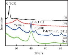
The XRD patterns of graphene oxide (GO), pre-reduction of GO, DPNs/RGO, and SPNs/RGO composites are shown in Fig. 3. There is a characteristic peak of GO at 10.2° , which is consistent with the diffraction peak of GO in the literature.[13] It can be seen that the typical diffraction peak (002) of pre-reduction of GO shifts to a higher angle after reduction by EG. This could be attributed to the fact that GO nanosheets are partially reduced to graphene and restacked into an ordered crystalline structure.[14] It is obvious that the position of the (002) diffraction peak moves slightly to a higher angle after deposition of DPNs on RGO, which indicates that GO is further converted to the crystalline graphene, and the conjugated graphene network (sp2 carbon) has been reestablished due to the NMP reduction process. When DPNs are deposited on the surface of RGO to form DPNs/RGO composites, the four characteristic diffraction peaks correspond to (111), (200), (220), and (311) crystalline planes of Pd. The reflection peaks are consistent with those of an fcc crystalline structure of bulk Pd (JCPDS, Card No. 46-1043). However, SPNs on RGO show only one broader (111) peak. The increased (111) peak width and the disappearance of the other high-angle diffraction peaks confirm that the crystalline domains in the Pd NPs on RGO become much smaller or the changes in the particle’ s size direct using the RGO as the substrates.[15] On the basis of Scherrer’ s equation through line broadening of the Pd (111) peak, the average particle size of Pd NPs for DPNs/RGO and SPNs/RGO were calculated to be 24 and 7.2 nm, respectively, which is consistent with results of the TEM analysis.
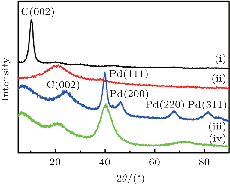 | Fig. 3. XRD patterns of (i) GO, (ii) pre-reduction of GO, (iii) DPNs/RGO, and (iv) SPNs/RGO, indicating that DPNs and SPNs have been deposited on the surface of RGO. |
For comparison, micro-Raman spectroscopy was used to characterize the GO before and after EG reduction (Fig. 4). The typical features in the Raman spectra are the G band at 1593 cm− 1 and the D band at 1352 cm− 1. The G-Band represents the sp2 in plane vibration of carbon atoms, which is the characteristics of most of the carbon related materials. The D-band peak stands for the defective band. This can be due to the vibration of sp3 bonded carbon atoms, impurities and defects present in the material. The intensity ratio (ID/IG) of D band to G band of the GO is about 0.96. As depicted in Fig. 4, with the reduction, the intensity ratio of ID/IG of RGO (1.15) increased significantly. It is known that the ID/IG ratio is inversely proportional to the reciprocal of the average crystallite size in graphite materials. These observations confirm that most oxygen functionalities in the GO are removed and the extent of conversion of GO to RGO can be controlled by alteration of reductant.
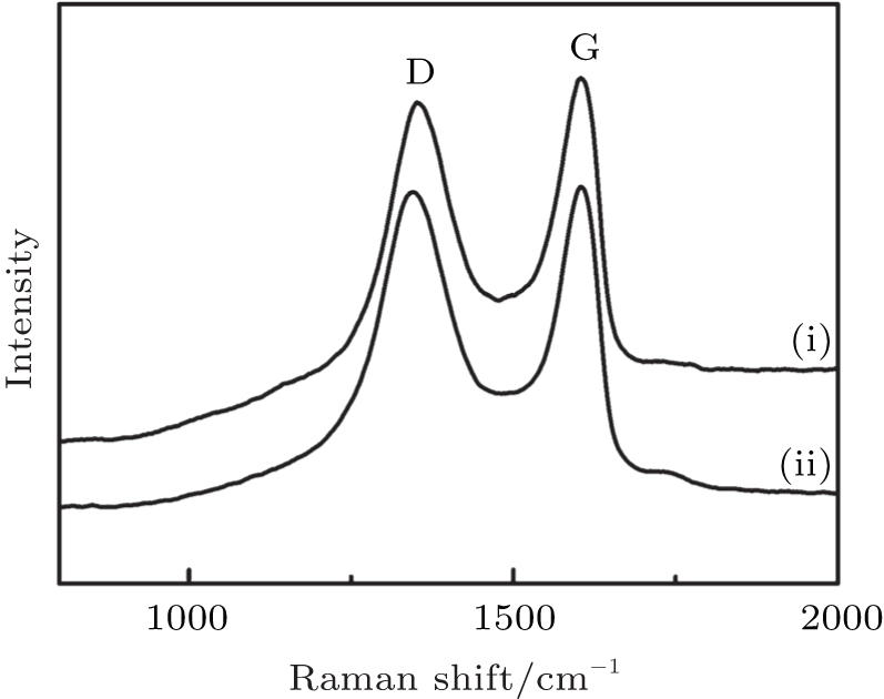 | Fig. 4. Raman spectra of (i) GO and (ii) RGO. |
Although the detailed mechanism for the growth of the dendritic particles remains elusive, the formation of nanodendrites may be the result of the utilizing structure-directing agents in the reaction solution. It has been demonstrated that the shape of the final nanostructures could be finely tuned by using structure-directing agents with different functional groups, for example, acids or amines.[17] In our experiment, GO serves as a structure-directing agent and substrate to direct the growth of the as-prepared DPNs/RGO composites. The GO sheets with hydroxyl, carboxyl, and epoxy groups are introduced on carbon nanosheets due to oxidation procedures. The group in the GO surface possess binding ability to the Pd surface. In a manner similar to that of 2, 3-diketo-l-gulonic acid acting as a shape-directing agent in the synthesis of highly anisotropic Pt nanostructures, [18] the GO is considered to play the shape-directing role and have a profound impact on the crystal growth, resulting in the appearance of dendritic nanostructures as shown in Fig. 3. Without GO in the solution, the synthesis yields spherical Pd NPs formed on the surface of RGO. The group on the GO surface has a profound impact on the Pd nanostructure.
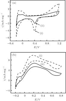
The practical composition of Pd in different samples is evaluated by ICP-AES analysis. The obtained ICP-AES composition for the DPNs/RGO and SPNs/RGO with metal loading of 35.6 and 33.2 wt.%, respectively. The oxidation currents of cyclic voltammograms and chronoamperometry tests are calibrated to the measured metal loading for further comparing the activities of different catalysts. The electrochemical reactivity and electrochemically active surface area of different catalysts are determined by the area of the hydrogen adsorption/desorption peaks in the CV measurements performed in 0.25 M H2SO4 electrolyte at a scan rate of 20 mV· s− 1. Figure 5(a) is the CV curves of DPNs/RGO and SPNs/RGO in the 0.25 M H2SO4 without formic acid. The current density in the hydrogen adsorption/desorption of the DPNs/RGO is larger than that of SPNs/RGO, indicating a larger ECAS for DPNs/RGO, which is believed to be a result of the dendritic structures. It is found that the ECSA value of DPNs/RGO (51.3 m2· g− 1) is higher than the SPNs/RGO catalyst (38.6 m2· g− 1). This result also reveals that the DPNs/RGO are electrochemically more accessible, which is very important for the electrocatalytic reactions. In addition, the double-layer capacitance is also obtained from the cyclic voltammetry data. The increased double-layer thickness of the DPNs/RGO based electrodes reflects the higher specific surface area of the support composite.
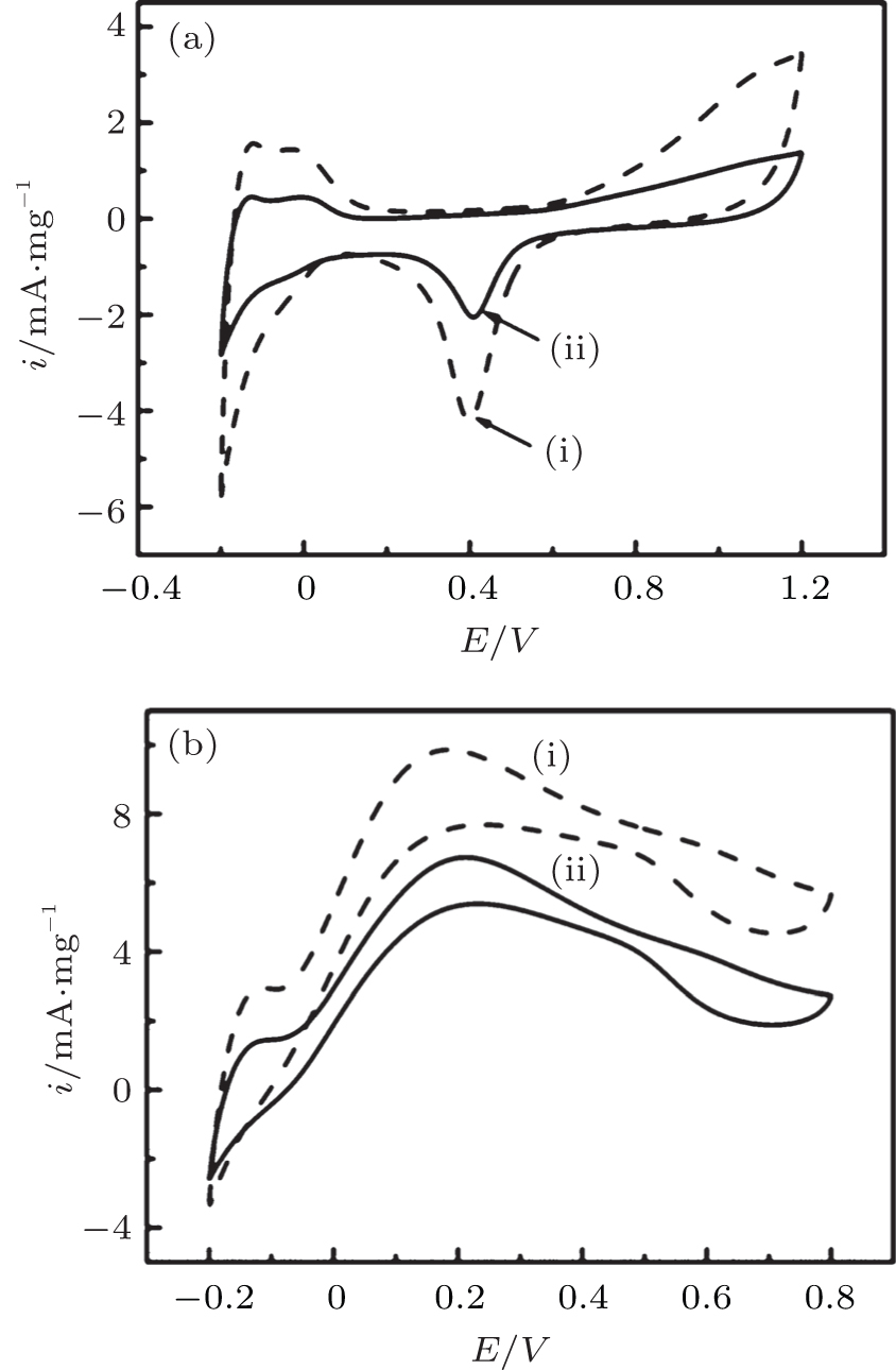 | Fig. 5. (a) Cyclic voltammograms of different catalysts in nitrogen saturated aqueous solution of 0.25 M H2SO4 at a scan rate of 20 mV· s− 1; (b) cyclic voltammograms of formic acid oxidation on the catalysts in 0.25 M H2SO4 + 0.25 M HCOOH solution at a scan rate of 50 mV· s− 1. (i) DPNs/RGO; (ii) SPNs/RGO. |
Figure 5(b) compares the formic acid oxidation activities of the two Pd catalysts in 0.25 M H2SO4 containing 0.25 M HCOOH. As shown in Fig. 5(b), the highest HCOOH oxidation current can be observed in the DPNs/RGO sample, indicating the highest catalytic activity for HCOOH oxidation. The specific mass activities of the DPNs/RGO and SPNs/RGO calculated from the forward-scan currents are 6.74 and 9.86 mA· mg− 1, respectively. The results indicate that the dendritic Pd particles remarkably promote the reaction rate of the formic acid oxidation reaction on the Pd-based catalysts. The significant enhancement for the catalytic activity of HCOOH oxidation on the DPNs/RGO electrode is related to the dendritic Pd structure.
The chronoamperometry (CA) curves for the DPNs/RGO and SPNs/RGO catalysts are shown in Fig. 6. The polarization current for the formic acid oxidation reaction on these two catalysts shows a significant decay initially and reaches a stable value after polarization at 0.1 V. The current decay for the HCOOH oxidation reaction indicates the slow deactivation of Pd-based electrocatalysts by adsorption of CO or CO-like intermediates.[19] However, the stable mass specific current for the formic acid oxidation reaction on DPNs/RGO is 1.96 mA· mg− 1, significantly higher than 0.62 mA· mg− 1 SPNs/RGO. This indicates that DPNs/RGO catalysts also have a much higher stability toward the poisoning by adsorbing CO or CO-like intermediate species during the HCOOH oxidation as compared to SPNs/RGO catalysts.
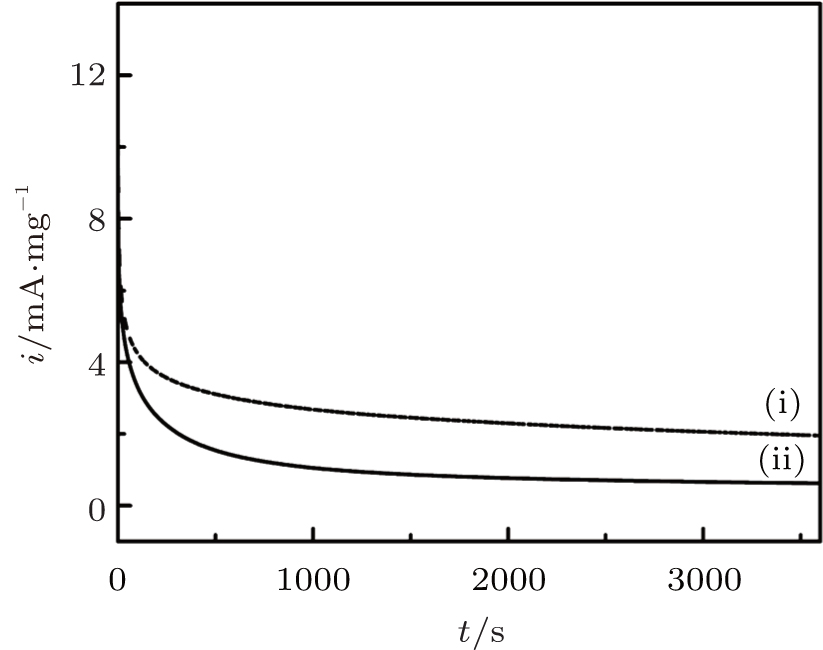 | Fig. 6. Chronoamperometry curves of different catalysts in 0.25 M H2SO4 + 0.25 M HCOOH solution at 0.1 V. (i) DPNs/RGO; (ii) SPNs/RGO. |
Furthermore, Pd nanodendrites have a higher electrocatalytic activity and stability for formic acid oxidation compared to the spherical Pd structure prepared. These enhanced electrocatalytic properties of dendritic particles may be attributed to the presence of a large number of active sites for the adsorption of active oxygen atoms, which can readily oxidize the intermediates on the nanocatalysts.[20, 21] In addition, the effective separation of RGO against agglomeration by Pd nanodendrites can also improve electrochemical properties. The dendritic Pd has a larger surface contact or coverage area with RGO materials as compared to 0-dimensional spherical NPs, leading to a large distance between neighbouring graphene nanosheets. The materials with large surface areas exhibit substantial advantages in terms of mass and charge transport by providing shorter effective lengths for both electronic and ionic transport and a higher electrode/electrolyte contact area.[22] As can be seen from the electrochemical results, a more pronounced electrocatalytic activity can be induced by changing the structure of nanocatalysts, indicating that the structural effect plays a more dominant role in enhancing the catalytic performance.
In summary, two Pd-RGO composites, namely, DPNs-on-sheet and SPNs-on-sheet nanostructures, are prepared in this work by a facile solvothermal method. The morphology of the Pd nanocrystals formed on graphene can be tailored by the degree of reduction of graphene. Most importantly, the present study shows that DPNs/RGO catalyst have a much higher catalytic activity than SPNs/RGO electrocatalyst for formic acid electrooxidation, demonstrating a new and powerful approach for the development of high-performance Pd-based electrocatalysts for fuel cells.
| 1 |
|
| 2 |
|
| 3 |
|
| 4 |
|
| 5 |
|
| 6 |
|
| 7 |
|
| 8 |
|
| 9 |
|
| 10 |
|
| 11 |
|
| 12 |
|
| 13 |
|
| 14 |
|
| 15 |
|
| 16 |
|
| 17 |
|
| 18 |
|
| 19 |
|
| 20 |
|
| 21 |
|
| 22 |
|