†Corresponding author. E-mail: quanj@lingnan.edu.cn
*Project supported by the National Natural Science Foundation of China (Grant No. 11304276), the Natural Science Foundation of Guangdong Province, China (Grant No. 2014A030307035), the Cultivation of Innovative Talents in Colleges and Universities of Guangdong Province, China (Grant No. LYM10098), and the Doctor Subject Foundation of Lingnan Normal University of China (Grant No. ZL1004).
We investigate the dynamic responses of the series parallel-plate mesoscopic capacitors to a time-dependent external voltage. The results indicate that the quantum coherence between two capacitors strongly depends on the frequency of the external voltage and the distance between the two capacitors (c–c distance). The behaviors of the series capacitance incompletely follow the Kirchhoff’s laws; only in the low frequency case or the limit of the c–c distance, the capacitance approaches to the classical series capacitance. In addition, the real part of the frequency-dependent capacitance shows a maximum and a minimum, which appear around the peak of the imaginary part. These phenomena may be associated with the plasmon excitation in the mesoscopic capacitors.
The mesoscopic capacitor has been intensively investigated by many researchers.[1– 5] In comparison with the classical capacitor, the mesoscopic capacitor behaves significantly differently due to the quantum effects, the finite density of states of carriers in the electrodes, and the finite screening length to the electron interaction, etc. Therefore, many quantum corrections to the classical capacitance formula have been investigated.[4, 6– 8] The expression of the mesoscopic capacitance at low frequency has been derived, [5, 9] and the frequency-dependent conductance of the mesoscopic capacitor can be expressed as G(ω ) = − iω C(ω ), [5] where ω is the frequency of the external voltages; C(ω ) can be expanded in frequency, and at the linear order, it is described by an equivalent classical circuit consisting of a static capacitor in series to a charge relaxation resistor. Lots of preceding research reported that the quantum coherence between nano-electronic devices has a remarkable effect on the mesoscopic capacitance.[10– 12] Yu et al. discussed the effect on the quantum capacitance by employing a mesoscopic structure with double-barrier, and a sharp capacitance peak at the resonance frequency was observed.[12] Wang et al.[10] presented a theoretical investigation on the frequency-dependent capacitance of a double-plate mesoscopic capacitor, and the theoretical predictions were consistent with the experimental results given by Gabelli et al.[11] In that experiment, more importantly, it was found that all results violate the Kirchhoff’ s law due to the quantum coherence. In this paper, we further develop the self-consistent electron transport theory for multi-mesoscopic conductors proposed in our previous work, [13] and then study which factor may associate to the quantum coherence between the two mesoscopic capacitors. Three aspects are taken into account: (i) the distance between two capacitors; (ii) the electrons number density, and (iii) the frequency of the external voltages. Our study provides useful insights to help understand the electron transport properties in mesoscopic structures, and also will be helpful in designing nano-electronic devices.
In the presence of time-dependent external voltages with frequency ω , the internal characteristic potential uα (r, ω ) in the α reservoir can be obtained via the Poisson equation[13]
 |
where Π (r, r′ , ω ) is the frequency-dependent Lindhard function, 
The model we considered here consists of three large parallel mesoscopic conductors with large cross-sectional area S, which occupy three regions x < 0, d < x < d + b, and x > 2 d + b. The three conductors can form two parallel-plate mesoscopic capacitors in series, as depicted in Fig. 1, in which the plate– plate (p– p) distance and the capacitor– capacitor (c– c) distance are d and b, respectively. The dashed-line box labeled by Ω includes the whole capacitors and parts of the reservoirs; it is large enough to cover all the regions with varying distributions of potentials and charges.
To proceed, we assume that in all the occupied regions, the electrons are confined by hard-wall boundaries along the y and z directions, and allowed to move along the x direction in regions 1 and 3. In the finite region 2, the electrons are also confined along the x direction. So the wave functions with energy E and wave number kx in regions I (I = 1, 2, 3) read
 |
with

where m = (my, mz) is the compound index and labels the transverse mode number, and 
When a voltage δ V1(ω ) is applied on region 1, if one ignores the fringe field effect and uses the fact that 
 |
with boundary condition

In Eq. (3), the imaginary part of Π (x, x′ , ω ) in regions 1 and 3 is given by
 |
with

where fm = fm(E) is the Fermi– Dirac distribution function, 


 |
with

The imaginary part of 
 |
with

where 

Then, the real parts of 
 |
Hence, the induced charge density in the system reads[13]
 |
The total charge δ Q1(ω ) in the half portion of Ω is given by
 |
Using the definition
 |
and substituting Eq. (9) into Eq. (10), we have
 |
With the Poisson equation
 |
we may then write
 |
In our numerical calculation at zero temperature, the length and the energy are measured in units of the Bohr radius a0 and 

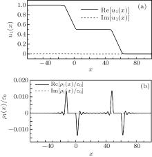
Because the charges accumulated in the mesoscopic structures and the internal potential induced by these charges can give an insight into the electron properties under time-dependent perturbation, and also reveal the meanings of physical quantities in external voltages, we calculate numerically the distributions of internal characteristic potential u1(x) and induced charge density ρ 1(x), the results are shown in Fig. 2, where d = 10, b = 50, ω = 0.01, and n = 0.01. The curve of u1(x) shows that the potential drops mainly appear in the first and the third plates; u1(x) = 1 (0) in the first (third) conductor, and it decreases gradually when it penetrates the first plate, and remains unchanged in the second conductor, where u1(x) = 1/2. The induced charge is considerable only around the first and the third ends of the conductors, and shows some sharp peak structures. In successive detailed discussion, we will find that these peaks may be related with the maximum and minimum of the capacitance. Also, some small oscillations due to the external potential can be observed, and the charge in the intermediate conductor is almost zero. Importantly, u1(x) and ρ 1(x) are both complex with extremely small imaginary parts, but the imaginary part should not be ignored because it gives rise to a real admittance, which actually corresponds to the charge-relaxation resistance.
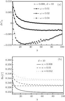
To illustrate the quantum coherence between the mesoscopic capacitors, we discuss the capacitance as a function of the c– c distance for different frequencies of the external voltages (Fig. 3(a), d = 10, n = 0.008) and different electron number densities (Fig. 3(b), d = 10, ω = 0.01). Here, we do not present the imaginary part of the capacitance because it is too small and unchangeable with the variation of the c– c distance.
 | Fig. 3. The Δ CR as a function of the c– c distance b for (a) different frequencies and (b) different electron number densities. |
Figure 3(a) shows that in the low-frequency case, the real part of the capacitance difference Δ CR, where Δ CR = Re[CT − CS/2], decreases to zero with the increase of the c– c distance, but for high frequency, Δ CR is still considerable in large c– c distance. In the classical circuit, as is known, the Kirchhoff’ s law requires that CT should be equal to CS/2, however, the results here indicate that Δ CR depends on the frequency and the c– c distance. These behaviors indicate that in the high-frequency case, the quantum coherence is more obvious than that in the low-frequency case. In addition, one notices that in Eq. (5), the Lindhard function is related to the Fermi wave vector, which is a full description of the carrier density in the system. Different carrier density stands for different material or different carrier-doping density. From the profiles of Fig. 3(b), a drop peak of the capacitance curve can be observed when the c– c distance is small, but with the increase of the c– c distance, the peak decreases rapidly to the closely neighboring horizontal line, which corresponds to CS/2 with different densities. From the results given above all, it can be concluded that the quantum coherence strongly depends on the c– c distance, especially at small c– c distance, and the quantum coherence weakens with the c– c distance increasing, and even disappears in the large c– c distance limit.
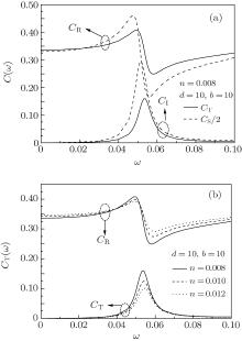
In Fig. 4(a), where n = 0.008, d = 10, and b = 10, the frequency-dependent behaviors of the series capacitance are discussed. It can be seen from the curves of CT (straight line) and CS/2 (dashed line) that the imaginary part CI, where CI = Im[CT] or Im[CS/2], shows a peak structure in the region 0.04 < ω < 0.08. Generally, there is plasmon excitation for interacting electron gas in bulk; it is significant to ask whether there is some quasi-particle excitation related to the collective motion of the electrons in the series capacitor. In our previous work, [14] we have given an indication that the quasi-particle oscillation of electron gas would play a key role in time-dependent electron transport in mesoscopic structure. Around these peaks, the oscillation of the real part CR, where CR = Re[CT] or Re[CS/2], can be observed. When the frequency is small (ω < 0.015), the difference is insignificant between CT and CS, and CI is nearly zero, but the differences between them are formally obvious in the high-frequency region, in which CT is smaller than CS/2. Moreover, the oscillation of CR shows a maximum and a minimum. The oscillation of the charge density would lead to the oscillation of the capacitance. We calculate the distribution of the charge density and find that the oscillation is mainly corresponding to the intensity of the charge density, whereas the screening length of the system just changes a little. The largest and the smallest charge densities give rise to the maximum and the minimum capacitances.
 | Fig. 4. (a) Capacitance as a function of the frequency. (b) Capacitance as a function of the frequency for different electron number densities. |
In Fig. 4(b), we plot CT versus the frequency for different electron number densities n by setting d = 10, b = 10, and ω = 0.01. From the curves of CT, one can find that the variation of CT is the same as that in Fig. 4(a), and CI declines with the increase of the electron number density. This is because the larger the imaginary part, the larger the charge relaxation resistance, the oscillation amplitude of CI progressively decreases with the increase of the electron number density; far from the excitation frequency, the oscillation behavior of the mesoscopic capacitance disappears and no imaginary part can be observed.
We have studied the responses of the series parallel-plate mesoscopic capacitors to a time-dependent external voltage. The results show that the quantum coherence between the mesoscopic capacitors plays a key role in the electrons transport, which strongly depends on the frequency of the external voltage and the c– c distance. Due to the quantum coherence, the behaviors of the series capacitance incompletely follow the Kirchhoff’ s laws; only in the low frequency region or the limit of c– c distance, the capacitance approaches to the classical series capacitance. For the frequency-dependent capacitance, its imaginary part shows a sharp peak structure, around which the real part oscillates with the frequency increasing and shows a maximum and a minimum; these phenomena may be associated with the plasmon excitation in the mesoscopic capacitors.
| 1 |
|
| 2 |
|
| 3 |
|
| 4 |
|
| 5 |
|
| 6 |
|
| 7 |
|
| 8 |
|
| 9 |
|
| 10 |
|
| 11 |
|
| 12 |
|
| 13 |
|
| 14 |
|


