


Transport properties of zigzag graphene nanoribbons adsorbed with single iron atom*
[Yang Yu-E, Xiao Yang , Yan Xiao-Hong, Dai Chang-Jie]
, Yan Xiao-Hong, Dai Chang-Jie]
|
|


†Corresponding author. E-mail: fryxiao@nuaa.edu.cn
*Project supported by the National Natural Science Foundation of China (Grant Nos. 11374162 and 51032002) and the Key Project of the National High Technology Research and Development Program of China (Grant No. 2011AA050526).
We have performed density-functional calculations of the transport properties of the zigzag graphene nanoribbon (ZGNR) adsorbed with a single iron atom. Two adsorption configurations are considered, i.e., iron adsorbed on the edge and on the interior of the nanoribbon. The results show that the transport features of the two configurations are similar. However, the transport properties are modified due to the scattering effects induced by coupling of the ZGNR band states to the localized 3d-orbital state of the iron atom. More importantly, one can find that several dips appear in the transmission curve, which is closely related to the above mentioned coupling. We expect that our results will have potential applications in graphene-based spintronic devices.
Graphene, a single layer of carbon, has attracted much attention of both experimentalists and theoreticians since its synthesis in 2004.[1– 5] It is a zero-gap semiconductor with a linear band energy dispersion around the Fermi level.[6] Due to its striking physical properties, such as a zero-energy anomaly in the quantum Hall effect, [7] very high carrier mobility, [8, 9] and half metallicity, [10] graphene is a promising candidate for applications in nanoelectronic and spintronic devices. In various applications, graphene thin strips of various shapes are often required. These thin strips are known as graphene nanoribbons (GNRs).[11, 12] Two unique GNRs are zigzag graphene nanoribbons (ZGNRs) and armchair graphene nanoribbons (AGNRs), different in the atomic arrangement of the edges. The electronic properties of the GNRs are strongly dependent on their edges as well as on their widths.[13]
Due to the presence of the edges in GNRs, GNRs offer a possibility of achieving tunable electronic properties, such as the edge modification by B, N, − OH, − CH, etc, [14– 19] the application of a transverse electric field, [20] and doping or adsorption of external atoms or molecules.[21– 23] Also, adsorption or doping of external atoms could result in a spin-polarized current in the ZGNRs.[24– 26] Martins et al.[26] showed that the boron-doped graphene nanoribbons have a spin-anisotropic scattering process. Caterina et al.[27] reported that the spin filtering effect is significantly enhanced when the Co adatom is at the edge of the graphene nanoribbons. Rigo et al.[25] revealed a spin-dependent transport property upon Ni adsorption on the graphene nanoribbons.
When graphene nanoribbons are fabricated, iron (Fe) acts as an important catalyst. The graphene layers are likely to have Fe impurities. Therefore, it is necessary to take into account the effect of the Fe impurity on the electronic transport in nanodevices based on graphene nanoribbons. Recently, Longo et al.[23] reported that the Fe impurity can induce a magnetic behavior in GNRs. Gyamfi et al.[28] investigated the electronic properties and the adsorption site of Fe adatoms on monolayer and bilayer graphene by scanning tunneling microscopy. Eelbo et al.[29] observed a nonzero x-ray magnetic circular dichroism (XMCD) signal and proved that the Fe adatom is paramagnetic and exhibits an out-of-plane easy axis, while the branching ratio indicated high-spin ground states. Motivated by those experimental and theoretical findings, in this paper, based on the first-principles calculations, we investigate the effects of a single Fe adatom on the electronic and transport properties of the ZGNRs. The metallic character of the ZGNRs does not change upon the Fe atom adsorption. However, the adsorbed Fe atom introduces additional localized states, modifying the transmission spectrum. In particular, the electronic transmission near the Fermi lever could be lowered down to zero, while two peaks remain. Through the analysis of the projected density of states (PDOS), we illustrate the mechanism of such suppression of transmission. The results show that these localized states act as a scattering quantum dot coupling with the extended states of the quantum channel, which break the spin symmetry of conduction, suggesting the possibility of tuning the spin-polarized transport upon the adsorption of the Fe atom.
The electronic structures and the equilibrium geometries were obtained using the density-functional theory (DFT)[30] with the Perdew– Burke– Ernzerhof (PBE) functional[31] for the generalized gradient approximation (GGA)[32] exchange– correlation potential implemented in the Vienna ab initio simulation package (VASP). The plane wave cutoff energy was set to 450 eV. The convergence criteria for energy and force were 10− 4 eV and 0.02 eV/Å , respectively. Vacuum spacing of at least 15 Å was placed between adjacent ZGNRs to prevent the interactions.
The transport properties were calculated by means of the nonequilibrium Green' s function (NEGF)[33– 35] combined with the generalized gradient approximation in the DFT. All transport calculations were performed by an ab initio DFT code, open source package for material explorer (OpenMX).[36] The pseudoatomic orbitals (PAOs) located at the atoms were used as the basis functions. The PAOs basis functions are specified as H5.0-s2, C5.0-s2p1, and Fe8.0s-s2p2d2. The abbreviation is used as follows. Take Fe8.0s-s2p2d2 as an example, Fe is the atomic symbol, 8.0 indicates the cutoff radius (Bohr), and s2p2d2 means that two primitive orbitals for s, p, and d orbitals are employed. A cutoff energy of 250 Ry was used in the numerical integrations and in solving the Poisson equation.
Following the previous convention, [13– 16] the GNRs with zigzag edges on both sides are classified by the number of the zigzag chains (Nz) across the ribbon width, see Fig. 1.
 | Fig. 1. The structures of 8-ZGNR for (a) electronic and (b) transport property calculations. The numbers 1– 3 indicate the adsorption positions investigated in the present work. The grey and white spheres represent C and H atoms, respectively. |
We refer to a GNR with Nz zigzag chains as Nz-ZGNR, Nz-ZGNR can be divided into two groups with respect to their symmetries, i.e., odd (asymmetric) and even (symmetric) ZGNRs. Figure 1(a) shows the case of a ZGNR with eight zigzag chains (8-ZGNR) in a supercell of five repeated units, and the edges are passivated with the hydrogen atoms. The position of the Fe adatom is placed from the center toward the edge, which are labeled as 1– 3 in Fig. 1. For Fe on graphene, the adsorption site is the hollow site.[25] After relaxation, in the 1 and 2 configurations, the Fe adatom is 6-fold coordinated on the hollow site with the heights above the GNR plane of 1.54 Å and 1.71 Å , respectively. In configuration 3, the Fe adatom is 3-fold coordinated with an Fe-GNR plane distance of 1.82 Å .
In order to explore the structural stability, we calculate the adsorption energy as

where E[Fe/ZGNR] and E[ZGNR] are the total energies of the Fe-adsorbed and the pristine ZGNRs, respectively, and E[Fe] is the total energy of an isolated Fe atom. The results are presented in Table 1, which reveals that the 2 site is the most stable one amongst all three sites. Site 2 is at the edge of the ZGNR. This means that the Fe atom adsorbing on ZGNR tends to sit at the edge of the ribbons. A similar behavior was also exhibited in the case of the Co-adsorbed graphene nanoribbons.[27]
| Table 1. Adsorption energy of the Fe-adsorbed configurations depicted in Fig. 1. |
The electronic structures of Fe-adsorbed 8-ZGNR with the Fe atom at three unequivalent adsorbing sites (1, 2, and 3 in Fig. 1(a)) are investigated. The supercell used in the present calculation has five prime cells of 8-ZGNR including a Fe atom, which is shown in Fig. 1(a). The energy band structures of pristine 8-ZGNR and Fe-adsorbed 8-ZGNR are shown in Fig. 2. We consider the pristine 8-ZGNR with ferromagnetic (FM) coupling of the edges. Due to the effect of the ribbon edges, π and π * electronic states give rise to flat energy bands near the Fermi level for the pristine 8-ZGNR (Fig. 2(a)). Meanwhile, 8-ZGNR at FM coupling defines a metallic behavior, which is in agreement with the previous results.[26] Rigo et al.[25] reported that the electronic character of the GNR is not altered by the adsorption of a single Ni atom, although its presence does perturb the energy bands. In this study, we find that the same holds when a single Fe atom is adsorbed at different sites. Figures 2(b)– 2(d) show that the spin-up and spin-down bands crossing point at the Fermi level is maintained for 8-ZGNR with the Fe atom at various adsorption sites. Fe d electrons are localized states, as shown in the flat bands induced by the Fe atom in Fig. 2. However, the spin-down energy bands are more perturbed than the spin-up energy bands by the presence of the Fe adatom. When the Fe atom is located at site 1, the spin up states near the Fermi level are similar to the pristine ones as shown in Fig. 2(b). It means that the Fe atom in the middle of 8-ZGNR only has a weak effect on the edge states, and the hybridization between the Fe d electrons and the C p electrons around the Fe atoms is also weak. That is why site 1 is the most unstable site as shown in the adsorption energy in Table 1. When the Fe atom is near the edge of 8-ZGNR, the coupling becomes strong, as shown in Figs. 2(c) and 2(d). Especially at site 3, there are nearly no straight bands, as shown in Fig. 2(d), and no similarity to the pristine bands. So sites 2 and 3 have larger adsorption energies.
 | Fig. 2. Energy band structures of (a) pristine 8-ZGNR and (b)– (d) Fe-adsorbed 8-ZGNR with Fe at adsorption sites 1, 2, and 3. Spin up (down) states correspond to black (dot) lines. |
After computing the electronic properties of single Fe atom adsorbed on 8-ZGNR, we next investigate their transport properties. Our modeling setup is depicted in Fig. 1(b). The system is divided into three parts: two electrodes and a scattering region. The electrodes are taken as two semi-infinite metallic GNRs, and the scattering region is described by five unit cells of 8-ZGNR plus three unit cells coupling regions on each side. The transmission spectra of the pristine 8-ZGNR are shown in Fig. 3(a). It displays a transmission with a well-known steplike character, where the height of each step corresponds to the number of states available for transport at that energy. There are two peaks residing discretely on both sides of the Fermi level for the spin down and the spin up transmission channels, respectively, which are contributed by the corresponding density of states (DOS) peaks near the Fermi level as shown in Fig. 3(b). To study the peaks in detail, we further calculate the projected density of states (PDOS). We observe that the states near the Fermi level are arisen from the edge carbon atoms of the graphene nanoribbons (Fig. 3(c)), which is consistent with other calculations.[37]
 | Fig. 3. Spin-polarized transmission spectra of (a) pristine, (d) 1, (e) 2, and (f) 3 configurations. (b) The total DOS of pristine 8-ZGNR and (c) the PDOS of carbon atoms in edges. The dark lines are for the spin up states and the dot lines refer to the spin down states. |
Upon a single Fe atom adsorption in the 1, 2, and 3 configurations, the transmission spectra change from the pristine quantum step behavior. A number of drops in the whole energy range of the conductance curve are observed as shown in Figs. 3(d)– 3(f). The spin polarized transmissions for the spin-up and spin-down channels are lifted in degeneracy, combining with energy splitting of the two spin channels for the 1, 2, and 3 configurations. These results can be attributed to the interaction between the impurity-induced localized states and the propagating states composed by C 2p π /π * orbitals in the graphene nanoribbons, [37– 40] which can be understood by the DOS shown in Fig. 4. Figures 4(a)– 4(c) are the total DOS (TDOS) for the 1, 2, and 3 configurations, respectively. To study the contribution of the Fe impurity and the edge states for the transmission spectra, we further calculate the projected density of states. Figures 4(d)– 4(f) show the PDOS of the 3d orbital of the single Fe atom for the 1, 2, and 3 configurations. Figures 4(g)– 4(l) show the projected densities of states for the carbon atoms at the edge (C in Fe edge) and the opposite edge (C in opposite edge).
 | Fig. 4. Total DOS for (a) 1, (b) 2, and (c) 3 configurations; PDOS of the 3d orbital for Fe in (d) 1, (e) 2, and (f) 3 sites; carbon atoms at the edge where Fe is adsorbed (C in Fe edge) for Fe in (g) 1, (h) 2, and (i) 3 sites; carbon atoms at the opposite edge (C in opposite edge) for Fe in (j) 1, (k) 2, and (l) 3 sites. |
As one finds from Figs. 3(d)– 3(f), the adsorption of the Fe atom induces a suppression of the electronic transmission around the Fermi level for both spins and for all adsorption configurations. Also, the spin-down transmission is suppressed significantly. These suppressions can be explained by the scattering effects induced by coupling of the ZGNR band states to the localized 3d orbital of the Fe atom. In graphene, the carbon atoms are all in a plane with sp2 hybridization. The binding of the Fe adatom with a carbon atom would change the bonding type of carbon from sp2 to sp3, therefore affecting the electronic wavefunctions near the adatom. In other words, such binding produces localized states in the vicinity of the adatom and affects the π bonding and the conductance of the nanoribbon. To further study the effect of the localized states on the conductance, we select the 2 configuration (the most stable one) as an example to compare the PDOS (Fig. 4(e)) and the transmission spectrum (Fig. 3(e)). One can see that there is a strong correlation between the localized 3d orbital energies and the conductance dips. In the transmission spectrum, there is a resonance located at about − 0.27 eV for the spin-up states, which is related to the 3dxz orbital. For the spin-down states, two separated channels close at about − 0.35 eV and − 1 eV below the Fermi energy due to the located 3dxy and 3dx2− y2 orbitals, respectively. Due to the coupling with the carbon atoms, these energies also appear in the PDOS for the C atoms at the Fe edge (Fig. 4(h)). Moreover, the peak in the transmission corresponding to the highest (lowest) spin-up (down) occupied (unoccupied) state decreases compared to the corresponding state in the pristine system. Similar results are also observed for the 1 and 3 configurations.
Furthermore, the conductance drop clearly depends on the position of the adatom, which can be seen from Figs. 3(d)– 3(f). When the Fe atom is in the interior of the ribbon, i.e., far away from the edge, there are two drops near the Fermi energy for both spins. One also can see an obvious dip of the spin-down conductance, i.e., a complete blocking of the electron transmission. By moving the adatom from the center toward the edge, there are more and more dips appearing in the conductance curve. As mentioned above, for the 8-ZGNR, it is the edge states that dominate the electronic transport. If the localized adatom resides at the edge of the nanoribbon, the effect of the adatom on the whole electronic wavefunction will be maximum. When the Fe adatom is in the interior of the nanoribbon, the effect of the localized adatom states on the edge will decrease due to the increase of the distance between the adatom and the edge of the ribbon.
Another important point is that the spin symmetry in the transmission spectrum of the 8-ZGNR is broken by the adsorption of the Fe atom. To show more clearly, we plot the energy-dependent relative spin polarization of the transmission probabilities, (Tup − Tdown)/(Tup + Tdown), in Fig. 5. High polarizations occur in an energy window around the Fermi level. The spin polarization ratio is up to 100% at about − 0.1 eV in Fig. 5(b), i.e., there is a complete block of the spin down states. The reason is that the spin up states of 3d orbits on the Fe adatom are filled and the partially filled spin down states are located around the Fermi level. The interference mainly takes place between the spin down 3d states of the adatom and the directly transmitted carbon states, i.e., the Fano effect. So, the spin down transmission is significantly suppressed around the Fermi level. As is known, a high polarization is quite essential for the development of the spintronic devices.
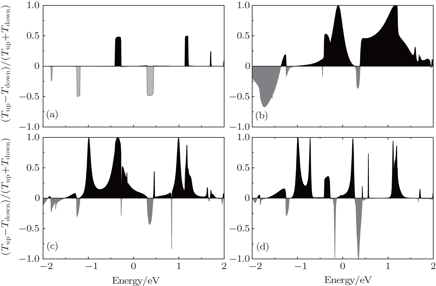 | Fig. 5. Spin polarization in the transmission spectra for (a) pristine, (b) 1, (c) 2, and (d) 3 configurations. Black and gray represent positive and negative values, respectively. |
Now, we check the effect of the ZGNR width on the transport properties. The positions of the Fe adatom we considered are central and edge positions in the ZGNR. In general, the transport behaviors of ZGNR arise from the characteristics of their electronic structure. Since asymmetric and symmetric ZGNRs exhibit very similar band structures, [41] the transport characteristics of the Fe adsorbed 7-ZGNR (shown in Fig. 6) are similar to those of 8-ZGNR (shown in Figs. 3(d) and 3(f)), so the above analysis can also apply to the 7-ZGNR case. However, when the adatom is in the middle of the ribbon, the spin polarization at the Fermi level is smaller when the width of the ribbon is larger. The spin polarization is 80% for 7-ZGNR, while it is 60% for 8-ZGNR. Therefore, the effect of the adatom in the middle of the ribbon will decrease with increasing width of the ribbon.
 | Fig. 6. Spin-polarized transmission spectra for (a) central and (b) edge of 7-ZGNR. The dark lines are for the spin up states and the dot lines refer to the spin down states. |
We have investigated the structural stability, electronic and transport properties of the zigzag graphene nanoribbons with the adsorption of an Fe atom. It is found that the Fe atom tends to adsorb at the edge of the ZGNR, and the electronic character of the ZGNR is unaltered by the adsorption of the Fe atom. Binding of the Fe adatom with the carbon atom results in extra peaks in the DOS near the Fermi energy of the ZGNR, which produces the localized states and results in the decrease of the conductance. The drop of the conductance is very sensitive to the position of the Fe adatom. When the Fe adatom is in the middle of the ZGNR, its effect on the conductance is minimum. By moving the Fe adatom from the middle of the ZGNR toward the edge, the decrease of the conductance is more obvious. We find that there is a significant difference between the transmission curves for the spin-up and the spin-down channels. The presence of the Fe atom causes closing of the conduction channels at certain energies. High polarizations are obtained near the Fermi level, which suggests a potential application in spintronic devices.
| 1 |
|
| 2 |
|
| 3 |
|
| 4 |
|
| 5 |
|
| 6 |
|
| 7 |
|
| 8 |
|
| 9 |
|
| 10 |
|
| 11 |
|
| 12 |
|
| 13 |
|
| 14 |
|
| 15 |
|
| 16 |
|
| 17 |
|
| 18 |
|
| 19 |
|
| 20 |
|
| 21 |
|
| 22 |
|
| 23 |
|
| 24 |
|
| 25 |
|
| 26 |
|
| 27 |
|
| 28 |
|
| 29 |
|
| 30 |
|
| 31 |
|
| 32 |
|
| 33 |
|
| 34 |
|
| 35 |
|
| 36 |
|
| 37 |
|
| 38 |
|
| 39 |
|
| 40 |
|
| 41 |
|