Au nanorods-incorporated plasmonic-enhanced inverted organic solar cells

Au nanorods-incorporated plasmonic-enhanced inverted organic solar cells |
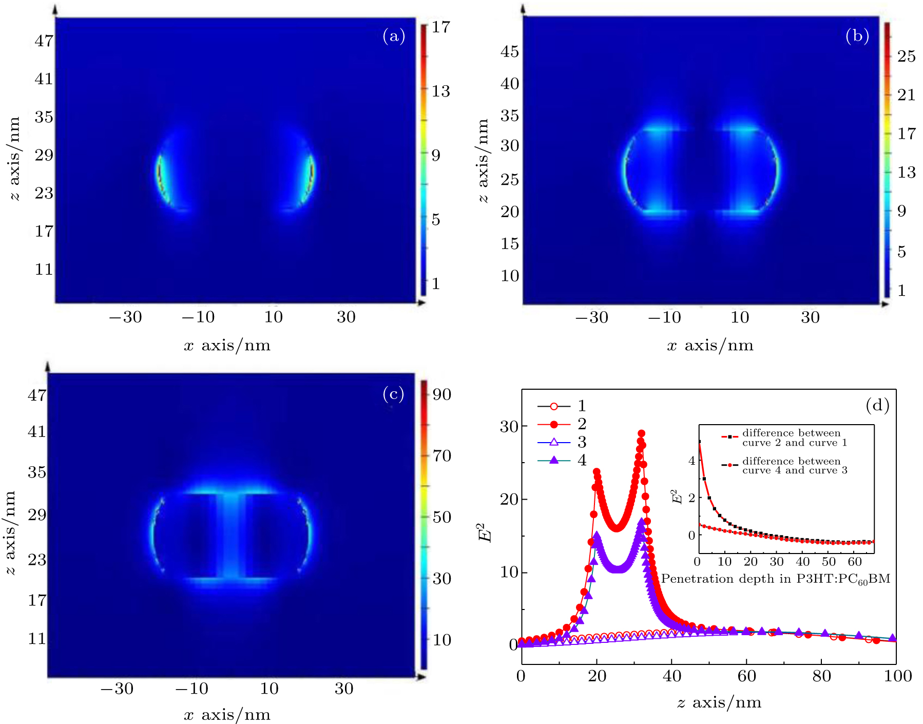
| Simulated electric field distributions around Au NR in the plasmonic device with 8-nm ZnO overlayer at (a) 550 nm, (b) 600 nm, and (c) 635 nm along the XZ plane. (d) Variances of the electric field intensity at 635 nm along the Z axis at x = 0 in the devices (1: ZnO (28 nm)/P3HT:PC60BM; 2: ZnO (20 nm)/Au NRs/ ZnO (8 nm)/P3HT:PC60BM; 3: ZnO (40 nm)/P3HT:PC60BM; 4: ZnO (20 nm)/Au NRs/ZnO (20 nm)/P3HT:PC60BM). The X and Z axes are along the longitudinal axis of Au NR and the incident direction of sun light, respectively. The inset shows the difference in electric field of P3HT:PC60BM layer between the plasmonic and its control devices. |
 |