


Surface morphology and electrochemical characterization of electrodeposited Ni–Mo nanocomposites as cathodes for hydrogen evolution
[Guettaf Temam Elhachmi, Ben Temam Hachemi, Benramache Said† ]
]
]
|
|


†Corresponding author. E-mail: saidbenramache07@gmail.com
In this work, we study the influences of current density on surface morphology and electrochemical characterization of electrodeposited Ni–Mo. The Ni–Mo composite coatings are deposited on pretreated copper substrates by electrolytic deposition. The Ni–Mo solution is taken from nickel sulfate fluid and ammonium heptamolybdate with 10 g/l. The Ni–Mo composite coatings are deposited at a temperature of 303 K with an applied current density of jdep = 10 A/dm2–30 A/dm2. We find that the corrosion resistance is improved by incorporating Mo particles into Ni matrix in 0.6-M NaCl solution. From the potentiodynamic polarization curve of electrodeposited Ni–Mo it is confirmed that the corrosion resistance decreases with increasing applied current density. The x-ray diffraction (XRD) analyses of Ni–Mo coatings indicate three phases of MoNi4, Mo1.24Ni0.76, and Ni3Mo phases crystallites of nickel and molybdenum. The scanning electronic microscopy (SEM) tests indicate that Ni–Mo coatings present cracks and pores.
Broad applications of nickel and nickel-based composite coatings in electrochemistry result from special properties of nickel such as good corrosive resistance in aggressive environments and high catalytic activity in many electrochemical Processes.[1] Thus alloys based on nickel are extensively used in industries due to their significant resistance to wear and corrosion.[2, 3] Various Ni-based composite coatings have been developed by electrolytic deposition technique to improve their physical and mechanical properties.[4] It is a fact that Ni-based binary composite coatings like Ni– Mo, [1, 5] Ni– Al2O3, [6] Ni– SiC, [7] Ni– W, [8] Ni– Cu, [9] and Ni– Sn, [10] were tried to serve as hydrogen electrodes.[11] Molybdenum as a component of composite alloy seems to be particularly interesting on account of its electrochemical properties.[12] Mo cannot be precipitated from aqueous solutions; however, accompanied by iron group metals (Fe, Co, Ni), Mo can precipitate during the electrolysis process under the co-deposition mechanism.[13]
Electrodeposited Ni– Mo alloys are interesting materials according to their high corrosion resistance and low overpotential for the hydrogen evolution reaction (HER).[14] Coatings with 20-wt% Mo possess excellent protective properties. Therefore, 20-wt% value is considered as the optimum concentration.[13] They are known for premium hardness, wear, and corrosion (especially in the corrosive media containing Cl– ions) resistance.[15] Many investigations have been devoted to the deposition of these alloys.[14] Ni– Mo was found to be the best and stablest electrode with overpotential of 0.18 V in 6-M KOH solutions.[11] About properties of hardness and HER, 15-wt% and 23-wt% Mo are considered to be the optimal concentrations respectively.[13, 16] The co-deposition mechanism for such alloys is not completely understood. Several hypotheses have been proposed and many investigations describe the possible multi-step reduction of some Mo species. Zeng et al.[17] and Chassing et al.[18] showed that in NiSO4 solution, molybdate was only reduced to a mixture of polyvalent Mo oxides and/or hydroxide.[14]
In this paper, we study the effect of plating deposition current density on the Ni– Mo electrodeposited coatings.
In our experiment, Ni– Mo coatings were electrodeposited on copper substrates from an electrolytes containing nickel sulfate (NiSO4· 7H2O), ammonium heptamolybdate ((NH4)6Mo7O24· 4H2O), sodium chlorure (NaCl), ammonium chloride (NH4Cl), and boric acide (H3BO3), (see Table 1). Bid stilled water was used for electrolyte preparation. The pH of the solution was adjusted by addition of the aqueous HCl or NaOH solution. Copper substrates (99.9%) with dimensions of 20 mm × 10 mm × 0.19 mm were used as cathode. However, the anode was a nickel sheet (20 mm × 10 mm × 2 mm) of commercial purity (99.99 %). Prior to deposition, the substrates were degreased by using a solution containing 50-g/l Na2CO3 + 15-g/l NaOH to remove oil and greases then pickled in 10% HCl solution to remove oxide traces.
In addition, Ni– Mo coatings were deposited at different plating current densities namely; 10, 15, 20, 25, and 30 A/dm2. The electrodeposition was carried out at (30 ± 1) ° C, pH of 5.5– 6.0 during 90 min. The bath was stirred by a magnetic stirrer at the same stirring speed.
| Table 1. Chemical compositions and working conditions of Ni– Mo electrolyte. |
To evaluate the adherence of Ni– Mo composite coatings, the coated samples were heated at 250 ° C for 30 min, which were subsequently quenched in water at ambient temperature.[7]
The morphology and the microstructure of the coatings were investigated using a JSM-6390 Lv scanning electron microscopy (SEM). The compositions of Ni– Mo coatings were determined with energy dispersive x-ray spectroscopy (EDS) analysis tool attached to SEM. Structural investigations and phase composition of the coatings were analyzed by XRD method using a Bruker diffractometer (D8 Advance model) with Cu Kα − radiation (1.5406 Å ). The mean crystal sizes were determined from the peak width using Scherrer’ s equation modified by Warren and Biscoe:[14]
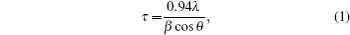
where θ is the position of the peak in the diffractogram, β is the integral peak broadening (in radians) which is approximately the full width at half maximum (FWHM) value, λ is the wavelength (in Å ), and τ is the grain size. For estimating the crystal size, an average value is considered to be FWHM (or β ).[14]
In order to confirm our investigation, the corrosion tests were carried out by using both the lost weight method of Ni– Mo alloy specimen and potentiodynamic polarization method.
2.4.1.Lost weight method
The corrosion behavior of electrodeposited coating was studied by measuring the lost weight of Ni– Mo alloy specimen immersed in 0.6-M NaCl solution for 15 days. The immersed area is 1.16 cm2.
2.4.2.Potentiodynamic polarization method
Potentiodynamic polarization measurements were conducted by using a standard three-electrode cell with the coated sample (1.16 cm2) as a working electrode, Pt as auxiliary electrode and saturated calomel electrode as a reference electrode, all these electrodes were immersed in 0.6-M NaCl electrolyte. This cell was connected to Voltalab 20 (PGP201) device working at a scanning rate of 0.5 mV/s and in a potential range from − 700 to − 100 mV. Corrosion rate (mm/y), corrosion potential Ecorr (mV), and Tafel slopes (mV/s) were calculated by using Tafel extrapolation technique provided by Volta Master 4 software.[11]
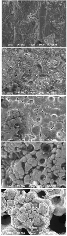
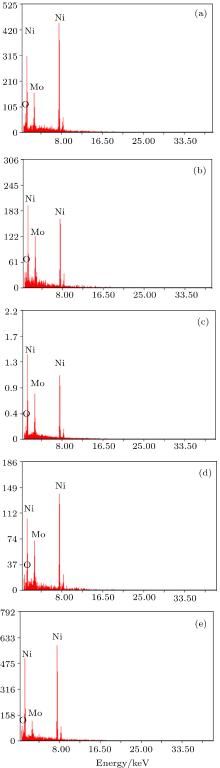
Thermal shock tests show that electrodeposited composite coatings each have an excellent adherence to their substrates. The surface morphologies of electrodeposited Ni– Mo at different plating current densities are shown in Fig. 1. The presence of Mo that is co-deposited with nickel matrix distinctly enlarges the real surfaces of the layers. The whole area of composite coatings observed at highest current density is rough and reveals deep narrow pores (see Figs. 1(d) and 1(e), Figures 1(a)– 1(c) each show a fissured area of Ni– Mo deposit coatings. This fissure area may be attributed to the internal stresses caused by the hydrogen reaction intensification.[19] Chemical compositions of Mo– Ni alloy depend on the applied current density, are shown in Figs. 2(a)– 2(e).
 | Fig. 1. SEM morphologies of Ni– Mo alloy deposits at plating current densities: (a) 10 A/dm2, (b) 15 A/dm2, (c) 20 A/dm2, (d) 25 A/dm2, (e) 30 A/dm2. |
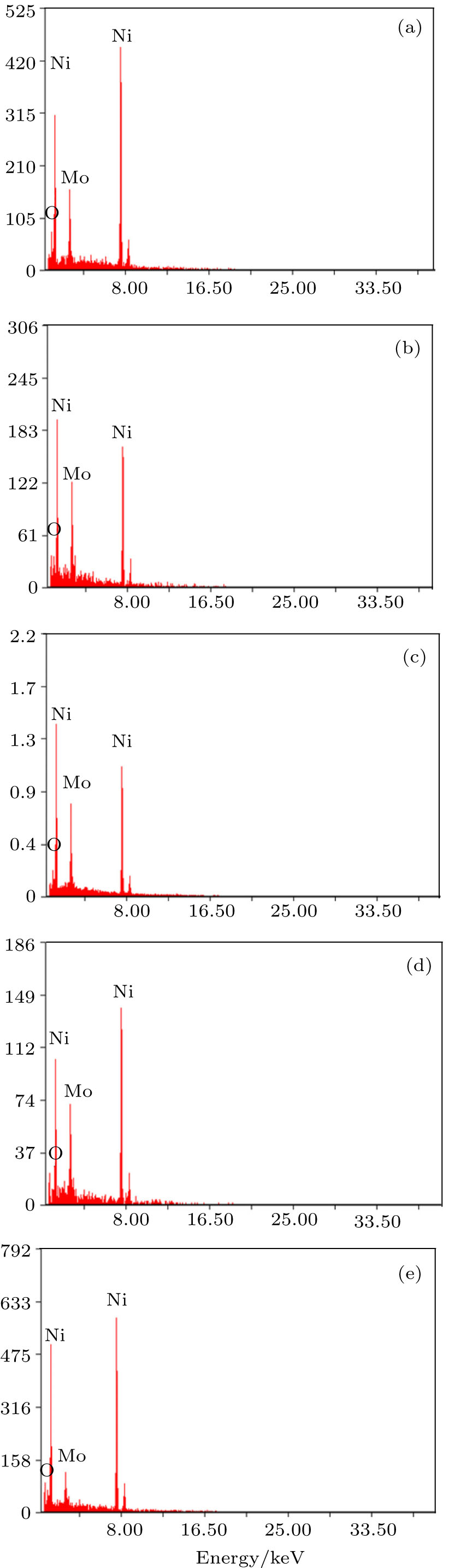 | Fig. 2. EDX analysis of Ni– Mo alloy deposits. |
Figure 3 shows the variation of Mo content with plating current density in the deposit. The Mo content in the deposit varies with the increase of applied current density. With the current density increasing from 10 A/dm2 to 20 A/dm2 the Mo content in the deposit increases from 12.83 wt% to 20.06 wt% (see Table 2). This behavior is due to the rise in the movement of the Mo particle towards the cathode as a result of variation of current density. The current density increasing up to more than 20 A/dm2 causes a drop of Mo content in the deposit, which may be attributed to a partial restraint of Mo particle by nickel ions.
 | Fig. 3. Influence of the applied current density on the composition of Mo in Mo– Ni alloys. |
| Table 2. Corrosion properties of electrodeposited Ni– Mo composites at different plating current densities. |
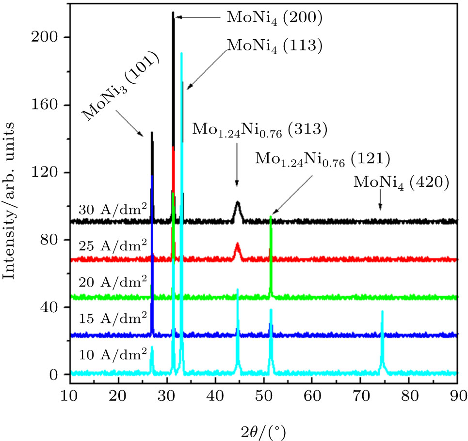
The x-ray analyses of our coatings are shown in Fig. 4. The XRD patterns of the electrodeposited Ni– Mo at different current densities show that the intensity of the peak relating to MoNi4 phase with (200) plane is the highest one. For the current density of 10 A/dm2, the peak of the (200) plane is the highest intensity compared with the others, so that the applied current density enhances the structural property. Also, Ni3Mo phase with (101) plane shows an important intensity of Ni– Mo composite sample deposited at 15 A/dm2, Mo1.24Ni0.76 peaks
 | Fig. 4. XRD patterns of Ni– Mo alloys deposits as a function of applied current density. |
were revealed with planes of (313) and (121) at current densities of jdep = 10 A/dm2 and 20 A/dm2 respectively. But as can be seen from Fig. 4, there appears neither pure Ni peak nor Mo peak, which should be explained as follows: under a high applied current density strong bounds of MoNi4, Ni3Mo, Mo1.24Ni0.76 phases are formed.
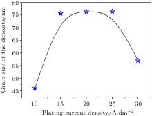
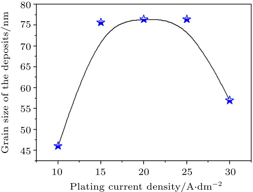
The variation of the grain size of Mo– Ni alloy deposit with current density is shown in Fig. 5. The increasing in electroplating current densities causes a rise in the grain size of deposits due to the increase of molybdenum composition in the alloy as shown in Fig. 3. A decrease of the grain size in the deposit is achieved by an increase of the current density to more than jdep = 25 A/dm2. This behavior may be attributed to molybdenum ions covered by nickel metallic ions, which leads to the conclusion that at high current density the electrolytic process favors the incorporation of grains of low sizes.
 | Fig. 5. Influence of the applied current density on the grain size of the deposit. |
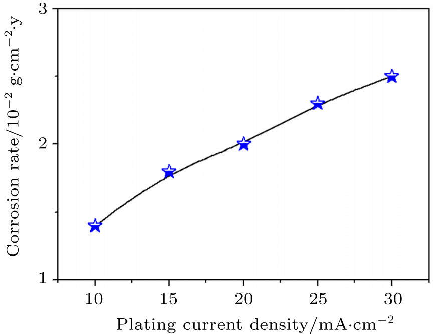
The corrosion tests are carried out by using the lost weight method. Figure 6 shows the variation of corrosion rate with applied current density in an aggressive environment (NaCl 0.6 M) for 15 days at an ambient temperature. As can be seen, the corrosion rate increases with increasing the electroplating current densities due to the fissured and porous surface of composite sample. The reduction of the current density improves the corrosion resistance.
 | Fig. 6. Variation of corrosion rate with electroplating current density. |
The potentiodynamic polarization method is used to evaluate our corrosion test on Cu coated Ni– Mo composite coatings in aggressive (NaCl 0.6 M) environments at an ambient temperature (see Fig. 7). The corrosion potential is measured as a function of time (Ecorr = f(t)), the polarization measurements are given in Table 2. It is clearly seen that a nobler Ni– Mo composite sample containing 12.83 wt% has a corrosion rate of 1.086 mm/y and the least negative corrosion potential Ecorr = − 281.9 mV., This is due to the uniform and low cracked surface, which is in accordance with the lowest grain size obtained at 10 A/dm2. The highest negative value of corrosion potential (Ecorr = − 674.4 mV) and the maximum corrosion rate (357.8 mm/y) are obtained for Ni– Mo composite sample containing ∼ 7.09 wt%. Morphological study of this sample reveals roughness and deep narrow pores, which is due to the bombardment by ion of Cl– aggressive element.
 | Fig. 7. Polarization curves of Ni– Mo deposited composites at different current densities. |
In this work, the effects of applied current density on surface morphology and electrochemical characteristic of electrodeposited Ni– Mo are investigated. The experimental data show that Mo particles can be co-deposited with Ni matrix from nickel sulphate bath. Thermal shock test reveals that Ni– Mo coating deposited presents a good adherence to copper substrate. The surface morphology of each of all coatings shows the fissure and porous surfaces which are dependent on the applied current density. The chemical composition and the grain size of the Ni– Mo alloy vary nonlinearly, showing that the optimal values were achieved at low applied current density. The XRD results indicate a good crystalline structure with (200) preferred growth orientation. Electrochemical tests show that 10 A/dm2 is an optimal value of applied current density in the sense of the lowest corrosion rate and the least value of Ecorr which are confirmed by the lost weight method. From the experiment results of electrodeposited Ni– Mo, we conclude that the Ni– Mo coating should be used as cathode for hydrogen evolution.
The x-ray diffraction data in this work were acquired with an instrument supported by the University of Biskra. We thank Mr. B. Gasmi (Biskra University) for help with XRD data acquisition.
| 1 |
|
| 2 |
|
| 3 |
|
| 4 |
|
| 5 |
|
| 6 |
|
| 7 |
|
| 8 |
|
| 9 |
|
| 10 |
|
| 11 |
|
| 12 |
|
| 13 |
|
| 14 |
|
| 15 |
|
| 16 |
|
| 17 |
|
| 18 |
|
| 19 |
|