
Influences of surface and flexoelectric polarization on the effective anchoring energy in nematic liquid crystal
[Guan Rong-Hua†a)  , Ye Wen-Jiang‡
b) , Xing Hong-Yub) ]
, Ye Wen-Jiang‡, Xing Hong-Yu|
|


†E-mail: ronghua_guan@163.com
‡Corresponding author. E-mail: wenjiang_ye@hebut.edu.cn
*Project supported by the National Natural Science Foundation of China (Grant Nos. 11274088, 11374087, and11304074), the Natural Science Foundation of Hebei Province, China (Grant No. A2014202123), the Research Project of Hebei Provincial Education Department, China (Grant No. QN2014130), and the Key Subject Construction Project of Hebei Provincial University, China.
The physical effects on surface and flexoelectric polarization in a weak anchoring nematic liquid crystal cell are investigated systematically. We derive the analytic expressions of two effective anchoring energies for lower and upper substrates respectively as well as their effective anchoring strengths and corresponding tilt angles of effective easy direction. All of these quantities are relevant to the magnitudes of both two polarizations and the applied voltage U. Based on these expressions, the variations of effective anchoring strength and the tilt angle with the applied voltage are calculated for the fixed values of two polarizations. For an original weak anchoring hybrid aligned nematic cell, it may be equivalent to a planar cell for a small value of U and has a threshold voltage. The variation of reduced threshold voltage with reduced surface polarization strength is also calculated. The role of surface polarization is important without the adsorptive ions considered.
The anchoring phenomenon between liquid crystal (LC) and solid is usually described by the anchoring energy, [1] which can be seen as an anisotropic part of the interface energy. The expression of anchoring energy and its physical effects in the LC cell have been an important content of the LC surface physics.[2]
Physical reasons for the anchoring phenomenon and its microscopic mechanism are important subjects.[3] Recently, Yang et al.[4] have proposed that interface energy should be seen as the total sum of potentials between molecules of LC and the substrate surface. They gave out an expression of the anchoring energy, which turns into an RP formula in the one-dimensional (1D) case. However, the anchoring energy may originate from other physical reasons, such as adsorptive ions, surface polarization Ps and flexoelectric polarization Pf, which induce the effective ahchoring energy on the substrate surface. The problem of effective anchoring energy induced by surface polarization or flexoelectric polarization has aroused the interest of many investigators.[5– 14] Although adsorption ion exists inevitably in the real LC cell, the density of adsorptive ions is strongly dependent on the clean technology and cleaning time for the substrate. For a long cleaning time the density of adsorptive ions can be ignored. Hence, it is necessary to study these effects on the nematic liquid crystal (NLC) cell when the density of adsorptive ions is ignored.
In this paper, we investigate the physical effects of surface and flexoelectric polarization on the weak anchoring NLC cell for the case of ignoring the density of adsorptive ions, and put emphasis on the contributions of these two polarizations to the effective anchoring energy. Flexoelectric polarization Pf can be expressed as[15]

where e11 and e33 are splay and bend flexoelectric coefficients, respectively, and n is the director of LC. Surface polarization Ps can be induced by many reasons, [16] in which the order-electric polarization can be expressed as[17]

where r1 and r2 are the order-electric coefficients, and S is the surface order parameter.
Based on the Frank elastic theory and Eqs. (1) and (2), the expression of the Gibbs free energy G for this NLC cell can be deduced. It consists of elastic, dielectric, polarization free energy, and anchoring energy. By calculating the variation of the Gibbs free energy G under a given voltage U using the method indicated in Ref. [18], we obtain the differential equation and the boundary conditions of the director. Then, the mathematical method to solve this equation with boundary conditions is given. Furthermore, we obtain the expressions of effective anchoring energy gs1eff and gs2eff for the lower and upper substrate respectively. We find that the anchoring strength and easy direction of effective anchoring energy vary with the applied voltage U no matter what the original anchoring is. For an original weak anchoring hybrid aligned nematic (HAN) cell, it may be equivalent to a planar cell for small values of U and has a threshold voltage.
We consider a weak anchoring NLC cell with two substrates perpendicular to the z-axis. An external voltage U is applied to the cell. Assuming that the director of LC is limited in the xoz-plane, the tilt angle θ of the director is only a function of z. The anchoring energy densities of the lower substrate (placed at z = 0) and upper substrate (placed at z = l) are gs1 = A1 sin2(θ 0 − Θ 1)/2 and gs2 = A2 sin2(θ l − Θ 2)/2, where A1 and A2 are the anchoring strengths, θ 0 and θ l are the tilt angles of the director, and Θ 1 and Θ 2 are the tilt angles of the easy direction e1 and e2 at the lower and upper substrate, respectively.
Suppose that the surface polarizations are Ps1 and Ps2 for the lower and the upper substrate, and they arise in very thin surface layers with thickness values δ 1 and δ 2 (δ 1, δ 2 ≪ l) respectively, i.e., they satisfy the following conditions: Ps1 = 0 for z ≥ δ 1 and Ps2 = 0 for z ≤ l − δ 2. The total polarization is P = Pf + Ps1 + Ps2. The dielectric displacement D should be D = ε ⊥ E + Δ ε (n· E)n + P, where Δ ε = ε // − ε ⊥ is the anisotropy of the dielectric constant, ε // and ε ⊥ are the dielectric constants parallel and perpendicular to the director respectively. Because ∇ · D = 0, the z component of the dielectric displacement, Dz = (ε ⊥ + Δ ε sin2θ )Ez + Pz, is a constant for 0 ≤ z ≤ l. The applied voltage can be expressed as

where g(θ ) = ε ⊥ + Δ ε sin2θ .
The total Gibbs free energy per unit area of substrate can be expressed as

where felas, fdiel, and fpolar denote the free energy density of elastic, dielectric, and polarization respectively, and can be expressed as felas = f(θ )θ ′ 2/2, 

where

The differential equation and the boundary conditions of θ (z) can be derived by calculating the variation of G for given voltage U using the method explained in Ref. [18]. Suppose that 

where ξ (z) is an arbitrary function of z, and η is a common variable. Substituting Eq. (6) into Eq. (5), the resulting G becomes a common function of η . According to ∂ G/∂ η | η = 0 = 0, we obtain the equation and the boundary conditions of θ (z) as follows:


where 
Now we discuss the solution of Eq. (7) with boundary conditions Eqs. (8) and (9). From Eq. (7) if θ ′ ≠ 0 we obtain(1)If Θ 1, Θ 2 = 0, π /2, then both θ ≡ 0 and θ ≡ π /2 may be the solutions also. For these cases, θ ′ = 0.)

then

where C is a constant, which can be expressed as 
then

where “ ± ” can be determined according to the actual case. Then θ can be obtained by integrating Eq. (13).
The concrete expression of M(θ ) is determined by the expression of constant C. There are four different cases as follows:
i) θ ′ > 0 for 0 ≤ z ≤ l, the value of θ l is largest and function θ can be expressed as ii) θ ′ < 0 for 0 ≤ z ≤ l, the value of θ 0 is largest and function θ can be expressed as iii) θ ′ > 0 for 0 ≤ z < d, θ ′ < 0 for d < z ≤ l, and θ ′ = 0 at z = d, the value of θ at z = d is the maximum, denoted by θ max. M(θ ) can be expressed as and function θ can be expressed as for 0 ≤ z < d, and for d < z ≤ l; iv) θ ′ < 0 for 0 ≤ z < d, θ ′ > 0 for d < z ≤ l, and θ ′ = 0 at z = d, the value of θ at z = d is the minimum, denoted by θ min. The expression of M(θ ) is the same as Eq. (14) and function θ can be expressed as for 0 ≤ z < d, and for d < z ≤ l.


Equations (8) and (9) can be seen as the balance equations of “ forces” acting on the director at the interfaces. From the expressions of these “ forces” , one can deduce the expressions of corresponding “ potential” . In this way, we may obtain the expressions of effective anchoring energy.
Equations (8) and (9) may be re-expressed as

By comparing Eqs. (15) and (16) with the boundary conditions of the same NLC cell without these two polarizations Ps and Pf, the effective anchoring energy gs2eff and gs1eff satisfy the following equations respectively

Therefore, gs2eff and gs1eff can be obtained by means of the indefinite integral, expressed as

where r = r1/r2,

and

Note that Dz is a function of θ 0 and θ l, and its expression is complex (see Appendix B), so that the corresponding terms of expressions (19) and (20) are expressed as an indefinite integral form for the time being.
Now we discuss the effective easy direction e1eff and e2eff as well as the effective anchoring strength A1eff and A2eff. We use ω 1 and ω 2 to represent the tilt angles of effective easy direction e1eff and e2eff respectively. According to Ref. [3], they can be determined by the following equations:


According to Ref. [19], for a small deviation of the director n from easy direction e, the anchoring energy may be expressed as gs = A sin2(θ − ω )/2, where θ and ω are the tilt angles of n and e respectively, A is the anchoring energy strength at the substrate surface. Generally speaking, the anchoring energy may be expressed as gs = c0 + c1 sin2(θ − ω ) + c2 sin4(θ − ω ) + … , where c0, c1, c2, … are constants. If the value of θ − ω is small, the anchoring strength A is equal to 2c1.
Consider gs1eff first. θ and ω in the expression of gs = A sin2(θ − ω )/2 are written as θ 0 and ω 1 at present. In this case, by making a variable transformation from θ 0 to t, t = sin(θ 0 − ω 1), gs1eff is a function of t. It can be expanded in Taylor’ s series at t = 0 (i.e. θ 0 = ω 1) as

Because

and

the effective anchoring strength of the lower substrate can be expressed as

meanwhile the second equation in Eq. (21) is equivalent to A1eff > 0.
Similarly, for gs2eff, ω 2 and A2eff may be solved from the following two equations:


and the second equation in Eq. (22) is equivalent to A2eff > 0.
By using the method stated above, we may obtain the effective anchoring strength and easy direction. For gs1eff, there are two equations to determine ω 1 and A1eff, i.e.,

Their solutions are relevant to Θ 1. As an example, if Θ 1 = 0, equation (27) has three solutions: ω 1 = 0, π /2, and sin− 1R1, where

if 
| Table 1. Effective anchoring strengths and easy directions for gs1eff. |
Adopting the same method, we obtain the tilt angle ω 2 and the effective anchoring strength A2eff for g2eff, see Table 2, where

| Table 2. Effective anchoring strengths and easy directions for gs2eff. |
We have explained the mathematical method to solve Eq. (7) under the boundary conditions Eqs. (8) and (9) in Section 2. Now, we consider an original weak anchoring HAN cell with Θ 1 = 0 and Θ 2 = π /2. There are four cases discussed in Section 2. Case iii) and case iv) are more particular, and these two cases are similar. Thus, we consider case iii). In this case, 


If equations (31) and (32) hold for 0 ≤ z ≤ l, these two equations mean that the two effective anchoring strengths are


and the tilt angles of the easy direction e1eff and e2eff of the effective anchoring are ω 1 = 0 and ω 2 = 0, as stated in Section 3 (see Tables 1 and 2). This is to say, the original HAN cell is equivalent to a planar cell in this situation.
Now we return to discuss the conditions Eqs. (33) and (34). Several quantities 

Equations (33) and (34) may be rewritten as


According to Ref. [6], r2 = − (e11 + e33)/6S, and r = r1/r2 = − 3. From Eq. (36) we see that the case [dS/dz]z = l < 0 is favourable, which means that it should be 

Substituting Eq. (14) into Eqs. (8) and (9), the boundary conditions can be re-expressed as
In order to calculate the threshold voltage, we take a transformation sin α = sin θ /sin θ max. The threshold voltage Uth may be obtained from Eqs. (14), (37), and (38) by using the condition θ max → 0. Introducing some reduced parameters: reduced voltage 


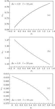
According to Eq. (39), we calculate the dependences of the reduced threshold voltage uth on the surface polarization strength p1 under different parameters. The results are shown in Fig. 1. The material parameters of LC are k11 = 13.2 pN, k33 = 18.3 pN, and Δ ε = 4.8. The thickness of the NLC cell is l = 10 μ m.
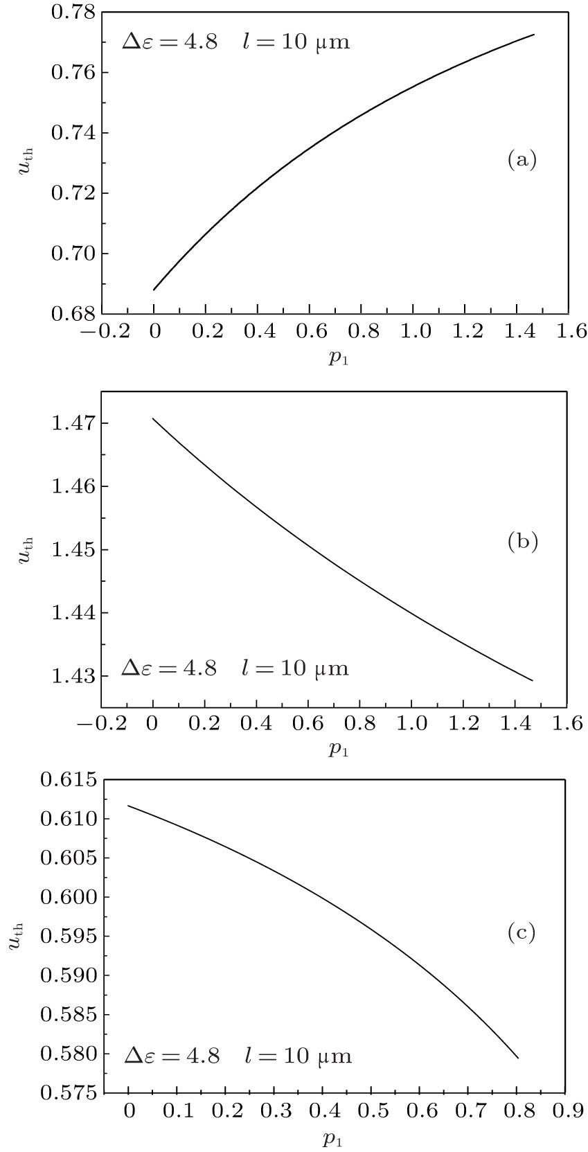 | Fig. 1. Variations of the reduced threshold voltage uth with the reduced strength of surface polarization p1 under different parameters: (a) e11 + e33 = − 4.5 × 10− 11 C/m,    |
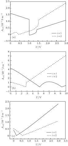
Now, we continue the discussion of the original weak anchoring HAN cell. We calculate the values of A1eff and A2eff as well as ω 1 and ω 2 with different values of U by using Eqs. (7)– (9). About the measurement of the flexoelectric coefficient, different research groups have been done using different methods.[20– 24] Even for the same kind of LC materials, the value of flexoelectric coefficient is not the same. However, Castles et al.[25, 26] have proved that the flexoelectric coefficient in NLC has a clear fundamental limit to the conventional order of magnitude of 10− 11 C/m from conservation of energy considerations. On the selection of surface polarization, we adopt the measurement value given in Ref. [27]. In order to put emphasis on the effects of two polarizations, especially the surface polarization, we adopt three sets of parameters in calculation: (i) e11 + e33 = − 45 pC/m, A1 = 1.0 × 10− 5 J/m2, A2 = 1.0 × 10− 6 J/m2, and 


 | Fig. 2. Variations of the effective anchoring strength with applied voltage. The material parameters of LC are k11 = 13.2 pN, k33 = 18.3 pN, are Δ ε = 4.8. The thickness of NLC cell is l = 10 μ m. Panels (a), (b), and (c) correspond to the three sets of parameters respectively, as given in the text. |
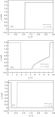
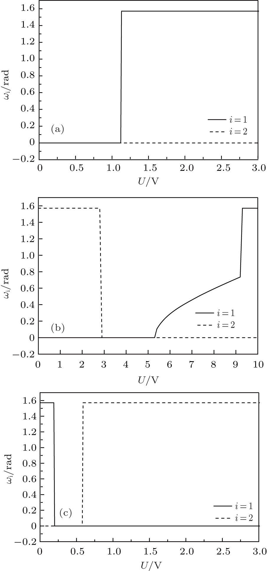 | Fig. 3. Variations of tilt angles of the effective anchoring with applied voltage. The material parameters of LC are k11 = 13.2 pN, k33 = 18.3 pN, and Δ ε = 4.8. The thickness of NLC cell is l = 10 μ m. Panels (a), (b), and (c) correspond to the three sets of parameters respectively, as given in the text. |
From these figures, we see that
1) For a small value of U, if the magnitude of surface polarization is suitable, the case both ω 1 = 0, ω 2 = 0 or π /2 may occur. Then the original HAN cell turns into a planar cell or homeotropic cell effectively, which is similar to the conclusion presented in Ref. [13]. However, if ω 1 = 0, ω 2 = π /2 or ω 1 = π /2, ω 2 = 0, the cell remains an HAN cell. 2) For a certain value of U (in a certain interval), ω 1 (or ω 2) equals a certain definite value (not including 0 and π /2), then the effective anchoring of this substrate has a pretilt angle and its maximal value is close to 42° in the cases concerned by these figures above. 3) For a large value of U, if e11 + e33 > 0, we have ω 1 = 0 and ω 2 = π /2, then it remains an HAN cell, in which the effective anchoring strengths A1eff and A2eff grow up linearly with U. However, if e11 + e33 < 0, we have ω 2 = 0 and ω 1 = π /2. Although the cell remains an HAN cell, it seems that the upper and the lower substrate are placed upside down. The effective anchoring strengths A1eff and A2eff also grow up linearly with U.
These results can be directly obtained from Tables 1 and 2 in Section 4. In spite of planar or homeotropic anchoring of a substrate, the effective anchoring may be either planar or homeotropic, or has a pretilt angle especially the magnitude of surface polarization and the value of U are suitable. It means that surface and flexoelectric polarization change the anchoring property of the substrate to produce the effective anchoring energy. Essentially, the influences of surface and flexoelectric polarization on the anchoring property of the substrate in a weak anchoring HAN cell are due to the director deformation of the surface of the substrate. So that, these two polarizations should be considered when investigating the anchoring property of the substrate in detail.
In this paper, we derived the concrete expressions of the effective anchoring energy. Both the effective anchoring strength and the corresponding easy direction are related to the magnitudes of two polarizations as well as the applied voltage. This result is obtained in the case of ignoring the adsorptive ions of the substrate surface. That is to say, the surface polarization may make a contribution to the effective anchoring energy, even in the absence of adsorptive ions, by reason that there is flexoelectric polarization.
In a factual problem, there exist not only surface and flexoelectric polarization but also the adsorptive ions. In this case, the energy term contributed by adsorptive ions as mentioned in Refs. [5], [6], and [8], should be added to the Gibbs free energy. Therefore, our work should be generalized.
Substituting Eq. (6) into Eq. (5), one can obtain
Some terms in Eq. (A1) can be denoted as the following form


Substituting Eqs. (A2)– (A7) into Eq. (A1), equation (7) and boundary conditions (8) and (9) may be obtained. Here, some terms proportional to δ 1 or δ 2 are ignored because they are very small compared with the other term. The reasons are as follows.
This term containing δ 1 can be written as
Comparing it with the term (e11 + e33)/2· (Ps1z sin 2θ 0)/g(θ 0), we can obtain
in which the term 

It is very notable that the rigorous expression of Ueff is given by
However, the latter two terms in Eq. (A10) are neglected when deducing the fundamental equation. If these two terms are considered, the boundary conditions should increase two terms Dz (∂ /∂ θ )[Ps1z/g (θ )]θ = θ 0δ 1 and Dz(∂ /∂ θ )[Ps2z/g(θ )]θ = θ lδ 2 additionally. Taking the term Dz (∂ /∂ θ )[Ps1z/g(θ )]θ = θ 0δ 1 for example, comparing it with the term [(e11 + e33)/2] · Dz · [sin 2θ 0/g(θ 0)], we can obtain

So the term Dz(∂ /∂ θ )[Ps1z/g(θ )]θ = θ 0δ 1 may be neglected. Similarly, the term Dz(∂ /∂ θ )[Ps2z/g(θ )]θ = θ lδ 2 may also be neglected.
According to the constant C for both upper and lower substrates, we have
Substituting the boundary conditions Eqs. (8) and (9) into Eq. (B1), we have
where e = (e11 + e33)/2. Introducing the following quantities: 


and

equation (B2) can be simplified into the following form:

From Eq. (B3) the expression of Dz is obtained as
For Θ 1 = 0, equation (27) can be simplified into

and equation (B2) can be simplified into
From Eqs. (24) and (28), we need to know the expression of 


Equation (B7) contains θ l, which can be determined by the following equation obtained by using Eqs. (B5) and (B6) for θ 0 = ω 1:

Substituting Eq. (B7) into Eq. (28), the expression of A1eff for ω 1 = sin− 1R1 can be obtained as
where

The selection of the sign of “ ± ” should make A1eff minimum and A1eff ≥ 0.
Adopting the same method to solve the expression of A1eff for ω 1 = sin− 1R1, the expression of A2eff for ω 2 = sin− 1R2 can be obtained as
where

The selection of the sign of “ ± ” should make A2eff minimum and A2eff ≥ 0.
Note that Δ 1 or Δ 2 may be seen as a modification of A1eff or A2eff due to 
| 1 |
|
| 2 |
|
| 3 |
|
| 4 |
|
| 5 |
|
| 6 |
|
| 7 |
|
| 8 |
|
| 9 |
|
| 10 |
|
| 11 |
|
| 12 |
|
| 13 |
|
| 14 |
|
| 15 |
|
| 16 |
|
| 17 |
|
| 18 |
|
| 19 |
|
| 20 |
|
| 21 |
|
| 22 |
|
| 23 |
|
| 24 |
|
| 25 |
|
| 26 |
|
| 27 |
|