†Corresponding author. E-mail: xiazh1006@gmail.com
‡Corresponding author. E-mail: caiqd@pku.edu.cn
*Project supported by the National Natural Science Foundation of China (Grant Nos. 11221061, 11272013, and 11302006).
A series of direct numerical simulations of the fully developed plane Couette flow at a Reynolds number of 6000 (based on the relative wall speed and half the channel height h) with different streamwise and spanwise lengths are conducted to investigate the effects of the computational box sizes on the secondary flow (SF). Our focuses are the number of counter-rotating vortex pairs and its relationship to the statistics of the mean flow and the SF in the small and moderate computational box sizes. Our results show that the number of vortex pairs is sensitive to the computational box size, and so are the slope parameter, the rate of the turbulent kinetic energy contributed by the SF, and the ratio of the kinetic energy of the SF to the total kinetic energy. However, the averaged spanwise width of each counter-rotating vortex pair in the plane Couette flow is found, for the first time, within 4(1 ± 0.25) h despite the domain sizes.
Wall-bounded turbulent flows are of great importance in both theoretical research and engineering applications. As one of the canonical problems, the turbulent plane Couette flow (PCF) (see Fig. 1) has been studied extensively.[1– 12] Unlike the pressure-driven plane channel flow, the mean pressure gradient in the PCF is zero, and the flow is driven by the shear generated at the two walls, resulting in a monotonic velocity profile and a constant shear stress distribution at all positions across the channel.
 | Fig. 1. Schematic diagram of the flow geometry of PCF. The solid line and the dotted line are mean velocity profile in a turbulence flow and a laminar flow, respectively. |
Another distinct difference from the plane channel flow is the large-scale counter-rotating streamwise vortices existing in the PCF core region. These large-scale structures (LSSs) have also been observed in experimental measurements, [13– 15] as well as in the numerical simulations.[16– 23] Based on a direct numerical simulation (DNS) of a PCF at a Reynolds number Rew = Uwh/ν (here, Uw is the velocity difference between the two surfaces, h is half the gap width, and ν is the kinematic viscosity) of 6000 and in a computational box of 4π h × 2h × 8π /3h, Lee and Kim[16] reported that there are LSSs in the core region, which are extremely long in the flow direction and fill the entire channel. They also found that these LSSs have a spanwise wavelength λ z/h ≃ 4. In addition, because the large-scale structures are persistent in space and time, Lee and Kim[16] and Papavassilious[19] approximated the large-scale structures by an SF, which represents the large eddy motion independent of time and streamwise direction. Lee and Kim reported that the SF (or the LSSs) contributes about 30% of the turbulent energy, and Papavassilious, [19] using a computational box of 4π h × 2h × 2π h, concluded that the SF accounted for up to 40% of the convective transport of streamwise momentum, indicative of the importance of the SF in energetics.
Nevertheless, because of the long persistence of the LSSs in the streamwise direction, special attention needs to be paid to the domain sizes when the PCF is studied using the numerical approaches. Bech and Andersson[17] simulated the PCF using three different DNSs at Rew = 2600 with varying computational boxes (4π h × 2h × 2π h, 16π h × 2h × 2π h, and 10π h × 2h × 4π h) and numerical resolutions. They found that the computational domain size has a great impact on the LSSs and statistics. However, the short sampling time in one of the three DNSs and the varying grid resolution weakened the reliability of the conclusions. Komminaho et al.[18] studied the effect of the computational domain on the LSSs in the PCF at Rew = 1500 using DNSs on three different domain sizes, i.e., 8h × 2h × 4h, 10π h × 2h × 4π h, and 28π h × 2h × 8π h. The final grid resolutions were kept the same, which were comparable to that in the turbulent channel flow simulation by Kim, Moin and Moser[24] in wall units. Different pairs of the LSSs were observed from their simulations with different domain sizes, and the LSSs from the simulation under the largest box were neither stationary in time nor fixed in position, in sharp contrast to the earlier observations by Lee and Kim[16] with a much smaller box. The statistical quantities for the largest box size, such as the time- and (x, z)-plane-averaged urms values, were found to converge to the value for an infinite box, indicating that a large enough box size is required to obtain a satisfactory turbulent statistics. Tsukahara et al.[20] conducted a series of DNSs of the PCF with various box sizes to investigate the LSSs in the core region. Two Reynolds numbers (Rew = 1500 and 4300) together with four different box sizes were chosen, including 48h × 2h × 12h, 64h × 2h × 16h, 89.6h × 2h × 25.6h, and 128h × 2h × 12h. They concluded that the meandering of the LSSs could be captured with a long box size (Lx ≳ 64h) in the core region, and the length scale in the spanwise direction should be at least 16h to avoid the LSSs being strictly confined by the periodic boundary conditions. Also, they observed that the LSSs, which are made up of counter-rotating streamwise vortex pairs, occupy the whole channel, in agreement with the previous reported results. Although more and more DNSs have been conducted to simulate the PCF nowadays, the influence of the computational domain size upon the LSSs and upon the statistics is not yet completely understood.
To gain more insight into the role which LSSs play in the PCF, it is significant to pay attention to the SF. In the present work, a series of DNSs of the PCF with different computational box lengths have been carried out to examine their effects on the SF. The DNS of the PCF in the large box size is so expensive that it is important and necessary to study the SF behavior and the statistics of the PCF in the small or moderate box size, which may help to predict the turbulent behavior in the large computational domain. Therefore, unlike the previous pioneering studies, the computational domains in the present study are limited to small and moderate sizes, and our focuses are the number of counter-rotating vortex pairs and its relationship to the statistics of the mean flow and the SF. The paper is organized as follows. Details on the numerical procedures are provided in Section 2. Results of the simulation of the PCF are discussed in Section 3, and conclusions are finally provided in Section 4.
In the simulations, the bottom wall is fixed, while the upper wall is moved in the streamwise direction at speed Uw (see Fig. 1). The incompressible Navier– Stokes equations are solved using the well-known KMM method, [24] a pseudo-spectral method with Fourier and Chebyshev polynomial expansions in the streamwise and spanwise (x, z) and wall-normal (y) directions, respectively. The equations are integrated in time by using a semi-implicit scheme: a second-order Adams– Bashforth scheme for the nonlinear term and a second-order Crank– Nicolson scheme for the linear term. The nonlinear term is dealiased by using a 3/2-truncation rule. No-slip condition is used at the walls, and periodic boundary conditions are employed in the horizontal directions.
In Table 1, we list the parameters of the simulations at Rew = 6000. Eight computational cases with different streamwise lengths Lx and different spanwise widths Lz are simulated with the same resolutions, which are very close to those used by Lee and Kim.[16] The relative friction Reynolds number is Reτ = uτ h/ν ≈ 170, where 
| Table 1. Parameters of the simulations at Rew = 6000. Lx and Lz are the streamwise and spanwise lengths of the numerical box, respectively. Reτ = uτ δ /v is the Reynolds number based on friction velocity uτ . Nx, Ny, and Nz are the number of collocation points, and Ny = 128 for all cases. Δ x+ and Δ z+ are the spatial resolution. UwT/Lx is the sampling time. |
Generally, in the research of turbulence, the instantaneous velocity ui is decomposed into the mean flow 〈 ui〉 , where 〈 · 〉 denotes the time- and (x, z)-plane-average scheme, and the fluctuation velocity 

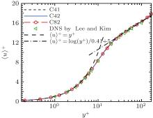
We display the normalized mean velocity profiles in wall scales from the cases C41, C42, and C82 in Fig. 2, as well as that from Lee and Kim.[16] It is apparent that the velocity profiles from the three cases agree very well with that from Lee and Kim, indicating that the present code and simulations are reliable.
 | Fig. 2. Mean streamwise velocity profile normalized by uτ for case C41 (dashed-line), C42 (solid-line), C82 (long-dashed-line with circles), and by Lee and Kim[16] (ᐊ ). The long dashed-line and dash– dotted line denote the law of wall: 〈 u〉 + = y+ and 〈 u〉 + = log(y+ )/κ + B, respectively, where κ = 0.41 and B = 5.0. |
In the present paper, for investigating the characteristics associated with the SF (or the large-eddy motions), the instantaneous velocity ui is decomposed by a triple-decomposition approach[16, 19]

Here, 


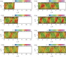
In Fig. 3, the SF for eight cases are shown in the yz-plane, and the counter-rotating vortex pairs can be counted clearly. As Lee and Kim reported, the large-scale eddies are indeed so large that they fill the whole channel. By getting results from Fig. 3, the number of vortex pairs Nvp and a vortex wavelength (or mean spanwise scale of vortex pairs) λ z = Lz/Nvp for eight cases are summarized in Table 2. In addition, it indicates that the number of the vortex pairs is sensitive to the computational box size, and it may highly influence the statistics of turbulence. On the other hand, let us consider cases C22, C42, and C82 which have the same spanwise width Lz = 2π h. For case C82, the velocity vectors of the secondary flow are very neat. However, for cases C22 and C42, the secondary flows are not smooth, even though the velocity fields are averaged over a double period of the sampling time (as listed in Table 1). We prefer to attribute this non-smooth behavior of the secondary flows to the unfavorable domain size which may prevent the formation of persistent vortices.[25]
 | Fig. 3. Velocity vectors of the SF, (vs, ws), and streamwise vorticity, ω x, in the yz-plane for eight computational cases (as listed in Table 1). |
| Table 2. The number of vortex pairs Nvp and the averaged width λ z = Lz/Nvp of each pair for all the cases. L-K is the result from Lee and Kim, [16] K-L-J are the results from Komminaho et al., [18] A-H-O-G is the result from Avsarkisov et al., [22] B-P-O is the result from Bernardini et al., [12] and N-A-P is the result from Narasimhamurthy et al.[28] All quantities are normalized by h. |
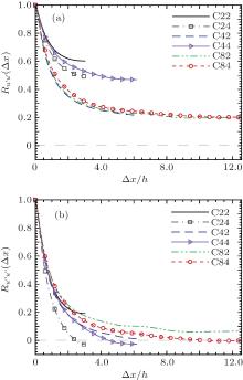
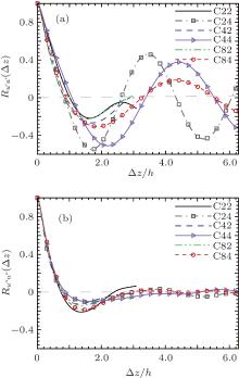
Generally, the influence of box size on the LSSs can be observed by the two-point streamwise correlation for the streamwise fluctuation velocity Ru′ u′ (Δ x). Besides, in the present paper, the two-point streamwise correlation for the streamwise velocity of residual field Ru″ u″ (Δ x) is applied to study the effect of the SF. We plot Ru′ u′ (Δ x) and Ru″ u″ (Δ x), at the centerline, in Fig. 4(a) and Fig. 4(b), respectively, for six cases (case C22, C24, C42, C44, C82, and C84).


As shown in Fig. 4(a), Ru′ u′ (Δ x) for six cases all remain positive at the mid box length because of the small box size. In Fig. 4(b), Ru″ u″ (Δ x) for six cases are all obviously smaller than Ru′ u′ (Δ x), and, specially, Ru″ u″ (Δ x) for cases C24, C44, and C84 reach negative at the mid box length. It indicates that there is a strong secondary flow in the PCF. In addition, Ru′ u′ (Δ x) for case C84 is smaller than Ru′ u′ (Δ x) for case C44 which has the same spanwise computational width as case C84, while Ru′ u′ (Δ x) for cases C42 and C82 are almost equal. It means that, on the condition of the wider computational width Lz, we need to compute with the longer computational length Lx to capture the one period of the streamwise structure. What is more, Ru′ u′ (Δ x) for cases C42, C82, and C84 almost collapse, and Ru′ u′ (Δ x) for cases C82 and C84 are constant when Δ x is larger than 10h. Therefore, we predict that, for the computational widths of 2π h and 4π h, the two-point streamwise correlation Ru′ u′ (Δ x) cannot reach the negative at the mid box length, even though the computational length is much longer than 8π h. It indicates that the box width Lz must be long enough, at least larger than 4π h, to ensure that we can capture the one period of the streamwise structure.
The two-point spanwise correlations Ru′ u′ (Δ z) and Ru″ u″ (Δ z), at the center of the channel, are given in Fig. 5(a) and Fig. 5(b), respectively. In Fig. 5(a), the strongest minimum of Ru′ u′ (Δ z) for cases C24 and C44 are smaller than that for case C84, which verifies that a long box length Lx is necessary to weaken the effect of the periodic boundary condition, and it leads to a reduction of the spanwise correlation for the LSSs. The magnitude of Ru″ u″ (Δ z) is much smaller than that of Ru′ u′ (Δ z), as shown in Fig. 5(b), by which we confirm there is a strong secondary flow in the PCF.
The normalized velocity gradient at the centerline (CL), also called the slope parameter, defined as

is a characteristic parameter of the PCF, which is a measurement of the mean velocity field to a certain degree. However, its dependence on the Reynolds number is still an open question in the PCF.[22] The value of Ψ at infinite Reynolds number was suggested to be 0.25 by Busse, [26] and 0 by Lund and Bush, [27] respectively. On the other hand, several experiments and DNSs at low Reynolds numbers or with very small boxes suggested the values are close to the range 0.18– 0.2.[13, 18, 20] Avsarkisov et al.[22] found a clear decrease trend of this value, with Ψ = 0.18, 0.16, 0.14, and 0.1 for Rew = 4500, 6300, 9000, and 22500. In the present simulations, we simulated one Reynolds number, and Ψ should be a single value in a large enough computational domain. However, because of the strong and unsteady behavior of the SF, at the same Reynolds number, the values of Ψ are scattered within a range of 0.090– 0.207 in the small computational domains, as listed in Table 1.
Under the triple-decomposition, the total kinetic energy K ≡ 〈 uiui〉 /2 (the repeated subscripts imply summation) can be decomposed into three parts, similarly:

i.e., the kinetic energy of the mean flow 〈 ui〉 〈 ui〉 /2, the kinetic energy of the SF 


In order to study the importance of the SF in energetic, we further define two parameters:


i.e., the rate of the turbulent kinetic energy contributed by the SF and the ratio of the kinetic energy of the SF to the total kinetic energy. The values of Rks/k and Rks/K from our simulations are listed in the last two columns of Table 1. Similar to the slope parameter, these two ratios are scattered, within the range of 0.067– 0.305, and 0.00145– 0.00685, respectively. Lee and Kim[16] reported that Rks/k ∼ 30%, and the case of C43, which employs a similar computational box, has the closest value of Rks/k ≃ 30.5%. Through the statistics of Rks/k, it indicates that the rate of the turbulent kinetic energy contributed by the SF is much lower than 30% in the large computational domain.
Since the total input of the PCF is the momentum from the upper moving wall, which is a constant, the total kinetic energy should be the same at the fully developed state. In particular, in the cases of C22, C42, and C82, the values of Rks/K decrease as Lx increases, and this could be explained by the fact that the self-amplification mechanism becomes weaker as Lx increases, as pointed out by Komminaho[18] and Andersson, [9] which results in weakened large-eddy motions. However, the above-mentioned dependence on Lx is not exactly true for the cases C24, C44, and C84, but it is true for the cases C44 and C84. The reason can be related to the different numbers of the counter-rotating vortex pairs in the cases C24, C44, and C84 (see Table 2). Different spanwise and streamwise lengths will obtain different numbers of the counter-rotating vortex pairs in the simulation of PCF, resulting in different intensities of the SF. This is exactly the reason for the unclear dependence of the values of Rks/K on Lz.
Clearly, the statistical quantities discussed above, i.e., the slope parameter, Rks/K and Rks/k, are not convergent in the present simulations and are highly influenced by the computational domain size, which may be affected by the SF primarily. It is expected, at least intuitively, that more pairs of counter-rotating vortices (a manifestation of the SF) could be obtained if the spanwise length of the computational box was wider. Earlier simulations by Kimminaho et al.[18] observed one pair of counter-rotating vortices when the domain was 8h × 2h × 4h, and six pairs when the domain was 28π h × 2h × 8π h. In the present simulations, we also get different pairs of counter-rotating vortices with different computational boxes. In Table 2, we list the number of vortex pairs Nvp and the average width λ z of vortex pairs from all the present simulations, as well as the data from previous simulations, including those from Lee and Kim, [16] Komminaho et al., [18] Avsarkisov et al., [22] Bernardini et al., [12] and Narasimhamurthy et al.[28]
In Fig. 6(a), we plot the number of vortex pairs Nvp from all the data, listed in Table 2. As discussed above, more pairs of counter-rotating vortices are obtained with a wider spanwise width of the computational domain, as expected, except case C24, where four pairs of vortices are observed with Lx = 2π h and Lz = 4π h. This means that the streamwise length may also influence the SF to some extent.
The averaged spanwise width of each counter-rotating pair λ z = Lz/Nvp varies within a certain range 4(1 ± 0.25)h, despite the computational box size, as shown in Fig. 6(b), where the normalized averaged width of each vortex pair λ z/(4h) is shown as a function of the streamwise length Lx/h/π . In the PCF, the large-scale eddies fill the entire channel, and the height of the counter-rotating vortex pair is 2h. If the averaged width of each large-eddy was 2h, then the large-eddy had equal width and height, approximating to a circle shape. The averaged spanwise width of each pair is 4(1 ± 0.25)h, i.e., the averaged spanwise width of each vortex is 2(1 ± 0.25)h, indicating that the large-eddies are inclined to the circle shape in all the cases. In fact, in free-shear flow problems without solid boundaries, the large-eddy or vortex tends to a circle shape due to the centrifugal force. Because of the existence of the wall (non-slip boundary conditions), the large-eddies in the PCF show a little variance.
In the present work, a series of DNSs of the fully developed PCF at Reynolds number Rew = 6000 with different streamwise and spanwise lengths are conducted to investigate the effect of the computational box sizes on the SF. Our focuses are the number of counter-rotating vortex pairs and its relationship to the statistics of the mean flow and the SF under small and moderate computational box sizes. The results lead to the following conclusions.
(i) The number of the counter-rotating vortex pairs is sensitive to the computational box sizes, and so are the slope parameter, the rate of the turbulent kinetic energy contributed by the SF, and the ratio of the kinetic energy of the secondary to the total kinetic energy. It is exactly indicated that no convergent conclusion could be made for the PCF using the different small box sizes, which is caused by the strong and unsteady behavior of the SF.
(ii) Based on the data from the present simulations and the previous available DNSs, the averaged spanwise width of each counter-rotating vortex pair in the PCF is found, for the first time, within 4(1 ± 0.25)h despite the domain sizes.
Clearly, the different computational box sizes result in different large-scale vortex structures and different statistical quantities of the PCF. In the future, we will study the underlying reason for relationship between the SF and the computational box sizes.
| 1 |
|
| 2 |
|
| 3 |
|
| 4 |
|
| 5 |
|
| 6 |
|
| 7 |
|
| 8 |
|
| 9 |
|
| 10 |
|
| 11 |
|
| 12 |
|
| 13 | [Cited within:2] |
| 14 |
|
| 15 |
|
| 16 |
|
| 17 |
|
| 18 |
|
| 19 |
|
| 20 |
|
| 21 |
|
| 22 |
|
| 23 |
|
| 24 |
|
| 25 |
|
| 26 |
|
| 27 |
|
| 28 |
|
| 29 | [Cited within:1] |


