†Corresponding author. E-mail: yandawangjinjin@163.com
*Project supported by the National Natural Science Foundation of China (Grant No. 61104040), the Natural Science Foundation of Hebei Province, China (Grant No. E2012203090), and the University Innovation Team of Hebei Province Leading Talent Cultivation Project, China (Grant No. LJRC013).
In the present work, we investigate the nonlinear parametrically excited vibration and active control of a gear pair system involving backlash, time-varying meshing stiffness and static transmission error. Firstly, a gear pair model is established in a strongly nonlinear form, and its nonlinear vibration characteristics are systematically investigated through different approaches. Several complicated phenomena such as period doubling bifurcation, anti period doubling bifurcation and chaos can be observed under the internal parametric excitation. Then, an active compensation controller is designed to suppress the vibration, including the chaos. Finally, the effectiveness of the proposed controller is verified numerically.
Gears are widely used in mechanical systems and are known as one of the main sources of noise and vibration. Therefore, there is important theoretical and practical value in investigating the vibration characteristics in a gear system.
In the past 30 years, the nonlinear vibration of the gear system has been extensively studied, [1– 5] and some complicated phenomena such as bifurcation and chaos have been observed. In Ref. [6], the nonlinear frequency responses of a spur gear pair with backlash were investigated through the harmonic balance method. In Refs. [7] and [8], some experiments were performed on the gear pair system, and several phenomena such as sub-harmonic resonance, super-harmonic resonance and chaotic behaviors have been observed. In Ref. [9], a nonlinear geared rotor-bearing system was studied, and the periodic responses and bifurcations were investigated. Moreover, the chaotic response was examined by using numerical methods and the Lyapunov exponent. In Ref. [10], a nonlinear model of a gear system involving friction, backlash, and time-varying stiffness was studied, and the existence of periodic responses, bifurcation and chaotic motions were investigated numerically. In Ref. [11], the frequency responses of a nonlinear geared rotor-bearing system with time-varying meshing stiffness were examined through the method of multiple scales and digital simulation. In Ref. [12], the vibration dynamic responses of a gear pair system supported by journal bearing were investigated, and the existence of periodic, sub-harmonic and chaotic states were examined numerically. In Refs. [13] and [14], a survey of the nonlinear vibration in the gear transmission systems was made, and the progress in nonlinear dynamics of gear transmission systems in the past twenty years was reviewed, especially the nonlinear dynamic behaviors of the gear system with considering the backlash and time-varying meshing stiffness. In addition, the researches on dynamic behaviours of relative rotation nonlinear dynamic system can also serve as examples.[15– 20]
Exactly speaking, the gear system is a kind of strongly nonlinear system with parametric excitation. Therefore, it can exhibit complex vibration even though the external incentive is zero. As the vibration can reduce the performance of the transmission system, the vibration control has been an important research topic.[21– 23] Based on the Melnikov method, a non-feedback control method was used to eliminate the chaos in the gear system by applying an additional control excitation.[24] In Ref. [25], a control scheme in which three magnetostrictive actuators are used mounted on the gear to produce circumferential forces for suppressing the torsional vibrations was proposed. Moreover, the researches on active vibration control of the gearbox can also serve as examples.[26– 28]
As mentioned above, a mass of valuable researches has been carried out on the gear pair system, and some complicated nonlinear phenomena were observed. However, the nonlinear parametrically excited vibration of the gear system has rarely been investigated systematically. Since the gear system is a kind of strongly nonlinear system with parametric excitation and the parametric excitation can strongly influence the vibration dynamics of the gear system, it is essential to investigate this factor. As for the vibration control mentioned above, most of them are passive control. Although they are widely used, they cannot suppress the vibration effectively, for which the main reason is that the passive control cannot essentially eliminate the factors which can cause the vibration. According to the discussion above, in the present paper, we investigate the nonlinear parametrically excited vibration to reveal the essence of the occurrence of nonlinear vibration in a gear pair system. In addition, an active compensation controller is designed to suppress the vibration.
The rest of the paper is organized as follows. In Section 2, a nonlinear gear pair model is briefly presented. In Section 3, the nonlinear parametrically excited vibration of the gear pair system is systematically investigated. In Section 4, an active compensation controller is designed based on the active disturbance rejection control technique. In Section 5, some numerical simulations are carried out to validate the proposed controller. Finally, some conclusions are drawn from the present study in Section 6.
In the present paper, we investigate a gear pair system involving backlash, time-varying meshing stiffness and static transmission error, and the corresponding torsional vibration model is shown in Fig. 1.
By Newton’ s theorem, the balance equation for the driving and driven gears can be obtained as


where Ip and Ig are the rotational inertia of the drive and driven gears respectively, θ p and θ g represent the angular displacements of drive and driven gears respectively, Rp and Rb are the base radii of the drive and driven gears respectively, Tp and Tg represent the input torque and load torque respectively, C represents the meshing damping along the line of action, k(t) is the time-varying meshing stiffness, and e(t) is the static transmission error.
In order to investigate the torsinal vibration of the gear pair system, let x = Rpθ p − Rgθ g − e(t), then equations (1) and (2) will be transformed into

where 

with 2b representing the total backlash.
For the gear pair system (4), both the meshing stiffness and the static transmission error quantities can approximately be considered as time-periodic functions. In addition, if the tooth-to-tooth variations are neglected, [1] the fundamental frequencies of these quantities are both equal to the gear meshing frequency, which implies that the meshing stiffness and the static transmission error terms can be expressed as a Fourier series form. Without loss of generality, they are chosen as k(t) = k0 + k1 cos(ω ht) and e(t) = em cos(ω ht).
Next, introduce the following parameters: 


In Eq. (4), the symbol τ has been replaced by t for simplicity, where, k(t) = 1 + k1 cos(ω t), fav = Fav/bk0, fe = em/b, and

The gear pair system investigated in this paper contains not only the backlash but also the time-varying stiffness and static transmission error which make it a kind of strongly nonlinear system with parametric excitation. Therefore, the system will exhibit various multi-frequency responses even though under a single-frequency excitation, including the main frequency response, sub-harmonic and super-harmonic resonances. Under certain conditions, the chaotic behavior may occur.
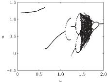
In order to analyze the effects of the parametric excitation on the vibration of gear pair system (4), the system parameters are chosen as follows: ξ = 0.06, k1 = 0.06, fe = 0.25, and fav = 0.2, then the bifurcation diagram with the meshing frequency ω varying is obtained as shown in Fig. 2.
From the bifurcation diagram, different forms of vibration, including the periodic-1 vibration, periodic-n vibration (n > 1) and chaotic behavior can be observed under the varying meshing frequency. Herein, in order to accurately determine the chaotic behavior, the corresponding Maximal Lyapunov exponent is also presented as shown in Fig. 3.
In combination with the bifurcation diagram and the Maximal Lyapunov exponent spectrum, the whole meshing frequency band of the gear pair system (4) can be divided into five parts, and they are defined as band 1 (ω ∈ [0.1, 0.64]), band 2 (ω ∈ [0.64, 1]), band 3 (ω ∈ [1, 1.5]), band 4 (ω ∈ [1.5, 1.75]), and band 5 (ω ∈ [1.75, 2]). The vibration characteristic in each frequency band will be briefly discussed.
From the bifurcation diagram, periodic-1 vibration can be observed in frequency band 1, i.e., ω ∈ [0.1, 0.64]. Choose ω = 0.5, then the corresponding time history, phase diagram and Poincare section can be obtained as shown in Fig. 4. Obviously the system is under the meshing state with vibration.
In frequency band 2, i.e., ω ∈ [0.64, 1], choose ω = 0.8, then the time history, phase diagram and Poincare section of the system will be obtained as shown in Fig. 5. In this case, the single-sided impact occurs, which will lead to serious noise.
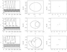
With the increase of meshing frequency, rich dynamic behaviors can be found in frequency band 3, i.e., ω ∈ [1, 1.5]. The period doubling bifurcation is observed, and the periodic-1 vibration turns into periodic-n vibration (n > 1). Choose ω = 1, 1.2, 1.4, then the corresponding time history, phase diagram and Poincare section will be obtained as shown in Fig. 6.
In combination with the bifurcation diagram and the Maximal Lyapunov exponent spectrum, the chaotic behavior can be observed in frequency band 4, i.e., ω ∈ [1.5, 1.75]. Choose ω = 1.6, then the corresponding time history, phase diagram and Poincare section are obtained as shown in Fig. 7.
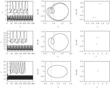
The anti period doubling bifurcation will occur when the meshing frequency belongs to frequency band 5, i.e., ω ∈ [1.75, 2], and the chaotic state will disappear in this band. Choose ω = 1.75, 1.8, 2, then the detailed transient are sketched as shown in Fig. 8.
From the above investigation, various nonlinear vibrations can be observed with the increase of meshing frequency. The initial periodic-1 vibration turns into periodic-n vibration and chaos through the period doubling bifurcation, then the chaotic state will turn into periodic-1 vibration through the anti period doubling bifurcation. Meanwhile, the vibration frequency will increase.
The varying meshing frequency will directly lead to the change of the time-varying meshing stiffness and static transmission error, namely the parametric excitation. Hence, we can obtain a conclusion as follows: the parametric excitation can lead to complex nonlinear vibration, which will reduce the performance of the gear transmission system. Therefore, it is essential to eliminate this internal incentive for suppressing the vibration in the gear pair system.
In this section, an active compensation controller will be designed based on the active disturbance rejection control technique to supress the nonlinear parametrically excited vibration of gear pair system (4).
As the parametric excitation in the gear system (4) can be regarded as a kind of time-varying disturbance, system (4) can be expressed as

where f (u, t) = feω 2 cos(ω t) − k1 cos(ω t)f (u). So, the gear pair system can be regarded as a kind of piecewise system with time-varying disturbance.
Suppose x1 = u and x2 = u̇ , then the system will be expressed as

where f (x1, t) represents the inherent internal time-varying disturbance feω 2 cos(ω t) − k1 cos(ω t) f (x1).
Add a control variable u to system (6), then the resulting equation will be expressed as

In order to adopt the active disturbance rejection control technique, the time-varying disturbance f (x1, t) should be extended as a new state variable,

And suppose ẋ 3 = g(t), then system (7) will be extended as a new linear control system as expressed by

For system (9), based on the active disturbance rejection control technique, the controller can be designed as

where fal(e, α , δ ) is a special nonlinear feedback function, and can be expressed as

For the controller designed above, the β 1, β 2, and β 3 are the gain parameters. According to the analytical and numerical study, they are generally determined by the integral step h, and the integral step is determined by the range of the estimated object, i.e., the range of f (x1, t). If the estimated system is more sensitive and fast, a small integral step is essential. Only if h is determined, can the β 1, β 2, and β 3 be chosen according to the following principle.
The β 1 is inverse to integral step h, i.e., β 1 = 1/h, and β 2, β 3 can be chosen as 1/3h2, 1/82h3 respectively. In addition, a larger β 3 can make the estimation error smaller and the speed faster, but an oscillation may occur. Meanwhile, a larger β 2 can also lead to an oscillation. Therefore they should be adjusted according to the system.
The principle given above can only serve as a reference. In a specific design, they should be coordinately adjusted to meet the requirement.
In this section, the effectiveness of the designed controller (10) will be verified by numerical simulation. Choose the controller parameters to be h = 0.01, α 1 = α 2 = 0.5, δ 1 = 0.05, δ 2 = 0.25, β 1 = 1/h = 100, β 2 = 1200, and β 3 = 5 × 10⁴.
Firstly, the observation effect for system state variables x1, x2, and x3 in the five frequency bands are presented to prepare for the control effect for nonlinear vibration. For the five defined frequency bands above, choose ω = 0.5, 0.8, 1.4, 1.6, 2 as the representation of each frequency band. Then the designed controller can be used to estimate the system state variables x1, x2, and x3 as shown in Fig. 9, respectively.
From the observation renderings shown in Fig. 9, the controller can accurately estimate the system state variables x1, x2, x3 in the five frequency bands, which makes an important foundation for suppressing the nonlinear parametrically excited vibration of the gear pair system.
In order to verify the control effect for vibration, the controller is adopted in each frequency band. Then the control effect can be obtained by comparing the uncontrolled system with the controlled system.
Still choose ω = 0.5, 0.8, 1.4, 1.6, 2 as the representation of the five frequency bands respectively, and adopt the controller parameters as follows: h = 0.01, α 1 = α 2 = 0.5, δ 1 = 0.05, δ 2 = 0.25, β 1 = 1/h = 100, β 2 = 1200, β 3 = 5 × 10⁴, then the dynamic responses of controlled (c) and uncontrolled (uc) system will be obtained (see Fig. 10).
 | Fig. 10. Control effects in each frequency band. |
By observing the control effect for nonlinear vibration in each frequency band, a conclusion can be obtained as follows: the designed controller can suppress the nonlinear vibration of the gear pair system in each frequency band, and make the gears in a meshing state, which greatly reduces the damage and noise caused by the collision of gears, and in the five frequency bands, the controller parameters remain the same, which implies that the controller is robust.
In the present work, we investigate the nonlinear parametrically excited vibration and its active control of a gear pair system involving backlash, time-varying meshing stiffness and static transmission error. Firstly, the influence of the meshing frequency on the nonlinear vibration in the gear system is systematically investigated by different approaches, including the bifurcation diagram, the Lyapunov index method, phase diagram and Poincare section, and some complicated phenomena such as period doubling bifurcation, anti period doubling bifurcation and chaos are observed. These studies reveal that the parametric excitation is the direct factor which can lead to complex nonlinear vibration. In addition, an active compensation controller is designed to suppress the vibration, and the rationality and robustness of the controller are verified numerically.
The researches in this paper can not only make us have a better understanding of the nonlinear vibration in gear systems, but also provide us with an effective control strategy to suppress the vibration in gear transmission systems.
| 1 |
|
| 2 |
|
| 3 |
|
| 4 |
|
| 5 |
|
| 6 |
|
| 7 |
|
| 8 |
|
| 9 |
|
| 10 |
|
| 11 |
|
| 12 |
|
| 13 |
|
| 14 |
|
| 15 |
|
| 16 |
|
| 17 |
|
| 18 |
|
| 19 |
|
| 20 |
|
| 21 |
|
| 22 |
|
| 23 |
|
| 24 |
|
| 25 |
|
| 26 |
|
| 27 |
|
| 28 |
|


