

Broadband and high-speed swept external-cavity laser using a quantum-dot superluminescent diode as gain device
[Hu Fa-Jie, Jin Peng† , Wu Yan-Hua, Wang Fei-Fei, Wei Heng, Wang Zhan-Guo]
, Wu Yan-Hua, Wang Fei-Fei, Wei Heng, Wang Zhan-Guo]
|
|


†Corresponding author. E-mail: pengjin@semi.ac.cn
*Project supported by the National Natural Science Foundation of China (Grant No. 61274072) and the National High Technology Research and Development Program of China (Grant No. 2013AA014201).
A wide wavelength tuning range swept external-cavity laser using an InAs/GaAs quantum-dot superluminescent diode as a gain device is demonstrated. The tunable filter consists of a polygon scanner and a grating in Littrow telescope-less configuration. The swept laser generates greater than 54-mW peak output power and up to 33-kHz sweep rate with a sweep range of 150 nm centered at 1155 nm. The effects of injection current and sweep rate on the sweep performance of the swept laser are studied.
Swept laser as an important kind of coherent light source can find applications in many fields, such as swept source optical coherence tomography (SS-OCT), [1] optical reflectometry, [2] fiber sensor systems, [3] and gas sensing.[4] Among these applications, the new generation of OCT based on swept laser attracts a great deal of attention. In the case of SS-OCT, the key parameters include a high sweep rate for a fast imaging speed, a wide tuning range for a high spatial resolution, a narrow instantaneous linewidth for a large ranging depth and enough output power for high sensitivity. Since the first swept laser was developed by the researchers of Massachusetts Institute of Technology (MIT) in 1997, [1] considerable effort has been devoted to investigations of the high performance swept laser for SS-OCT application. Wide tuning ranges over 150 nm have been realized by employing rapidly tuning elements such as grating/galvanometer tunable filter, grating/polygon mirror tunable filter, fiber Fabry– Perot tunable filter, electro-optics tunable filter, etc.[5– 17] In 2006, a long cavity configuration called Fourier domain mode locking (FDML) was developed to achieve extremely fast sweep speed.[18] Recently, a method of dispersion tuning was demonstrated to overcome the limits of the mechanically tunable filter.[19– 22] However, the gain medium used in these swept lasers is mainly the quantum well semiconductor optical amplifier (SOA), and in the present study we use a quantum-dot superluminescent diode (QD-SLD) as the gain device. The quantum dot (QD) gain device has advantages for realizing a wide tuning range which is expected to meet the requirement for SS-OCT. The characteristic of size inhomogeneity occurring in self-assembled quantum dot material is beneficial to broadening the gain spectrum.[23– 31] With low ground state density, the gain spectrum is easily extended by filling to the higher state.[32] Therefore, the QD gain device is suitable for broadband swept laser.
In this paper, we construct a wide wavelength tuning range swept external-cavity (EC) laser based on the grating/polygon mirror tunable filter and employed QD-SLD as a gain device. The characteristics of the free-running quantum-dot gain device are investigated. The measured wavelength tuning range of the swept laser is 150 nm with a peak output power greater than 54 mW and up to 33-kHz sweep rate. The effects of injection current and sweep rate on the sweep performance of the swept laser are also studied.
The epitaxial structure of the QD gain device in this study was grown by a Riber 32P solid-source molecular beam epitaxy machine on n-GaAs (001) substrate. The active region was embedded in a waveguide, contained eleven layers of self-assembled InAs QDs covered by an In0.15Ga0.85As cap layer with different thickness values and separated from the adjacent QD layers by a 35-nm GaAs spacer layer. Each QD layer was formed by depositing 2-monolayer InAs at 490 ° C. Below and above the waveguide were 1.5-μ m n- and p-type Al0.5Ga0.5As cladding layers, respectively. Finally, a 250-nm thick p+ -GaAs layer was capped as an Ohmic contact layer. Then the QD epitaxial wafer was processed to fabricate the gain device of a J-shape bent-waveguide structure. The bent-waveguide facet was coated with SiO2/Ta2O5 double anti-reflection (AR) layers to minimize reflectivity at 1170 nm while the straight-waveguide facet remained as-cleaved. The device was mounted p-side down on a copper heat sink.
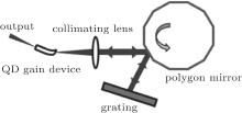
Figure 1 shows the schematic of the EC swept QD laser, which was constructed with a Littrow configuration. The aspherical lens with a numerical aperture of 0.55 was fit for a divergence angle of the QD device. The optical tunable filter consisted of a 600-grooves/mm grating and a polygon scanner with 36 facets. The polygonal mirror was coated with protected gold and the reflectivity exceeded 94% across the spectrum ranging from 0.7 μ m to 10 μ m. The external cavity length in the design was about 30 cm. The light emission from the bent-waveguide facet was collimated by the aspherical lens and was incident onto the optical filter, in which the reflected light from the polygonal mirror illuminated the grating and retraced back in its first diffraction order to the device. The emission from the straight waveguide facet was taken as the output of the swept laser. The wavelength tuning of the laser was achieved by rotating the polygonal mirror; one complete wavelength sweep was accomplished for each rotation of a polygonal mirror facet through an angle of 10° . The free spectral range (FSR) of this tuning filter is given by the following equation:[13]

where p, Δ α , and α 0 represent the grating pitch, the sweep angle (Δ α = 4π /N, with N being the number of facets), and the incident angle at the central wavelength respectively. In this work, the experimental parameters were as follows: p = 1/600 mm, Δ α = 20° , α 0 = 20° . So the theoretical FSR calculated with these parameters was 1093 nm. The sweep speeds used in the experiment were 6 kHz, 12 kHz, 24 kHz, and 33 kHz. The output characteristics were obtained under continuous-wave (CW) current injection at room temperature.
 | Fig. 1. Schematic diagram of the EC swept QD laser based on the Littrow configuration. |
Before performing the EC sweeping experiment, the emission spectra of the free-running QD device at various injection levels are measured from the bent-waveguide facet as shown in Fig. 2(a). Lasing is not observed even when the injection current is increased up to 1000 mA, showing a typical superluminescent behavior for the self-assembled QD gain device. There exists an obvious blue shift of emission spectrum with the current increasing from 20 mA to 1000 mA. This phenomenon can be attributed to the inhomogeneity of the distribution of QD sizes and the effect of carriers filling sequentially from the low to high energy states. At a low injection current of 20 mA, the peak of the emission spectrum is 1253 nm with a full width at half maximum (FWHM) of 54.1 nm which is dominated by the QD ground state (GS) transition. With the injection level increasing, the GS emission is gradually saturated and the carriers filling in the QD excited states (ESs), therefore the emission spectrum extends to a short wavelength region. At the current of 1000 mA, multiple energy state transitions of QDs contribute to the spectrum emission, and the FWHM of 66.6 nm is obtained. Figure 2(b) shows an output power-injection current (P– I) curve of the free-running QD gain device. A maximum output power of 30 mW under 1000-mA injection is achieved.
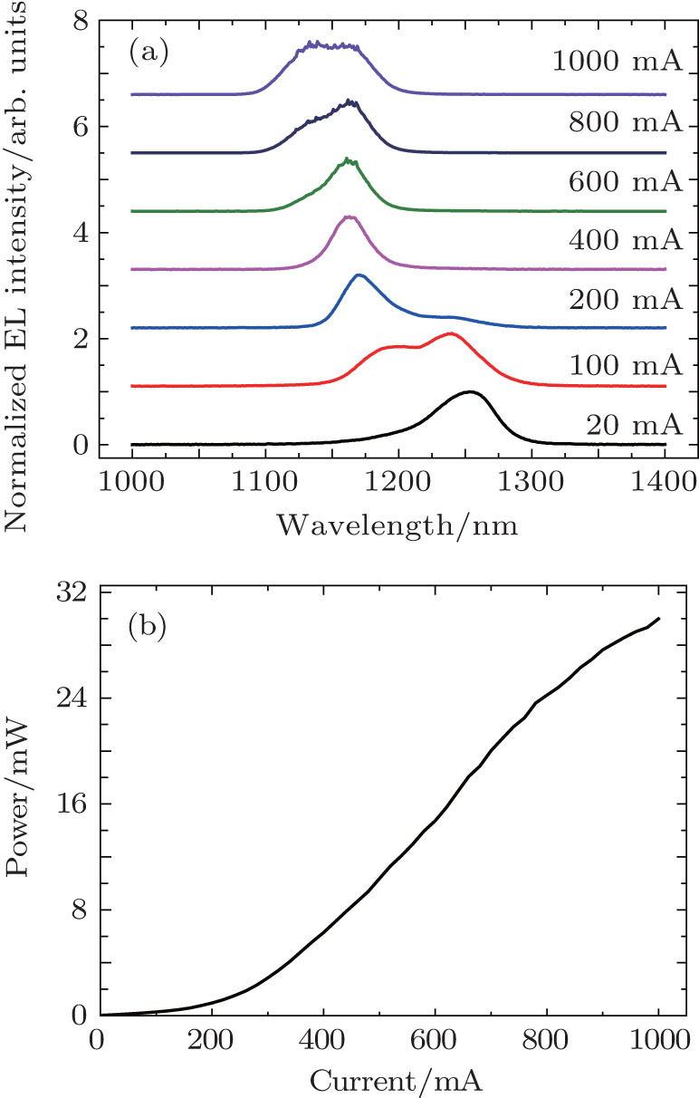 | Fig. 2. (a) Normalized emission spectra of the free-running QD gain device under different injection currents and (b) output power-injection current (P– I) curve of the free-running QD gain device. |
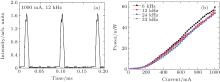
Figure 3 shows the dynamic characteristics of the swept laser. At a given time, the EC lasing is formed between the grating and the straight-waveguide facet of the QD gain device. The wavelength sweeping is realized by rotating the polygonal mirror. The output spectra depending on the applied current of the QD gain device are measured as shown in Fig. 3(a), which is operated at the 12-kHz sweep rate. The tuning range obviously broadens with the increase of injection current especially on the short-wavelength side and it is in accordance with the spectra of the free-running QD gain device due to the sequential carrier filling in the energy states of the self-assembled QDs. A maximum sweep range of 150.4 nm (1079.9 nm– 1230.3 nm) under a current of 1000 mA is obtained. Figure 3(b) shows the spectra of the swept QD laser at different sweep rates when the applied current is 1000 mA. Similar sweep ranges (∼ 150 nm) are observed in the four graphs; this can be explained as follows. The cavity roundtrip time is short which is a benefit from the short cavity length. Therefore, the lights in the cavity for the four sweep rates all experience sufficient multi-path amplification within the transmission window of the filter to realize lasing. As a result, the tuning ranges are similar, even at the edge of the bandwidth. The sweep rate in our experiments should be less than the saturation limit.[33] What is more, the small differences are likely to be caused by the slight instability of the EC system.
 | Fig. 3. Spectra of EC swept QD laser (a) at different injection levels at the 12-kHz sweep rate and (b) with different sweep rates under 1000-mA injection current. |
Figure 4(a) shows the time-domain output trace of the swept QD laser under 1000-mA injection current at 12 kHz, which is recorded by an oscilloscope. The sweep cycle is 83.3 μ s corresponding to the sweep rate. The measured duty cycle is 13.7%. So the experimental FSR of 1098 nm is obtained and it is in good agreement with the theoretical FSR (1093 nm) given in Section 2. The duty cycle can be improved by selecting the grating with a smaller grating pitch or a polygon mirror with more facets. For example, when the grating pitch p is 1/1200 mm, the FSR is calculated to be 411 nm, so the duty cycle is up to 36.5% with the same sweep range. It is what we will do to make the swept laser more suitable for OCT application in the following work. Figure 4(b) shows the P– I curves of the swept QD laser at different sweep rates. The similar P– I curves are observed as seen in the output spectra. The peak output power is greater than 50 mW under 1000-mA injection and a maximum power of 60 mW is obtained at 6 kHz. To achieve higher average output power, increasing the duty cycle is one of the effective methods.
 | Fig. 4. (a) Time-domain output trace of the swept QD laser under 1000-mA injection current at the 12-kHz sweep rate and (b) light peak power– injection current curves of the swept QD laser at 6, 12, 24, and 33 kHz sweep rates. |
In this study, we present a wide tuning range swept EC laser centered at 1155 nm using an InAs/GaAs QD-SLD as a gain device. The tunable filter is combined with a grating and polygon scanner in the Littrow telescope-less configuration. The characteristics of the free-running QD gain device and the swept laser are both investigated. The free-running QD-SLD shows the typical property of superluminescence. The laser output is tuned continuously from 1080 nm to 1230 nm with up to the 33-kHz sweep rate and above 54-mW peak power. The measured duty cycle is 13.7% which is in good agreement with the theoretical value. Moreover, the effects of injection current and sweep rate on the sweep performance of the swept laser are investigated. By this work, the QD device is demonstrated to have great prospects in swept source applications.
| 1 |
|
| 2 |
|
| 3 |
|
| 4 |
|
| 5 |
|
| 6 |
|
| 7 |
|
| 8 |
|
| 9 |
|
| 10 |
|
| 11 |
|
| 12 |
|
| 13 |
|
| 14 |
|
| 15 |
|
| 16 |
|
| 17 |
|
| 18 |
|
| 19 |
|
| 20 |
|
| 21 |
|
| 22 |
|
| 23 |
|
| 24 |
|
| 25 |
|
| 26 |
|
| 27 |
|
| 28 |
|
| 29 |
|
| 30 |
|
| 31 |
|
| 32 |
|
| 33 |
|