


General theories and features of interfacial thermal transport
Cite this Article
Zhou Hangbo, Zhang Gang. General theories and features of interfacial thermal transport. Chinese Physics B, 2018, 27(3): 034401 
Permissions
General theories and features of interfacial thermal transport
† Corresponding author. E-mail:
Abstract
A clear understanding and proper control of interfacial thermal transport is important in nanoscale devices. In this review, we first discuss the theoretical methods to handle the interfacial thermal transport problem, such as the macroscopic model, molecular dynamics, lattice dynamics, and quantum transport theories. Then we discuss various effects that can significantly affect the interfacial thermal transport, such as the formation of chemical bonds at interface, defects, interface roughness, strain, substrates, atomic species, mass ratios, and structural orientations. Then importantly, we analyze the role of inelastic scattering at the interface, and discuss its application in thermal rectifications. Finally, the challenges and promising directions are discussed.
1. Introduction
The continuous scale down of nanotechnology has simultaneously increased the density of interfaces in nano-devices. The interface properties, which can be very different from the bulk ones, can be utilized to improve the material performance. For example, interface engineering has merged for the tailoring of intrinsic electron properties in monolayer molybdenum disulfide (MoS2).[1,2] Therefore, a clear understanding of interface properties is highly demanded for the discovery and design of high-performance nano-devices.
Thermal transport in nanostructures has continuously attracted intensive research interests.[3–9] The thermal transport at the interface is of particular importance because the huge density of heat generation requires efficient ways of heat dissipation,[10] but the interface creates an extra barrier to the heat flow.[11,12] For example, the thermal resistance of the interface between carbon nanotube and its electrodes is a critical issue for carbon-nanotube-based applications.[13] This interfacial thermal resistance, also called Kapitzal resistance or thermal boundary resistance, was first found between helium and solid in 1941.[14] Since then, theories of interfacial thermal transport have been continuously developing, from the acoustic mismatch model, diffusive mismatch model, molecular dynamics to modern quantum simulations. Now it has been realized that the interfacial thermal resistance is caused by various reasons under difference conditions, such as mismatch of atomic vibrational energy, localization of heat carriers at interfaces, and extra scatterings experienced by heat carriers, to list just a few. Hence the investigation of interfacial thermal resistance becomes a comprehensive problem depending on the different situations.
Despite its negative impacts on heat dissipation, the interfacial thermal resistance has also been revealed useful in many recent studies. Firstly, the interfaces provide additional methods to modulate the heat flow, and hence it can be used for heat management. Many factors, such as lattice/mass disorders, formation of chemical bonds, interface roughness, and defects can substantially affect the interfacial thermal resistance.[15] For example, the presence of interface modulation enables the achievement of graphene-based thermal modulators.[16] At some interfaces like graphene–MoS2 in-plane contacts, the interfacial thermal resistance can be modulated by introducing vacancies, thereby the magnitude of the heat current is adjustable by varying the vacancy concentrations.[17] A recent study reveals that the interfacial thermal resistance between metal and dielectric materials can be tuned through the insertion of recognized interlayer materials with strong electron–phonon interaction.[18] All these studies show that interfaces give more degrees of freedom to control the heat flow.
Another important application of interfacial thermal resistance is in designs of thermoelectric materials.[19] High-performance thermoelectric materials require high electric conductivity but low thermal conductivity in order to achieve high heat-to-electric conversion efficiency. Through creation of boundaries, it is possible to significantly suppress the thermal conductivity but keep the electronic properties almost unchanged. These interfaces can be realized through nano-grains[20] and superlattices with isotopes.[21] Simulations show that it gives an efficient way to enhance the thermoelectric performance.
Interfaces also provide opportunities to create thermal rectifiers. Thermal rectification is the asymmetry of heat flow between forward and backward directions under the same temperature bias. It is the underlying mechanism to realize thermal diode[22] and phononics.[23] Thermal rectification can be achieved through interfaces between dissimilar lattices.[24]
In this review, we do not aim to cover the extensive literatures on the interfacial thermal transport, but to capture some advances from the recent studies, including the role of interfacial atomic details, chemical bonds, strain, defects, and inelastic scattering in the interfacial thermal transport. In Section
2. Theory and simulation methods
2.1. Macroscopic theories
After the discovery of interfacial thermal resistance, several macroscopic theories have been proposed to explain the underlying reasons of the interfacial thermal resistance. One of them is the acoustic mismatch model (AMM).[25] The idea of AMM is that the interfacial thermal resistance is due to the mismatch of acoustic impedances between two materials. This mismatch is due to the different acoustic propagation properties of the two bulk materials that form the interface, such as their different sound speeds. In the AMM model, the details of the interface, such as geometry, orientation, and chemical bonds, are not taken into consideration. The interfacial thermal resistance is completely estimated from the acoustic properties of the bulk materials. AMM gives the transmission coefficient of the acoustic mode that transmits through the interface formed by materials A and B. For a mode that is normal to the interface, the transmission coefficient is given by 
Because AMM assumes that the phonon modes do not experience any scatterings at the interface, it normally underestimates the interfacial thermal resistance. As a complementary theory, diffusion mismatch theory (DMM) is proposed which assumes that all the phonons at the interfaces are completely scattered. It also estimates the transmission probabilities of the phonons at the interface. The phonons lose all the memories about their previous states. As a result, the transmission probability is not related to the incident angle, the group velocity, or the wave front of the phonon modes. The phonons arriving at the interface have chances to be scattered into phonon states at both sides of the interface. As a result, the transmission phonon energy is linearly dependent only on the density of states. The interfacial thermal resistance predicted by DMM reaches a minimum when the overlap of the density of states is maximized. Due to the assumption of complete scatterings, DMM usually overestimates the interfacial thermal resistance, and it normally works better in high temperature regimes.
Both AMM and DMM ignore the atomic details and structures of the interface itself, by considering only the vibration properties of the two bulk materials that form the interface. So they can only provide a qualitative estimation. Atomic-level theories or simulation tools are required for more accurate calculation. Furthermore, DMM only considers elastic scatterings, which means that the energy of each phonon across the interface does not change. Actually the inelastic scattering at the interface can become important when the mismatch of phonon spectra is high, and it can cause interesting phenomena such as thermal rectification. We will address these issues in Section
Improved models based on AMM and DMM have been proposed to eliminate the crucial assumptions or to consider other factors that AMM and DMM are not able to do. For example, both AMM and DMM assume a linear dispersion relation. A modified DMM has been proposed, which is able to consider the full dispersion relation in the lattice, widely broadening the application regime of DMM.[26] Other improvements have also been proposed such as to consider electron–phonon scatterings, disorders, and other phonon scatterings.[27]
Besides AMM and DMM, there are also other macroscopic theories to describe the interfacial thermal transport. For example, analytical expressions of heat transport across a flat interface based on the surface displacement are presented in Ref. [28]. Beyond the transport properties of phonons, the interfacial thermal transport due to electron–phonon interactions is also presented,[29] which is important in metal–nonmetal interfaces. Overall, due to their capability of capturing the general picture, the macroscopic theories are still developing.
2.2. Molecular dynamic simulation
where

is the temperature difference across the interface. We need to emphasize that the temperature difference at the interface is not the applied temperature difference because the materials themselves have thermal resistances. Thereby the temperature gradually decreases along the materials, then a sudden drop of temperature occurs at the interface, and it slowly decreases again along the other side. The temperature drop at the interface is the

in the formula. If the interface does not exist, then

, it recovers the fact that the interfacial thermal conductance is infinite, in other words, the interfacial thermal resistance is zero.
Though the macroscopic theories provide the general picture of the interfacial thermal transport, they normally oversimplify the complexity of the interface. The atomic details of the interface, especially in nanoscale structures, can significantly influence the thermal resistance. Forms of chemical bonds, defects, and atomic species at interfaces are important factors. Molecular dynamics, an atomic-level simulation, is a powerful tool to analyze these effects.
The most commonly used method of molecular dynamics to simulate the interfacial thermal transport is the non-equilibrium molecular dynamics (NEMD), or the so-called direct method. In this method, a temperature bias is directly applied to the materials that form the interface, and then the system evolves according to the inter-atomic potentials. Normally the evolution time is about a few nanoseconds to a microsecond, depending on the size of the system and the required accuracy. During the evolution, the total energy that is transferred from one side of the interface to the other side is counted. Therefore, the heat current J is known. Interfacial thermal conductance (ITC) σ can be evaluated as
 |
The principle of NEMD is straightforward. However, an important question is what the temperature is. A clear answer to this question is not easy due to its non-equilibrium nature. The applied temperature is often characterized by controlling the distribution of the velocities. It can be realized by connecting to a heat bath. Heat baths are in thermal equilibrium so that the temperature is well defined. A sophisticated heat bath, such as the white-noise bath, can be implemented. The ambiguous part is how to measure the local temperature along the material and the interface, because they are in non-equilibrium states. The simplest way is to use the equal partition formula that the temperature is proportional to the average of kinetic energy 
MD envelops all the information in a single quantity, the interfacial thermal conductance. To analyze the transport mechanism, one needs to investigate in detail. For example, MD allows calculation of local thermal current to see the efficiency of each transport channel. Modal analysis is also proposed to gauge the effects of inelastic scattering.[30]
NEMD provides an atomic-level simulation and it is widely used for the simulation of interfacial thermal transport. It can fully consider detailed factors of the interface such as defects, strains, and chemical bonding. The accuracy of NEMD is normally determined by the accuracy of the inter-atomic potential and the simulation time. It can also be used as a benchmark for the other theoretical predictions.[27] The limitation of NEMD is that it is entirely classical. The meaning of “classical” comes in two parts. The first one is that the evaluation completely follows Newtonian dynamics. Hence all the phonons are equally excited, the allowed amplitude of atomic vibration is continuous. Hence the transport quanta, which has been observed experimentally, is impossible to predict. The second one is that the phonon distribution is classical. The phonons do not obey Bose–Einstein distribution even at equilibrium. Therefore, NEMD is expected to breakdown at low temperature. In the regime where the quantum effects become important, quantum theories are necessary to handle the transport properties.
2.3. Lattice dynamics
For interfaces formed by crystals, lattice dynamics is an alternative method to evaluate the interfacial thermal conductance.[27,31–33] The key quantity of lattice dynamics is the displacement of an atom from its equilibrium position. The basic idea is to solve the equation of motion of these displacements. The equation of motion is governed by the Hamiltonian, or the potential energy of the atomic displacements. In harmonic approximation, the potential energy is simplified to be quadratic, characterized by a spring constant matrix. In a periodic lattice, the displacement of the atoms can be decomposed to independent vibration modes by taking Fourier transformation. This is often called normal modes decomposition. The advantage of the decomposition is that each mode becomes independent of each other, in other words, they are decoupled. The analysis of the atomic displacement is equivalent to the analysis of the phonon wave-vector, often denoted as q. Since the modes are decoupled, every phonon mode q is associated with a specific frequency ω. The relationship between ω and q is called the phonon dispersion relation. We need to remember that the concept of phonon dispersion relation is under the assumption of harmonic approximation. In the anharmonic case, the modes are not independent of each other. In simple words, the vibration is not periodic in time and then the frequency is not well-defined (the wave vector is still well-defined due to the existence of lattice periodicity). In a lattice, there is usually more than one degree of freedom in a unit cell. Then each degree of freedom will contribute to a phonon branch in the dispersion relation. It means that at each wave-vector q, there are n vibrational patterns in a unit cell, where n is the number of degrees of freedom. These modes where all the atoms inside the unit cell vibrate coherently are called acoustic modes. If there is relative movement of atomic vibration inside a unit cell, then they are optical modes. The three common acoustic modes are longitude acoustic (LA) mode and transverse acoustic (TA) modes. They correspond to the coherent vibrations parallel and perpendicular to the wave-vector q, respectively. For two-dimensional materials, one of the transverse modes with out-of-plane vibration is often called ZA mode, or flexural mode.
The concepts of lattice dynamics can be employed to analyze the transmission properties of phonon modes at the interface. Such theories are called scattering boundary theories. The amount of transmitted energy can be evaluated by solving the equation of motion of the atoms at the boundary. Scattering boundary is useful to reveal the transport mechanisms through modal analysis. To characterize the transmission properties of the interface, the wave-package method becomes useful.[34] In this method, a wave package of phonon modes with certain frequency is generated at one side of the interface, and then it propagates to the other side. One can then analyze the transmitted and reflected energy of this wave package to find the transport properties of the specific mode.
The wave packet method provides direct information about phonon transmission. Here we describe the junction consisting of suspended and encased graphene as an example to introduce this method. The snapshots of wave packets of four representative acoustic phonon modes are shown in Fig. 
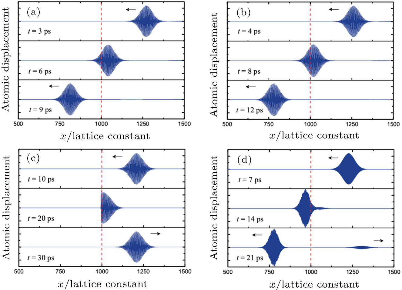 | Fig. 1. (color online) Snapshots of wave packets crossing the interface, red dashed lines denote the interface and the arrows indicate the travelling direction. (a) LA, frequency 16.8 THz. (b) TA, frequency 12.0 THz. (c) ZA, frequency 2.5 THz. (d) ZA, frequency 9.0 THz. Reprinted with permission from Ref. [50], copyright (2014) by the American Institute of Physics. |
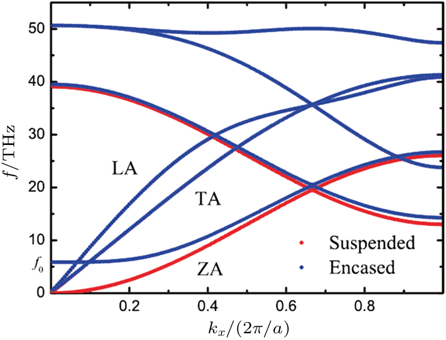 | Fig. 2. (color online) Phonon dispersions of suspended (red dots) and encased (blue dots) graphene. Reprinted with permission from Ref. [50], copyright (2014) by the American Institute of Physics. |
2.4. Quantum transport theories
where

is the transmission coefficient,

gives the energy of phonons, and

is the Bose–Einstein distribution of the left (right) regime. The transmission coefficient can be calculated starting from the scattering boundary theories, or by using the Greenʼs function technique. We need to emphasize that this formula evaluates the elastic transport, which means that the phonons do not lose or gain energy during travel. For the inelastic transport, NEGF still gives a formal expression to evaluate the thermal transport,[36] which is beyond the scope of Landauer picture.
In the nanoscale or low temperature regime, one needs to implement quantum distributions and evolutions to calculate the interfacial thermal transport properties. The difficulty is that one has to properly introduce the concept of temperature, a thermodynamic quantity, into the quantum dynamics. For this reason, a quantum heat bath is necessary in which the particles follow the Bose–Einstein distribution for Bosons and the Fermi–Dirac distribution for Fermions. The thermodynamics requires that the heat bath should have infinite degrees of freedom. It introduces difficulties to quantum mechanical treatment because the infinite limit needs to be properly taken care of.
A well-developed quantum theory to handle thermal transport is the non-equilibrium Green’s function (NEGF) formalism.[35] It is based on the quantization of the lattice dynamics and scattering theories. In the elastic regime, it recovers the Landauer formula. The Landauer formula gives a viewpoint that thermal transport is described as the transmission of heat carriers between two equilibrium baths. For phonons, it can be written as
 |
The NEGF formalism is based on a junction setup, where two (or more) heat baths are connected to a non-equilibrium center. The transmission coefficient measures the probability of a phonon transmitting from one heat bath to another through the center. Therefore, to evaluate the interfacial thermal transport, one needs to extend the interface and then regard it as a scattering center.[37,38] Normally it will increase the computational complexity. The formalism that directly calculates the interfacial thermal transport, where the heat baths are connected directly, has been developed,[39,40] and it is promising to apply to real materials.
Technological improvements based on NEGF formalism are continuously developing. For example, the implementation of inelastic scatterings, such as electron–phonon scattering [29,41] and phonon–phonon scattering,[42] has been developed. The modal analysis under the NEGF framework has also been formulated.[43] Integration of NEGF and MD has also been proposed to handle the complex structure of interface, where MD is used to simulate the atomic reconstruction and relaxation.[44] Beyond NEGF, other quantum theories based on the wave function picture have also been developed to handle the interface thermal transport.[45] It is proposed that the interfacial heat flux can be evaluated from the displacement fluctuations of the atoms at the interface.[46]
3. Various factors that affect ITC
3.1. Interfacial bonding
The strength of the bonding at the interface can directly affect the interfacial thermal conductance (ITC). In some interfaces, the bonding of the interface is very weak. For example, they are only connected through van der Waals interactions. AMM, also NEGF, predicts that in the weak bonding strength limit, ITC is proportional to the square of bonding strength.[38] However, in the moderate bonding strength regime, ITC can increase linearly with bonding strength. Furthermore, if the bonding is too strong, even stronger than the bonding inside the bulk material, then ITC may be suppressed with the increase of bonding strength.
Many NEMD studies imply that the formations of chemical bonds have significant influence on the ITC. The ITC between MoS2 and electrodes was studied,[47] where covalent bonds are formed. It was found that the covalent bonds serve as thermal channels for phonons to transmit over the interface. ITC becomes proportional to the density of bonds at the interface. Another study of ITC between silicon and a vertical carbon nanotube shows that the ITC can increase by two orders of magnitude if the chemical bonds are formed at the interface.[48] Similarly, MoS2–graphene in-plane interface was investigated by using NEMD. As shown in Fig. 
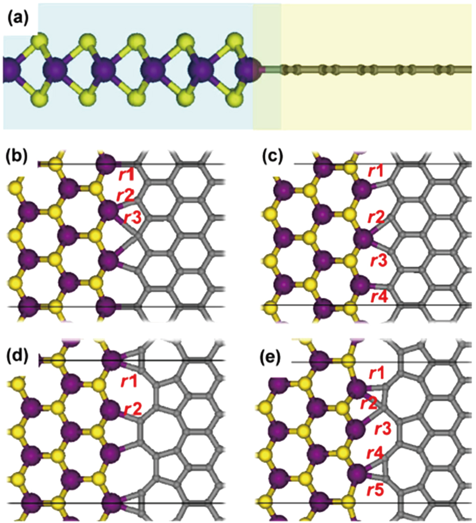 | Fig. 3. (color online) Interfaces of in-plane graphene–MoS2 heterostructures. Mo, S, and C atoms are shown in purple, yellow, and gray, respectively. Four possible interfacial configurations exist at the interface, as shown in panels (b)–(e). Reprinted with permission from Ref. [17], copyright (2017) by the Springer. |
The ITC can be controlled through the modulation of the density of interfacial chemical bonds. A study on silicon oxide-silicon (SiO2–Si) interface reveals that the interfacial bond strength can affect its sensitivity to the atomic structures.[49] For weak bonds, the ITC is very sensitive to the atomic structure of the interface, while in the strong bonds regime, it becomes insensitive to the detailed structures. Other systems, such as interface between suspended and encased graphene,[50] self-assembled SAM–SI interface,[51] and metal–insulator interface, also show a strong bond-strength dependence of ITC. In addition to the bond strength, an NEGF study of graphene/hexagonal boron nitride (h-BN) interface shows that the type of bonds can also affect the thermal transmission.[43] The carbon–nitrogen bonds in the zigzag direction transmit high-frequency phonons more efficiently than the carbon–boron bonds.
Atomic defects, such as atomic vacancies, are always present in materials. The vacancies disrupt lattice structures and cause additional scattering to phonon transport. Similarly, atomic vacancies at the interface will also affect the ITC remarkably. As shown in Fig.
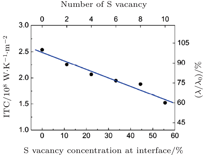 | Fig. 4. (color online) Interfacial thermal conductance as a function of S vacancy concentration at the interface. Reprinted with permission from Ref. [47], copyright (2016) by Springer. |
3.2. Defects and surface roughness
Interfaces are the places where defects can be easily introduced due to the mismatch of the lattices, the release of the stress, and the contamination during the formation of the interfaces. Then one would ask what is the effect of defects on the ITC. Usually defects will introduce imperfection to the lattice structure, increase the surface roughness, cause additional scatterings to the phonons, and then reduce the ITC. While high-frequency phonons can be scattered by the lattice mismatch, the defects are able to scatter low-frequency phonons and hence reduce the ITC.[44] However, a recent study on the graphene/h-BN interface found an abnormal behavior that defects are able to enhance the ITC.[52] As shown in Fig. 

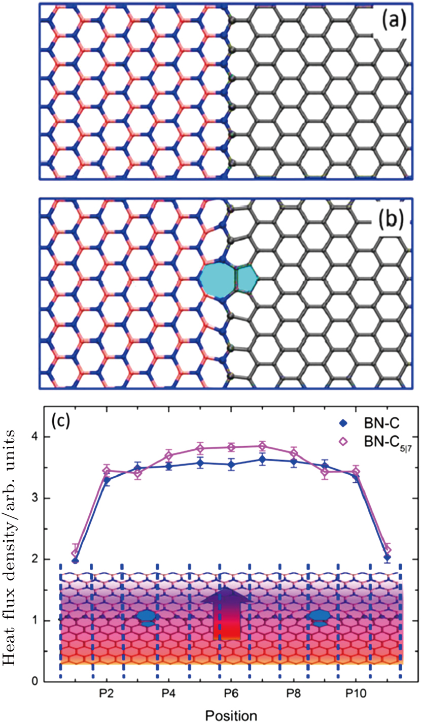 | Fig. 5. (color online) Heterostructure with different interfaces between graphene and h-BN. (a) N–C connected interface, BN–C; (b) N–C connected interface with 


|
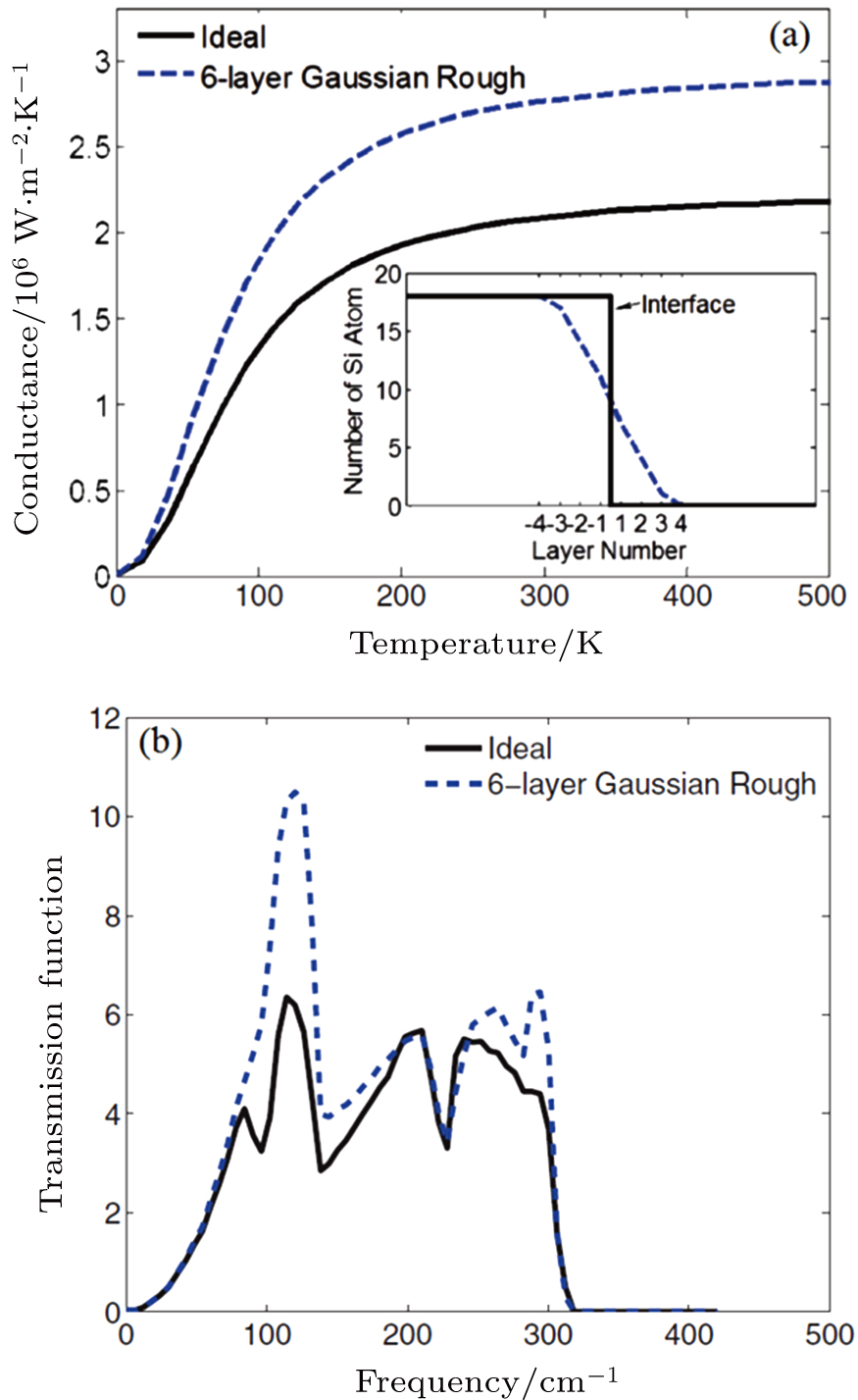
Interface roughness is another important factor influencing the ITC. Experimentally, the interface roughness can be controlled by the growth condition and formation process. Generally, the interface roughness has similar effects as the defects, which causes scatterings and localization of phonons, especially for high-frequency phonons.[15,53] However, the enhancement of phonon transmission by surface roughness has been reported at a Si–Ge interface.[54] As shown in Fig.
 | Fig. 6. (color online) (a) Thermal conductance as a function of temperature for an ideal Si/Ge interface (solid black line) and for a rough Si/Ge interface with a Gaussian distribution (dashed blue lines). (b) Total transmission function for an ideal Si/Ge interface and for a rough Si/Ge interface. Reprinted with permission from Ref. [54], copyright (2012) by the American Physical Society. |
3.3. External forces
We first look at the effects of the applied strain on ITC. Strain is a commonly used method to modulate the interatomic force constants and hence change the thermal transport properties.[43,55–57] Using graphene junctions with different mass distributions as an example, Pei et al. studied the effect of strain on interfacial thermal resistance. Strong phonon scattering at the interface results in a sharp temperature jump in the temperature profile. As shown in Fig.
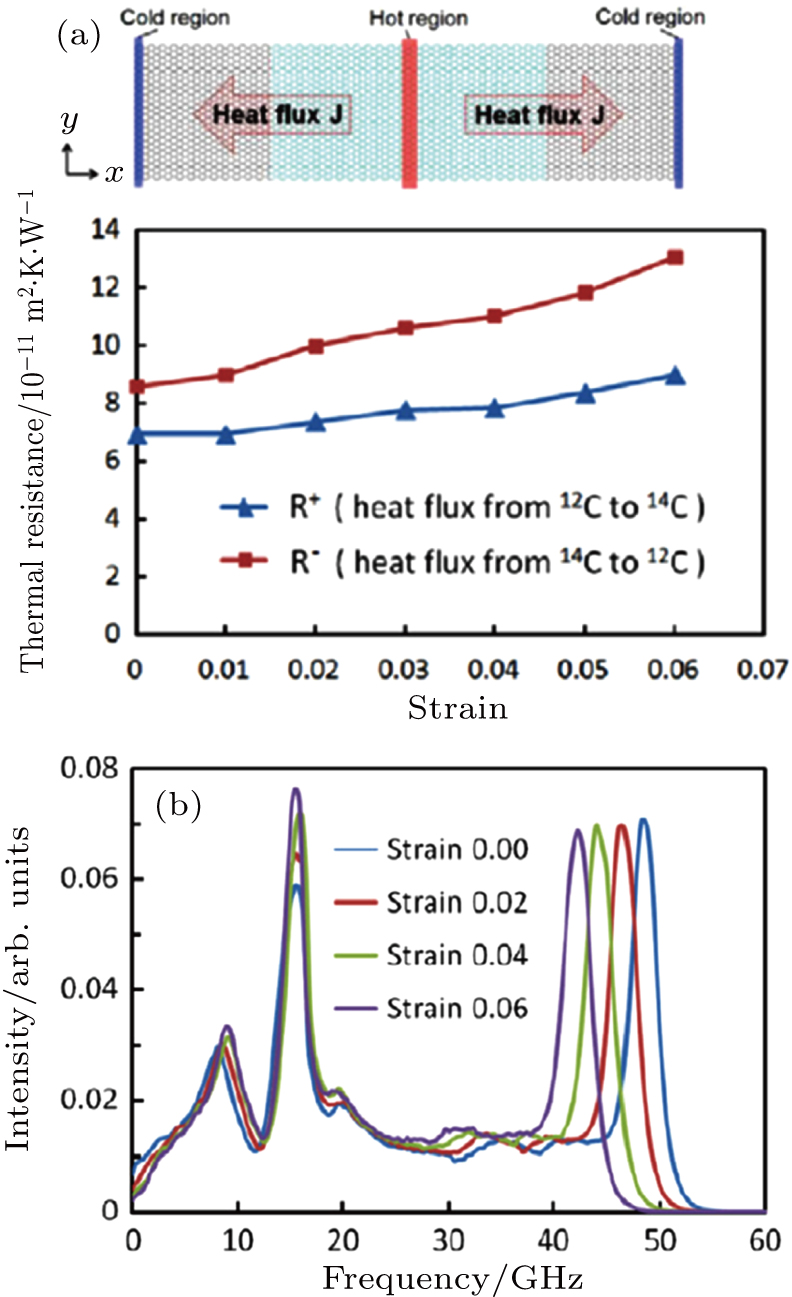 | Fig. 7. (color online) (a) The effect of tensile strain on the interfacial thermal resistance. The interface between pristine and isotope-doped graphene is also shown here. (b) Phonon spectra of atoms near the interface under different tensile strains. Reprinted with permission from Ref. [56], copyright (2012) by the American Institute of Physics. |
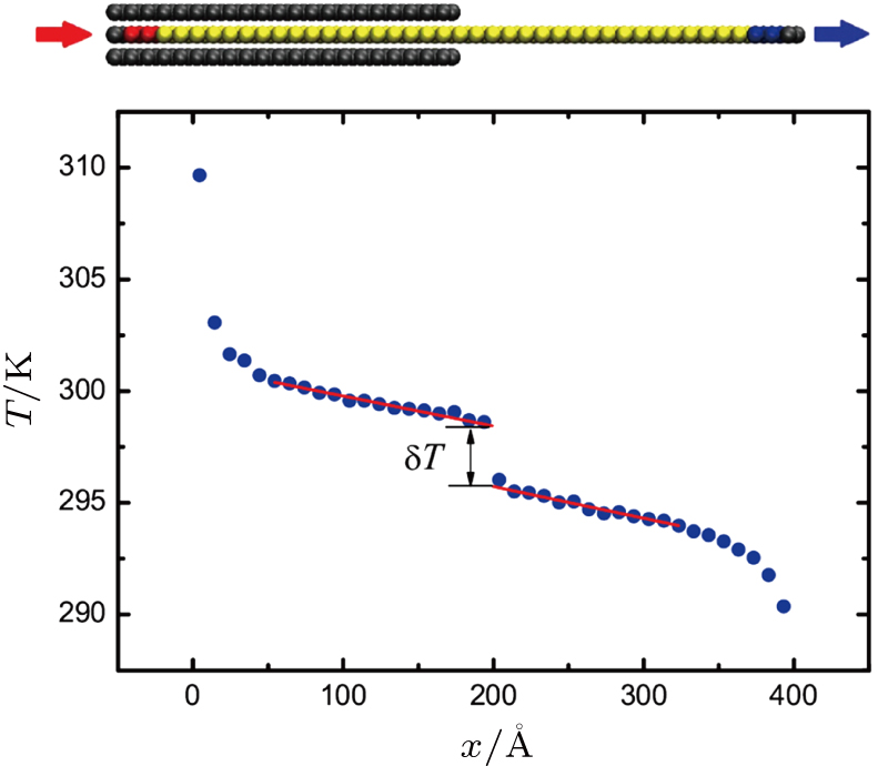
Another kind of external force is the van der Waals interaction, through the substrates or other coating materials for two-dimensional materials. These interactions provide onsite potentials to the atoms in the material and hence greatly affect their out-of-plane vibration. Taking graphene as an example, the flexural modes (ZA modes) are the major heat carrier in suspended graphene and they are significantly suppressed once the graphene is encased. Interestingly, even for one graphene sheet, if half section is supported and the other half is suspended, there still exists interfacial thermal resistance inside the graphene sheet.[50] The system structure is shown in Fig. 
 | Fig. 8. (color online) Side view of the simulating model, and a typical temperature profile at steady state. Here the black colored atoms are fixed, red and blue colored ones contact with heat source and sink in non-equilibrium MD simulations, respectively. Reprinted with permission from Ref. [50], copyright (2014) by the American Institute of Physics. |
The phenomenon demonstrated in the encased and suspended graphene junction closely relates to graphene’s two-dimensional topology, so that the weak graphene–substrate interaction can directly influence its thermo-mechanical property. It is worth emphasizing that using this effect, graphene-based thermal modulators have been proposed. The clamp-graphene distance, controlled by an external pressure, is able to modulate the thermal transport of grapheme.[16] In boron nanoribbons, it is found that the van der Waals interactions cause the enhancement of thermal conduction.[59] It is suggested that inelastic scatterings take the responsibility.
3.4. Atomic species and mass ratio
The atomic species of the interface can significantly affect the ITC. For example, the graphene–MoS2 has much lower ITC than the graphene/graphene or MoS2/MoS2 interface.[57] It is also reported that the carbon atoms in the graphene/h-BN interface reduce the ITC.[60] In other cases, even the species of the atoms are the same, the ITC can be affected by introducing isotope atoms.[56] The difference in atomic mass causes phonon scatterings and then reduces the thermal transport. Hence it has been proposed that interfacial thermal transport between two dissimilar materials can be tuned by modulating their relative mass ratio.[61] As the atomic species at the interface can efficiently affect the ITC, an interesting idea is to use molecular cross-linker to modulate thermal transport. It has been found that a cross-linker between two graphene nanoribbons can effectively transmit out-of-plane modes and it filters the in-plane modes.[62]
3.5. Lattice orientations
ITC is often closely related to the lattice orientations, even when the materials themselves are isotropic. In the graphene/h-BN interface, it is found that zigzag interfaces cause stronger reduction of ITC due to the enhanced phonon localization. The interfacial structure can also affect the orientation of the transmitted phonons.[43] Besides the alignment of interfacial structure, the incident angle of phonons is also important to determine whether they are transmitted or reflected. A simulation of Si/Ge interface shows that the phonon transmission changes smoothly by varying the incident angle, and a critical angle exists.[63]
3.6. Size effects
Due to a contribution from acoustic modes that possess long wavelength, size will also affect the interfacial thermal conductance.[64] In the study of interfaces formed by suspended and encased graphene, it is found that the ITC will increase with the increase of the system length, and then gradually saturates.[50] Similar results are observed from the interfaces formed due to grain boundaries of graphene, where a decrease in size will significantly suppress the ITC.[65] It has also been suggested that the size effect is more significant in weakly coupled interfaces, but less important in strongly coupled interfaces.[49]
3.7. The role of inelastic scattering
Inelastic scattering means that the energy of phonon changes during the scattering. For example, in the three-phonon process, an incident phonon can split into two phonons, or two phonons can be combined into a single one. If inelastic scattering happens, then the energy can transfer from the low-frequency phonons at one side of the interface to high-frequency phonons at the other side.[66]
Normally inelastic scatterings suppress the ITC because they introduce additional scatterings to the phonons, and hence reduce the mean free path of the phonons. Inelastic scatterings thermalize the phonons and cause them to obey the Bose–Einstein distribution in equilibrium condition. However, experiments on metal–diamond interfaces show that the ITC is extremely high,[67,68] 100 times larger than the calculation of lattice dynamics. It suggests that inelastic scattering plays an important role to provide extra channels for heat transport, due to either the electron–phonon interaction or the phonon–phonon interaction. Inelastic scattering even dominates the interfacial thermal transport when the phonon spectra of the two sides of the interfaces are highly dissimilar.[69]
Starting from different theoretical frames, several results suggest that inelastic scattering is possible to enhance the ITC.[31,70–72] The inelastic scattering provides extra channels for phonons to transport across the interface.[70] It also thermalizes the phonons, which possibly increases the population of modes with high transmission coefficients.[71] Another study reveals that the nonlinear coupling at the interface can enhance the ITC if the linear coupling is weak. In contrast, if the linear coupling is strong, it will suppress the ITC, instead of increasing the ITC.[72]
4. Applications of ITC
4.1. Thermal rectification
where


is the forward (backward) heat flux under the same small temperature bias. Numerical simulations suggest that thermal rectification can be realized in many interfacial systems, such as graphene–silicon junction,[55] interfaces between suspended and encased grapheme,[50] silicon–amorphous polyethylene interface,[73] metal–insulator interface via electron–phonon interaction,[74] carbon isotope doping induced interface,[56] two-dimensional Ising lattice,[75] and one-dimensional anharmonic atomic chains.[37,76] The rectification ratio can be up to 40%–50% in material simulations.[50,73] In a one-dimensional model, it has been shown that the rectification results from the biased transmission properties of the high-frequency phonons. Hence, a thermal rectifier can be constructed by filtering the high-frequency phonons in one direction.
An important consequence of inelastic scattering is the thermal rectification,[24,37] which plays the key role in the application of thermal diode[22] and phononics.[23] Thermal rectification is the effect that the thermal conductance differs between forward and backward flows of heat. Interface scatterings can be used to realize such effects.[24] The significance of such effects is characterized by the thermal rectification ratio
 |
4.2. Thermal interface materials
In the nano-electronic devices, heat is unavoidably produced. Fast dissipation of heat is one of the major issues that affect the performance and its maximum sustainable power. In the heat dissipation process, the interfacial thermal resistance is a challenge. The research of interfacial thermal materials aims to find materials that can be inserted into the devices and heat sink, in order to suppress the interfacial thermal resistance and enhance heat dissipation. Some low-dimensional materials, such as graphene, show promising potentials in the applications of heat removal. A comprehensive understanding of the mechanisms that govern the interfacial thermal resistance can direct the design of thermal interface materials.
5. Summary and outlook
In the continuous scaling down of nano-devices, the management of interfacial thermal properties becomes more important now. The goal is that the heat flux across the interface can be effectively controlled, and thus the heat generated in the nano-devices is well managed. To achieve this, a deep and clear understanding of the transport mechanism at the interface is required. The theories of interfacial thermal transport have been continuously progressing, from the acoustic/diffusive mismatch model to the atomic-level modern simulation tools. The advances of theory and simulation power allow deeper understanding of the underlying interfacial transport mechanism, together with the emergence of new research areas such as phononics.[23]
Despite plentiful progress, the interfacial thermal transport properties are still not fully understood, especially in the inelastic scattering regime. Molecular dynamics simulation can consider the anharmonic impacts; however, it is difficult to integrate the quantum effects. The inelastic quantum scattering at the interface is a challenge to capture. The quantum theories, such as NEGF, only allow perturbation treatment for the inelastic scattering, which will break down in the strong nonlinear regime. The quantum master equation formalism allows exact treatment of the inelastic scattering,[77,78] but the computational complexity limits its application to small systems with few degrees of freedom. Hence a comprehensive theory which fully describes the transport mechanism at the interface is still lacking. Such theory may enrich the physics of interfacial thermal transport properties and probably reveal new transport mechanisms.
Another important aspect of interfacial thermal transport lies in the metal–insulator interface, where the electron–phonon interaction plays an important role. In the metal-insulator interface, besides the channel of lattice vibration, the thermal energy of metal can be transmitted through electron–phonon interaction. The electron–phonon interaction can take place in two different ways. The first one is that electrons in metal first interact with the phonons in metal and then transmit the energy though lattice vibration at the interface. The other way is the direct interaction between the electrons in metal and the phonons in insulator. The electron–phonon interfacial conductance has been found to be substantially important.[18,29,74,79,80] The heat flow can be mediated through the surface state of the electrons.[81] However, the simulation of electron–phonon interfacial thermal conductance is challenging due to its nonlinear nature and the strong quantum effects of electrons. A two-temperatures Boltzmann transport equation approach has been developed for such problem based on the diffusive transport assumption, in combination with molecular dynamics simulation.[82,83] In the weak electron–phonon interaction regime, NEGF provides a way to handle the transport problem in the junction setup.[41] However, a complete quantum mechanical description of electron–phonon interfacial problem is lacking, and also promising.
Reference
| [1] | |
| [2] | |
| [3] | |
| [4] | |
| [5] | |
| [6] | |
| [7] | |
| [8] | |
| [9] | |
| [10] | |
| [11] | |
| [12] | |
| [13] | |
| [14] | |
| [15] | |
| [16] | |
| [17] | |
| [18] | |
| [19] | |
| [20] | |
| [21] | |
| [22] | |
| [23] | |
| [24] | |
| [25] | |
| [26] | |
| [27] | |
| [28] | |
| [29] | |
| [30] | |
| [31] | |
| [32] | |
| [33] | |
| [34] | |
| [35] | |
| [36] | |
| [37] | |
| [38] | |
| [39] | |
| [40] | |
| [41] | |
| [42] | |
| [43] | |
| [44] | |
| [45] | |
| [46] | |
| [47] | |
| [48] | |
| [49] | |
| [50] | |
| [51] | |
| [52] | |
| [53] | |
| [54] | |
| [55] | |
| [56] | |
| [57] | |
| [58] | |
| [59] | |
| [60] | |
| [61] | |
| [62] | |
| [63] | |
| [64] | |
| [65] | |
| [66] | |
| [67] | |
| [68] | |
| [69] | |
| [70] | |
| [71] | |
| [72] | |
| [73] | |
| [74] | |
| [75] | |
| [76] | |
| [77] | |
| [78] | |
| [79] | |
| [80] | |
| [81] | |
| [82] | |
| [83] | |
| [84] |