Fabrication and characterization of ultra-low noise narrow and wide band Josephson parametric amplifiers
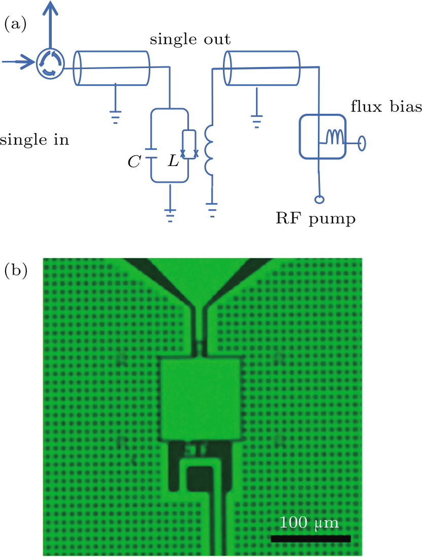
(color online) (a) A schematic diagram of our parameter amplifier. The circle represents the circulator in the measuring circuit. The circulator is used to separate the input signal and output signal. The cylinder represents 50 Ω signal input transmission line and on chip flux bias line. The square represents bias T to combine the RF pump and DC bias. (b) The optical micrograph of our Josephson parameter amplifier. The up triangle pad is the signal input pad, the center square is the parallel plate capacitor, and the down turning line is the on chip bias line.