

Highly conductive and transparent carbon nanotube-based electrodes for ultrathin and stretchable organic solar cells
Cite this Article
Fan Qingxia, Zhang Qiang, Zhou Wenbin, Yang Feng, Zhang Nan, Xiao Shiqi, Gu Xiaogang, Xiao Zhuojian, Chen Huiliang, Wang Yanchun, Liu Huaping, Zhou Weiya. Highly conductive and transparent carbon nanotube-based electrodes for ultrathin and stretchable organic solar cells. Chinese Physics B, 2017, 26(2): 028801 
Permissions
Highly conductive and transparent carbon nanotube-based electrodes for ultrathin and stretchable organic solar cells
† Corresponding author. E-mail:
Abstract
In this work, we have presented a freestanding and flexible CNT-based film with sheet resistance of 60 Ω/□ and transmittance of 82% treated by nitric acid and chloroauric acid in sequence. Based on modified CNT film as a transparent electrode, we have demonstrated an ultrathin, flexible organic solar cell (OSC) fabricated on 2.5-μm PET substrate. The efficiency of OSC, combined with a composite film of poly (3-hexylthiophene) (P3HT) and phenyl-C61 butyric acid methyl ester (PCBM) as an active layer and with a thin layer of methanol soluble biuret inserted between the photoactive layer and the cathode, can be up to 2.74% which is approximate to that of the reference solar cell fabricated with ITO-coated glass (2.93%). Incorporating the as-fabricated ITO-free OSC with pre-stretched elastomer, 50% compressive deformation can apply to the solar cells. The results show that the as-prepared CNT-based hybrid film with outstanding electrical and optical properties could serve as a promising transparent electrode for low cost, flexible and stretchable OSCs, which will broaden the applications of OSC and generate more solar power than it now does.
1. Introduction
Organic solar cells (OSCs), with their unique characteristics such as mechanical compliance, light weight, low-cost manufacturing, convenience of integration and compatibility with roll-to-roll mass production, have drawn a great deal of attention.[1,2] The relatively inferior performance of the OSCs compared to the inorganic solar cells could be compensated by the features that inorganic solar cells do not possess, such as, much thinner devices because of strong absorption of the organic semiconductors, undemanding purity and solution process of the organic semiconductors.[3] The properties of the OSCs mentioned above make them suitable to conformally integrate with buildings or epidermis that have irregular surfaces. A major obstacle in developing flexible OSC is the use of a brittle and expensive traditional transparent electrode, indium tin oxide (ITO). Carbon nanotube (CNT) films can serve as an alternative due to their superior conductivity and high transparency in visible and infrared spectral range. Opposite to ITO, CNT films possess inherent flexibility, an abundance of raw materials, compliance with solution processing, low haze and reflection.[4] CNT films have been successfully used as transparent conductive electrode in OSCs, some have achieved comparable performance with the OSCs using ITO as photo anodes.[5–9] Based on ultrasmooth and large-area CNT films with 180 Ω/□ sheet resistance and ∼ 78% transparency produced by ultrasonic spraying method, OSCs fabricated on CNT film or ITO electrodes demonstrated a high power conversion efficiency (PCE) of ∼ 3.1% and 3.6%, respectively.[10] Only flexible OSCs were obtained in previous reports, in which OSCs using CNT as transparent electrode were built on flexible substrate. Simple flexibility, however, cannot satisfy most applications that need stretchability or compressibility, such as integrated with moving parts of the machine or body. Combining stretchability not just flexibility to OSC would broaden the applications and generate more solar power than it now does. To our knowledge, there have not been any reports about using CNT-based film as a transparent electrode in stretchable OSC devices.
At the present stage, sheet resistance (R □) of CNT film at high transmittance is relatively large in comparison with that of ITO. A variety of post-treatment approaches have been carried out on enhancing the conductivity of CNT films, for example, involving acids,[11,12] metal chlorides,[13,14] alkali metals,[15] boron and nitrogen atoms,[16] or combination of the above-mentioned methods.[17] Among the aforementioned methods, acid treatment is most commonly used by immersing CNT film into acids. Treating CNT film with metal chlorides is another valid post-treatment method. Gold chloride acts as a representative dopant, which could impressively enhance the conductivity while keeping the initial transmittance. Moreover, CNT films treated with gold ion is expected to be simple, fast, and environmentally friendly. In most previous research, CNT transparent electrodes are made by vacuum filtration, spray coating or printing stabilized CNT dispersion solutions, but these methods suffer from fussy procedures, agglomeration of the CNTs, damage to CNTs induced by ultraphonic, and so on. CNT films fabricated by a chemical vapor deposition (CVD) are robust, freestanding, easily scale up, convenient for post-treatment, and can be transferred to a variety of substrates, which is suitable for a transparent anode in OSC.
In this work, firstly we have presented a freestanding and flexible CNT film, which was treated with nitric acid and chloroauric acid in sequence, yielding a quite low sheet resistance of 60 Ω/□ at 82% transmittance. Furthermore, we demonstrated ultrathin, flexible organic solar cells based on chloroauric acid modified CNT (Au-CNT) films as transparent electrodes, which were fabricated on 2.5-μm PET substrate. The efficiency of OSC with poly (3-hexylthiophene) (P3HT) and phenyl-C61 butyric acid methyl ester (PCBM) composites as active layer can be up to 2.74%, which is approximate to that of the reference solar cell fabricated with ITO-coated glass (2.93%). As the mechanical compliance of the thin film solar cell is imparted by substrate predominantly, incorporating the as-fabricated OSC with pre-stretched elastomer, 50% compressive deformation can apply to the solar cells.
2. Experimental section
2.1. Preparation of the CNT-based transparent electrode
The large area and freestanding CNT films with high transmittance and low sheet resistance were prepared by a developed chemical vapor deposition method. More details can be found in our previous reports.[18] The transmittance and thickness of the as-synthesized CNT film could be controlled by adjusting the growth parameters, such as growth time and carbon feedstock, etc. The freestanding CNT network fixed on a frame with a square hole was immersed in nitric acid (65 wt%) for 5 hours to remove the residual catalysts and improve the conductivity; the CNT film was rinsed with deionized water repeatedly before use.
A 2.5-μm thick PET (Mylar Polyester CAT NO: 106) was stuck on a rigid glass slide to provide a smooth surface for fabricating OSC devices conveniently. The CNT film fixed on a frame was placed on the as-prepared substrate. A drop of ethanol to the top of the CNT film is indispensable to ensure a tight contact between the CNT film and PET when the ethanol is volatilized.
For the Au-CNT film, solutions of HAuCl4·4H2O in ethanol at the concentrations of 2, 5, 10, 20, 30, 40, 50 mM were spin coated on CNT film at 2000 rpm followed by annealing at 120 °C for 15 min.
2.2. Device fabrication
For the reference OSC devices, ITO-coated glass substrate with a sheet resistance of 15 Ω/□ was cleaned sequentially in isopropanol, acetone, ethanol and water for 10 min each and then dried in a stream of nitrogen gas. The ITO-coated glass substrate was treated with oxygen plasma (140 W, 5 min) before the next step.
A layer of PEDOT:PSS (Clevios PH 1000, purchased from Heraeus, mixed with 5-vol% dimethylsulfoxide (DMSO) and 1-vol% Zonyl FS-300 fluorosurfactant, obtained from Alfa Aesar) was spin coated on the CNT film or ITO-coated substrate at 4000 rpm for 120 s. The samples were annealing at 120 °C for 15 min in the air, a 90-nm-thick PEDOT:PSS was obtained.
Subsequently, the photoactive layer was then deposited by spin coating a blend solution of 30-mg/mL P3HT (1-materials) and 24-mg/mL PCBM (obtained from Solenne b.v.) dissolved in ortho-dichlorobenzene (o-DCB). The spin speed was 1500 rpm for the ITO reference OSC devices and 850 rpm for those using CNT film electrodes, which is because devices with CNT film electrodes had a larger accidental shorting probability due to the protruding CNTs. The devices were transferred to an argon-filled glove box and allowed solvent annealing treatment for 20 min. Biuret dissolved in methanol (1 mg/mL) was directly spin coated on P3HT:PCBM at 3000 rpm for 30 s, which served as cathode buffer layer, if needed. Then, the samples were annealed at 140 °C for 20 min.
Finally, a drop of Eutectic Gallium-Indium (EGaIn, obtained from Alfa Aesar) was applied to the surface of P3HT:PCBM, which served as cathode. A copper wire was attached to the EGaIn in order to test conveniently. The area of the device is calculated by the contact area between the EGaIn and the photoactive layer and measured using optical microscope, which is typically about 3 mm2 to 7 mm2. EGaIn also can be recyclable by using a syringe. While completed OSC devices cannot use EGaIn as cathode, its use is quite convenient in laboratory to evaluate the performance of the photovoltaic devices.
2.3. Characterization and measurements
The optical transmittance and absorption spectra of CNT film and Au-CNT film were measured utilizing a UV-Vis-NIR spectrophotometer (UV-3600, Shimadzu). Sheet resistances of the films were measured by Keithley 2400 with a four-electrode method. The morphology of the CNT film and Au-CNT film and OSC devices was characterized by a scanning electron microscope (SEM, Hitachi S-5200) and atomic force microscope (AFM, Bruker MultiMode-8 ScanAsyst). The performances of the solar cells were carried out using a solar simulator (CHF-XM 500, Beijing Trusttech Co. Ltd.) under AM 1.5 G with a calibrated irradiation intensity of 100 mW/cm2. The J–V data were collected using a Keithley 4200-SCS, and all the tests were performed in air. We determined the thickness of the films from the Bruker Dektak XT stylus profiler.
2.4. Compressing and stretching
Tensile strain was loaded and unloaded using a laboratory-made stretching stage equipped with a stepper motor and controlled by computer. The stage consisted of an actuating unit (moving part) and a stationary part. We placed an elastomer (3M VHB 4905) between the two clamps and stretched it by moving the clamps further apart. The whole OSC device using CNT-based transparent electrode can be peeled off from the rigid glass slide. The sample was adhered onto the elastomer followed by compressing, and then the irregular wrinkles and buckled structure were formed. We defined the length between the moving part and stationary part of the stretching stage as L, and when OSC device was in flattened status as L 0. The compressive strain was calculated to be (L 0 − L)/L 0. As for the tensile strain (elongation), we used the shortest status as the starting point where the compressive strain is 50%, so when the OSC devices were re-stretched to the flattened status, the tensile strain could reach 100%.
As for the resistances of the CNT film and CNT/PEDOT:PSS composite film under cyclic compressing and stretching, each of them on 2.5-μm PET substrate were attached onto the elastomer. Silver paste was painted at the ends of the films acting as electrodes, the resistance was measured using a Keithley 2400 multimeter through a two-electrode method. The whole system was controlled by a computer through a LabVIEW program.
3. Results and discussion
where σDC is the DC conductivity, σopt is the optical conductivity of the films, Z
0 ≈ 376.73 Ω is the impedance of free space, T is the transmittance of the films.
Large scale, freestanding, robust and continuous CNT network films were directly produced using a developed CVD technology by our group previously. The photograph in Fig.
 | (1) |
 | Fig. 1. (color online) Photograph of (a) a freestanding CNT film fixed on polymethyl methacrylate frame with a hole (6 cm×5 cm). (b) The sheet resistance and transmittance of Au-CNT film as a function the concentration of chloroauric acid. |
Taking both R □ and T into consideration, the best FOM value of 28.9 appears at 5-mM chloroauric acid treated CNT film. The reduction ratio of the R □ reaches 35% with the R □of 60 Ω/□, at the same time, the transmittance drops slightly from 85% to 82%. The CNT film treated with nitric acid and chloroauric acid in sequence exhibits a three-fold smaller R □, which drops from 182 Ω/□ to 60 Ω/□. Our method provides an effective strategy to improve the conductivity of the CNT film impressively.
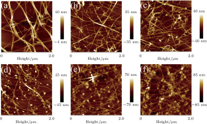
AFM images in Fig.
 | Fig. 2. (color online) The AFM images of the CNT film treated with (a) 0-mM, (b) 2-mM, (c) 5-mM, (d) 10-mM, (e) 30-mM, and (f) 50-mM chloroauric acid. |
In order to demonstrate the suitability of our CNT films for application in transparent electrode, we fabricated OSCs using P3HT and PCBM as bulk heterojunction (BHJ). The OSC devices have been constructed using CNT films coated on a 2.5-μm PET substrate and ITO-coated glass substrates as transparent electrode, which were fabricated side-by-side for comparison. The structure of the OSC device is shown in Fig.
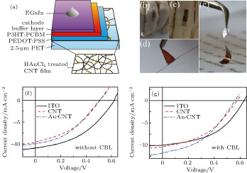 | Fig. 3. (color online) (a) Schematic diagram of OSC structure with Au-CNT film as anode. Photographs of flexible OSC mounted on a finger when the finger was (b) bent and (c) straight. (d) Photograph of OSC wrapped around a copper wire, whose diameter is 200 μm. (e) Photograph of ultrathin flexible OSC. J–V characteristics of OSC constructed on CNT, Au-CNT, and ITO electrode (f) without and (g) with the cathode buffer layer, under illumination of a simulated AM 1.5 G 100-mW/cm2 light. |
Figure
| Table 1.
Device characteristics of anode/PEDOT:PSS/P3HT:PCBM/CBL/EGaIn solar cells fabricated using ITO, CNT, and Au-CNT electrodes. . |
The efficiency of BHJ OSC depends not only on the morphology of the photoactive layer, but also the properties of the interfacial layers. Optimizing the interface layers between the photoactive layer and the electrodes plays a key role in promoting carrier selectivity, reducing interfacial recombination and improving carrier separation and collection.[26–29] At the interface between anode and photoactive layer, PEDOT:PSS, graphene oxide (GO) or transition metal oxides, such as, V2O5 and MoO3 are commonly used as anode buffer layer (ABL).[30,31] Meanwhile, there is an energy level offset about 0.2 eV between the work function of the EGaIn (4.2 eV) and lowest unoccupied molecular level (LUMO) of the PCBM (4.0 eV),[32–34] which could block the electron extraction and transportation, resulting in a lower FF and PCE. So, it is quite important to incorporate a suitable cathode buffer layer that could modify the energy level offset between the photoactive layer and cathode. Thermally evaporated low work function metal Ca, Ba and alkali metal compounds LiF are widely applied as cathode buffer layer, which, however, suffer from poor stability and are incompatible with large area and vacuum-free deposition.[22,35] Alcohol or water soluble conjugated polymers or small molecules have attracted considerable attention as cathode buffer layer because of facility and solution processing,[26,27,32,34] small molecules have more advantages over conjugated polymers, such as, easy synthesis, certain molecular weight and structure. With the purpose of enhancing the performance of organic solar cells devices, we incorporated biuret (containing two amino (–NH2) groups) dissolved in methanol as cathode buffer layer. Detailed results are summarized in Fig.
Incorporation of the biuret as the cathode buffer layer brings an improvement for all of the three organic solar cell devices fabricated using indium tin oxide, carbon nanotube, and Au-carbon nanotube as electrodes, as shown in Fig.
With growing interest in flexible electronics, we finally demonstrated a demo of our device to realize flexibility and stretchability. The mechanical properties of thin film solar cell crucially depend on the substrate, flexible application of our OSC devices have been accomplished by constructing them on an ultrathin (2.5 μm) PET substrate and using CNT film as transparent electrode, whose total thickness is less than 3.5 μm. By combining mechanical compliance CNT film and flexible substrate together, the OSC devices exhibit extreme flexibility, and could not only be easily wrapped around and attached to a moving part through a double faced adhesive tape as shown in Figs.
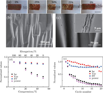
By adhering the OSC device built on ultrathin PET substrate to a pre-stretched elastomer, irregular wrinkles and buckled structure are formed under release of the pre-stretched elastomer [Figs.
 | Fig. 4. (color online) (a) Photographs of the solar cell attached on a pre-strained elastomer under various compressive deformations, the scale bar is 5 mm. (b) and (c) SEM images of solar cell under 50% compressive strain. Inset in panel (c) is the SEM image of solar cell after cyclic test. (d) Normalized photovoltaic characteristics of OSC under various compressive states and (e) under cyclic compressing and stretching with a compressive deformation of 50%. Photovoltaic characteristics tests of OSC were performed under fully extended state at each cycle. |
In order to find possible reasons for the performance degradation of the OSC devices, we investigated the resistance of the CNT-based electrode and the morphology of the devices before and after the cyclic test. The changes in electrical resistance of the CNT film and CNT/PEDOT:PSS composite film with various compressive levels and 1000 cycles of compressing and stretching from 0% to 50% compressive deformation were measured in-situ by a resistance measurement compressive test system. The increscent resistances of the CNT film (7.7%) and CNT/PEDOT:PSS composite film (9.5%) during compressing also contribute a little to the decrease of the I
sc and FF. After 1000 cycles of compressing and stretching from 0% to 50%, the resistances of both CNT film and CNT/PEDOT:PSS composite film show 51% and 57% increment, which can decrease the I
sc to a certain extent. There is no marked damage on the CNT and CNT/PEDOT:PSS composite film after the cyclic mechanical test. However, cyclic tests introduce irreversible damage to the OSC devices, cracks begin to appear in the active layer where the curvature is large, which are perpendicular to the compressing direction (inset in Fig.
4. Conclusion
In summary, we have prepared a highly conductive, transparent and flexible CNT-based electrode, which exhibits a sheet resistance of 60 Ω/□ and a transmittance of 82% by treating with nitric acid and 5-mM chloroauric acid in sequence. In addition, mechanical tests showed that the CNT film and CNT/PEDOT:PSS composite film were able to with-stand large mechanical deformation. Bulk heterojunction OSC devices based on a blend of P3HT:PCBM were fabricated on 2.5-μm PET substrates. Using CNT-based electrodes, a thin layer of methanol soluble biuret inserted between the photoactive layer and the cathode as CBL, the PCE of as-fabricated OSC has achieved 2.74%, which is comparable to that obtained using conventional ITO anode. By attaching the devices to a pre-stretched elastomer, the OSC could bear 50% compressive strain. The degradation of the ITO-free OSC is mainly caused by the cracks in the photoactive layer, and two corresponding ways to avoid or reduce the crack have been put forward preliminarily. It can be concluded that CNT-based hybrid film with outstanding electrical and optical properties could serve as a promising replacement of commonly used ITO for low cost, flexible and stretchable organic solar cells, which will broaden the applications of OSC and generate more solar power than it now does.
Reference
| [1] | |
| [2] | |
| [3] | |
| [4] | |
| [5] | |
| [6] | |
| [7] | |
| [8] | |
| [9] | |
| [10] | |
| [11] | |
| [12] | |
| [13] | |
| [14] | |
| [15] | |
| [16] | |
| [17] | |
| [18] | |
| [19] | |
| [20] | |
| [21] | |
| [22] | |
| [23] | |
| [24] | |
| [25] | |
| [26] | |
| [27] | |
| [28] | |
| [29] | |
| [30] | |
| [31] | |
| [32] | |
| [33] | |
| [34] | |
| [35] | |
| [36] | |
| [37] | |
| [38] |