


High pressure x-ray diffraction techniques with synchrotron radiation
[Liu Jing†,  ]
]
]
|
|


† Corresponding author. E-mail:
Project supported by the National Natural Science Foundation of China (Grant Nos. 10875142, 11079040, and 11075175). The 4W2 beamline of BSRF was supported by the Chinese Academy of Sciences (Grant Nos. KJCX2-SW-N20, KJCX2-SW-N03, and SYGNS04).
This article summarizes the developments of experimental techniques for high pressure x-ray diffraction (XRD) in diamond anvil cells (DACs) using synchrotron radiation. Basic principles and experimental methods for various diffraction geometry are described, including powder diffraction, single crystal diffraction, radial diffraction, as well as coupling with laser heating system. Resolution in d-spacing of different diffraction modes is discussed. More recent progress, such as extended application of single crystal diffraction for measurements of multigrain and electron density distribution, time-resolved diffraction with dynamic DAC and development of modulated heating techniques are briefly introduced. The current status of the high pressure beamline at BSRF (Beijing Synchrotron Radiation Facility) and some results are also presented.
Since the late 1970s, high-pressure (HP) synchrotron research has become a fast growing field. Over the past few decades, various HP experimental techniques based on synchrotron radiation have been successively developed, including HP x-ray diffraction (XRD), HP x-ray spectroscopy (XRS), HP inelastic x-ray scattering (IXS), HP x-ray imaging, etc. In these techniques, XRD is the most common technique for high-pressure investigations and has been widely used for in situ determination of the structure and properties of materials.
Combining pressure vessels, like diamond anvil cells or large volume press, with synchrotron beamlines allows in situ XRD measurements under high pressure. The most commonly used HP apparatus for XRD is the diamond anvil cell (DAC) which is capable of generating pressures beyond 400 GPa[1,2] and is transparent to x-ray radiation. At ultrahigh pressures, the sample volumes are minute. In the megabar (1 megabar = 100 GPa) pressure range, sample dimensions in a DAC are typically less than 30 μm, so x-ray beams with sufficient intensity and minute size are needed in HP XRD measurements. The x-rays emitted from a synchrotron radiation source are ideally suitable for HP XRD studies, because the high brightness and high collimation of synchrotron radiation (SR) allow the x-ray beams to be focused down to micrometer-sized spots for probing minute samples at ultrahigh pressures. Additionally, high energy of SR is capable of penetrating surrounding vessel materials and suppressing background signals, which is crucially important for high quality diffraction data.
A number of beamlines have been built for HP XRD in synchrotron facilities in the world. Development of these techniques can be found in some of the literature.[3–7] The first HP XRD experiment integrated with synchrotron technique was pioneered at Hasylab in 1977 by Buras et al.[8] Since then the XRD using SR has become the main means of pressure-induced structural phase transition studies. In the 1980s, a number of beamlines at the first-generation or second-generation synchrotron facilities, such as DESY (Deutsches Elektronen Synchrotron),[9] CHESS (Conrell High Energy Synchrotron Source),[10,11] SSRL (Stanford Synchrotron Radiation Lightsource),[12,13] photon factory,[14] SRS (Synchrotron Radiation Source, Daresbury),[15] were reported to work for HP XRD studies. The energy dispersive x-ray diffraction (EDXRD) mode was mainly used in these beamlines and the synchrotron x-ray was incoming from the banding magnets. With the development of insertion devices (ID) techniques in SR facilities, some wiggler beamlines have been built for HP XRD studies.[16–19] The x-ray flux from wiggle is several orders of magnitude higher than the bending magnet which greatly improves the quality of data and reduces the measurement time. In the early 90s, the advent of area detectors resulted in fast progress and broader applications of angle-dispersive diffraction (ADXRD) methods in HP research.[16,17,20–22] In contrast, higher-resolution ADXRD methods employing CCD (charge couple device) or IP (image-plate) detectors allow high-resolution measurements that make powder refinement techniques possible up to the megabar (Mbar) pressure range.
There is no doubt that the development of HP XRD techniques benefit from the progress of synchrotron radiation light source. High brilliance of the third generation x-ray synchrotron sources greatly improved the size and the intensity of the x-ray beams available for experiments under extreme static pressure and temperature conditions. The development of x-ray diffraction in DACs involves the coupling of laser heating techniques.[23,24] A lot of high pressure diffraction beamlines have been equipped with laser heating DAC (LHDAC) systems at various synchrotron facilities in the world.[25–31] In situ measurements at high P–T gave a second variable in XRD data acquisition, providing us with various important information on the behavior of materials. Recently, x-ray powder diffraction in DAC has been extended with the introduction of radial diffraction (RXRD) geometry. This technique together with lattice strain theories[32–35] provides useful information about the strength, elasticity, deformation and rheology.[36–43] Single crystal XRD was first applied to HP using the EDXRD technique,[44,45] in which only the peak energy and peak orientation have been used for the determinations of unit-cell parameters but the peak intensities needed for complete structure refinements have not been used. Recently, single-crystal XRD using monochromatic beam and area detector has got rapid development, in which orientations and intensities of diffracted beams are measured. Some beamlines for high pressure research in the world have established routine procedures for conducting HP single crystal XRD experiments.[46–48] Using this technique, in addition to the structural measurements, information of electron density distribution can be obtained.[49,50] Very recently, emerging fast x-ray detectors, such as Pilatus, have brought new opportunities to HP XRD. Combined with a dynamic DAC (dDAC), which enables fast compression and decompression of sample in DACs, it is possible to study the time dependent phenomena in the regions of compression rates between the static technique and dynamic shock-driven devices.[51]
In this paper, the developments of HP diffraction techniques using synchrotron radiation in the diamond anvil cells is summarized. Basic principles and general setup for various HP diffraction experiments are described, including the powder diffraction, single crystal diffraction, radial diffraction, and laser heating diffraction. Resolution in d-spacing of EDXRD and ADXRD is analyzed, respectively. Recent results on BSRF (Beijing Synchrotron Radiation Facility) 4W2 beamline are also included. More recent developments of single crystal diffraction technique are briefly introduced.
Many synchrotron facilities in the world have beamlines dedicated to high pressure investigations. The most common experimental method is x-ray diffraction with diamond anvil cells. A dedicated beamline for HP diffraction in DACs is required to have certain abilities: (i) providing the x-ray with high brilliance in the higher energy range, (ii) focusing the divergent incident x-ray beam into the minute sample region, (iii) precise positioning and alignment of the sample and x-ray beam, even laser beams, (iv) collecting the diffraction signal with higher signal to noise ratio.
The scattering signal from the sample in DAC is very weak due to its “minute size and optical absorption of diamonds in the beam path. High intensity and high energy of incident x-ray are critical for obtaining effective diffraction information. Therefore, dedicated beamlines for HP diffraction are usually incoming from insertion devices, wiggler or undulator, which provide greatly enhanced brilliance and high photon energy. In the first- and second-generation synchrotron facilities wiggler is generally used.[15–19] Compared with bending magnets, a wiggler provides several orders of magnitude higher photon flux. Moreover, the continuous spectral distribution and wide energy range of a wiggler are especially suited for EDXRD, which is the prevailing method in early high pressure diffraction experiments. The third-generation synchrotron facilities based on undulators can provide a sufficient intensity of x-rays in the photon energy range from a few keV to 50 keV above.[52] Various HP XRD techniques with a monochromatic angle-dispersive mode have been rapidly developed in undulator beamlines.[53–56] With enhancement in source brilliance and the improvement in micro-focusing techniques, powder XRD have provided structural information with improved precision and accuracy up to multi-megabar pressures.
For the high pressure studies in diamond-anvil cells, sample dimensions are typically less than 30 μm in the megabar pressure range. Successful experiments critically depend on the ability to focus more photons into the minute sample region. A variety of techniques to focus hard x-rays to microbeam or nanobeam have been developed in conventional synchrotron beamlines, including the Fresnel zone plate,[57,58] Kirkpatrick–Baez (K–B) mirrors,[59–63] multilayer Laue lenses (MLL),[64] and compound refractive lens (CRL).[65] In the K–B optics arrangement, two independent grazing incidence mirrors are arranged with their surface normal nearly perpendicular to the incident x-ray and rotated 90° relative to each other. K–B mirrors can deliver a significantly higher x-ray flux and are capable of focusing x-rays with an energy range wider than 50 keV. For most of the high pressure experiments, the focal spot sizes as small as a few microns are available. Another important constraint on the focusing for high pressure research is the requirement of working distance that should be sufficient to allow enough space for the DAC and other parts, such as the laser-heating carbon mirror. In contrast, it is the best choice to use K–B mirrors for micro-focusing in the high pressure diffraction beamlines.
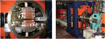
The first x-ray diffraction apparatus used for high pressure research was developed at Beijing Synchrotron Radiation Facility (BSRF) in 1993.[66] For almost ten years, the HP diffraction at BSRF time shared a beamline with other stations. The experiments carried out in DACs used energy dispersive diffraction mode.[19,67] The dedicated beamline for high pressure research at BSRF was built in the early 2000s, which used an in-vacuum permanent magnetic wiggler (4W2) as the x-ray radiation source. Figure
 | Fig. 1. Pictures of 4W2 in-vacuum wiggler at BSRF. (a) Inside view of wiggler, (b) installed in storage ring (Photos is provided by Shi C T). |
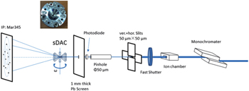
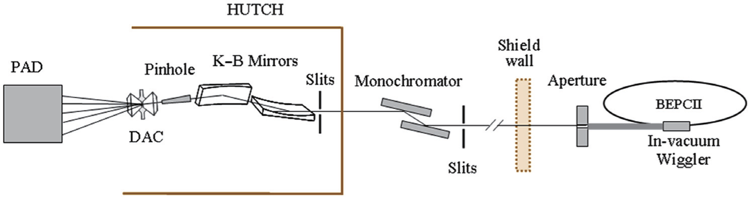 | Fig. 2. Schematic diagram of the 4W2 beamline at BSRF. |
We use two 100 mm long, actively bent mirrors in a Kirkpatrick Baez arrangement[59] to focus the monochromatic x-ray beam. The focusing quality depends mainly on the RMS slope error due to mirror misfiguring, static RMS slope error of the flat mirror and angular size of the source.[62,63] In the third generation synchrotron, high brightness (small angular divergence) of SR with sub-μrad slope errors of mirrors enables the focused beams to submicrometer size or smaller. As a first generation facility, the BEPC 4W2 has relatively large source size and large divergence. In our setup, the vertical mirror is only 18 meters from the source due to restrictions of the experimental hall space. In addition, the horizontal mirror cannot be very close to the sample because the high pressure vessels require a certain working distance. So it is difficult to focus the beam to several microns in size in the 4W2 beamline due to the large source size and small demagnification ratio. Focusing tests using 20 keV x-rays resulted in a double focused beam with a horizontal and vertical full width at half maximum (FWHM) of ∼ 25 μm × 10 μm, in which case the working distance is ∼ 80 mm. With this beam size, a lot of diffraction measurements under a megabar have been successfully carried out.[68,69] Longer working distance is required for the laser heating experiments and will result in an increase in spot size.
The x-ray diffraction can determine the d-spacings of different lattice planes (hkl) and then solve the crystal structure by Rietveld refinement. The x-ray diffraction condition is described by the following Bragg equation:


 | Fig. 3. Different diffraction geometry used with diamond anvil cell. (a) and (c) EDXRD, (b) and (d) ADXRD, and (e) Laue. |
The powder diffraction is the most common technique in high pressure research and is suitable for any sample form except single crystal. The high pressure powder diffraction experiment can be carried out by energy-dispersive method (EDXRD) or angle-dispersive method (ADXRD). The early HP powder diffraction experiments mainly adopt energy-dispersive techniques. In EDXRD method, polychromatic x-rays are used as the primary beam, and the scattered photons are detected by a solid state detector (SSD) with energy resolution which is held at one fixed angle, 2θ, as shown in Fig.
A critical factor determining the quality of diffraction data is the resolution, Δd/d (d is the d-spacing, and Δd its uncertainty). From Bragg equation, the uncertainty in the d-spacing determination depends on the deviations of Bragg angle, Δθ, and of x-ray energy, ΔE as follows:


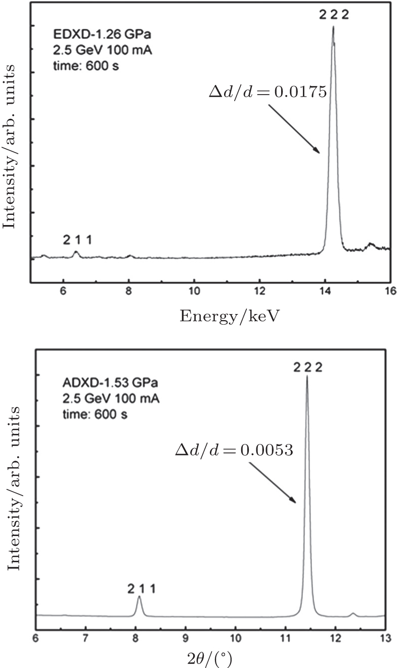 | Fig. 4. Diffraction profiles obtained from the same sample of Gd2O3 using energy-dispersive (a) and angle-dispersive (b) techniques. The patterns were recorded at 4W2 beamline of BSRF.[70] |
In spite of low resolution of EDXRD, it has been particularly useful for studying weakly scattering materials such as amorphous, liquid materials, and low-Z materials.[71–73] The advantage of this method is the excellent collimation, through which background scattering from surrounding materials (e.g., anvil, gasket, and medium) can be largely eliminated. Even though recently the energy dispersive diffraction mode has been replaced by the angular dispersive method in many HP beamlines, EDXRD is still an effective technique.
Powder x-ray diffraction is a well-developed crystallographic technique with synchrotron HP beamlines and widely used for high pressure research. Nevertheless, this technique has some intrinsic shortages, such as the overlapping of diffraction peaks, strong preferred orientation, low resolution, low ratio of signal to noise, and so on. In particular, positional information on reflections is lost to a great extent in powder diffraction, and thus full structural characterization is usually difficult for phases existing only under high-pressure conditions. Single crystal x-ray diffraction can measure three-dimensional data and there are no peak overlaps or preferred orientation problems, which provides more precise structural information than powder diffraction. From single crystal data, space groups and a structural model can be unambiguously determined. Single crystal x-ray diffraction has many advantages in resolving some very complex crystallographic structure.[74] In addition, the problem of weak diffraction intensity from light element materials can be partially overcome by the use of the single-crystal x-ray technique. The concentration of diffracted intensity in single-crystal reflections allows the measurements on some low-Z materials at very high pressures,[44,45,75] which is difficult to achieve using powder diffraction.
The collecting of single crystal diffraction data at pressures in an HP beamline can adopt EDXRD, ADXRD or Laue methods, as shown in Fig.
In single crystal XRD, the relative intensities of different Bragg reflections are measured. It is essential that the sample volume illuminated by the x-ray beam remains constant when the sample is rotated around ω and χ in the x-ray beam.[77] Carefully selecting the relative sizes of the incident beam and the sample crystal can achieve this criteria. There are two ways to choose depending on the ability of micro-focusing. In third-generation synchrotron facilities, with the developments in micro-beam technology x-ray beams can be focused down to a size comparable with single crystal grain (typically several microns). Usually the decision is that the crystal is larger than the incident x-ray beam. For example, on the 16-BM-D beamline at the advanced photon source (APS), the focused beam size is about 5 μm×10 μm full-width half-maximum (FWHM) in both horizontal and vertical directions, respectively.[56] The single crystal is normally cut into rectangular pieces with section size of approximately 20 μm×30 μm.[50] With this method, the illuminated volume of the crystal will change during the sample rotation. The correction of volume is needed in data analysis. Another method is adopting a larger x-ray beam which completely covers the smaller sample crystal. It is commonly used at first- or second-generation synchrotron light sources where the x-ray beam is not easy to focus so small. For example, on the 4W2 beamline at the BSRF, the focus beam size is close to 30 μm (FWHM) in the horizontal with K–B mirrors. The size of single crystal sample is usually smaller than 20 μm. In all cases, it is essential to ensure that the x-ray beam is centered on the sample crystal.
Single-crystal diffraction techniques have been developed at the high pressure beamline 4W2 at the BSRF. The sketch of the experimental set-up is shown in Fig.
 | Fig. 5. Schematic layout of beamline components for HP single crystal diffraction at BSRF (supported by Hui Li). Insert is a specially designed DAC for single crystal diffraction. |
The diamond anvil cell is a uniaxial stress device, as shown in Fig.

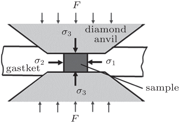 | Fig. 6. Stress state of the uniaxially compressed sample in a diamond anvil cell. |
The existence of differential stress, t, makes the samples in DAC always subjected to a nonhydrostatic compression which can strongly affect the measured lattice strains. Although the quasihydrostatic conditions can be obtained with pressure medium around the sample, a completely hydrostatic environment cannot be sustained above ∼ 15 GPa due to the freezing of all known pressure media. In the conventional diffraction experiments using a DAC, the primary x-ray beam passes parallel to the load axis, as shown in Fig.
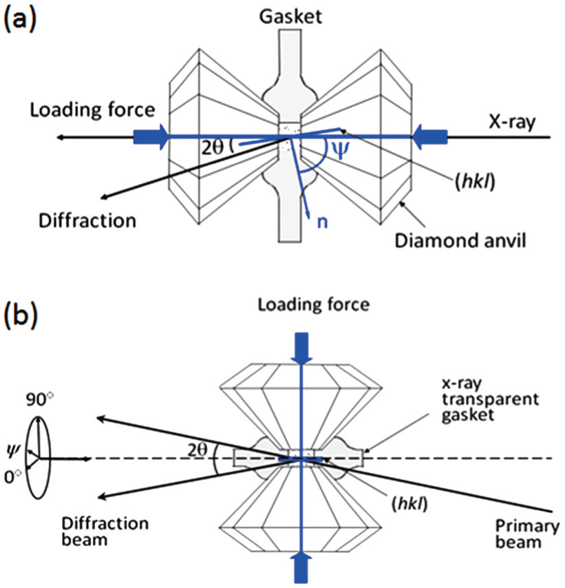 | Fig. 7. (a) Axial x-ray diffraction geometry; (b) radial x-ray diffraction geometry. |
In the radial diffraction geometry, the primary x-ray beam passes in close to perpendicular to the load axis direction, as shown in Fig.

Using the radial XRD technique together with lattice strain theories, it is also possible to obtain useful information that is unavailable with hydrostatic experiments, such as the strength, elasticity, rheology, and texturing. The slope Q(hkl) in Eq. (

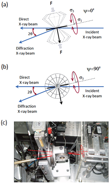
Both radial XRD techniques using EDXRD and ADXRD respectively have been developed at BSRF. In energy-dispersive RXRD experiments, the diffracted intensity was recorded using a Ge solid-state detector with a fixed angle, 2θ. The diamond-anvil cell is mounted in a rotation stage whose axis bisects 2θ, as shown in Fig.
 | Fig. 8. Experimental geometry for energy-dispersive radial diffraction. The ψ is the angle between the diamond cell stress axis and the diffraction plane normal. (a) ψ = 0°, diffraction plane normal parallel to the diamond cell stress axis; (b) ψ = 90°, diffraction plane normal perpendicular to stress axis. (c) Photograph of experimental setup at BSRF, a symmetric DAC is used. |
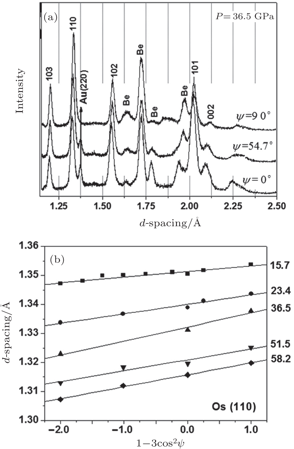 | Fig. 9. Radial diffraction of osmium. (a) The x-ray diffraction patterns taken at ψ = 0°, 54.7°, and 90° under 36.5 GPa. (b) Dependence of d-spacing on 1 − 3 cos2 ψ for diffraction line (110). The solid lines are least-squares fits to the data. The pressure is determined from the lattice parameter of gold observed at ψ = 54.7°.[91] |
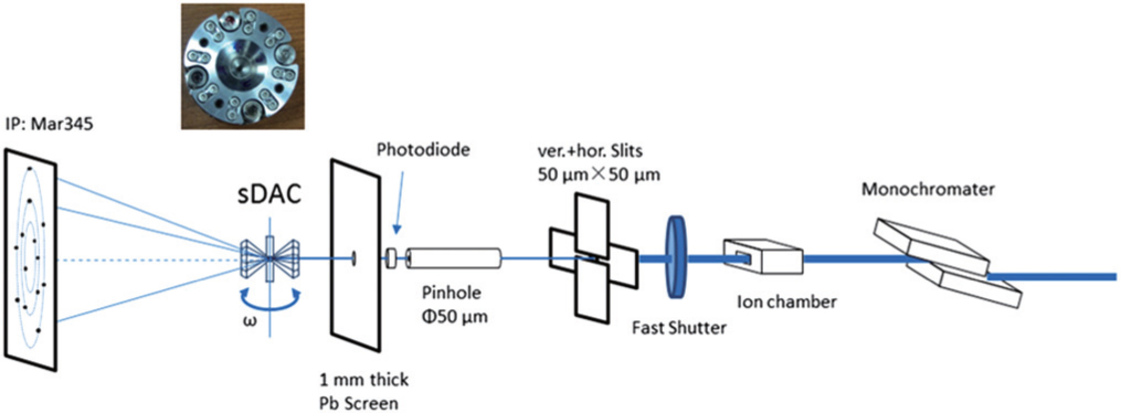
In a general angle-dispersive radial x-ray diffraction experiment, the incident x-ray is perpendicular to the compression axis and passes through a beryllium gasket, as shown in Fig.
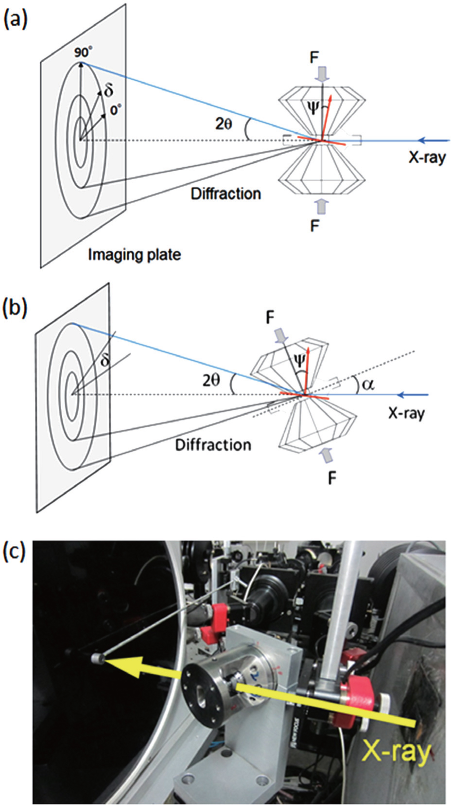 | Fig. 10. Schematic of experiment for angle-dispersive radial diffraction. (a) Diffraction geometry: incident beam perpendicular to the compression axis; (b) diffraction geometry: compression axis tilts angle α; (c) photograph of experimental setup at BSRF, a panoramic DAC is used. |
The ψ corresponding to the angle between the diffracting plane normal and the loading axis is calculated using the equation[40]


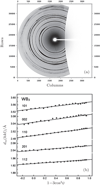
As an example, a diffraction pattern of tungsten triboride (WB3) from angle-dispersive radial diffraction is shown in Fig.
 | Fig. 11. (a) Angle-dispersive radial diffraction pattern of WB3 at 45 GPa. The DAC was tilted 28°; (b) the d-spacings versus 1 − 3 cos2 ψ for selected diffraction peaks of WB3 at 45 GPa. The data were obtained with integrations over 5° intervals of the azimuth angle from 180° to 270°. The solid lines are least-squares linear fits to the data. The pressures are determined from the Mo (110) peak at ψ = 54.7°.[92] |
An x-ray measurement at simultaneous pressure and temperature provides us with various important information on the behavior of materials and their crystal structures under extreme conditions. With further development and application of synchrotron light sources, an important extension of the high pressure experimental techniques using synchrotron involves the coupling of high or low temperature techniques with polycrystalline diffraction. These techniques provide an in situ measure of crystal structures at P–T conditions which provide fundamental information for understanding physical properties of materials.
Conventional diffraction systems with DAC can be readily combined with variable-temperature studies, including low-temperature cryogenic methods and high-temperature resistive heating techniques (both external and internal) as well as laser-heating methods. By using a continuous wave (cw) laser heated diamond anvil cell (LHDAC), it is not difficult to heat the sample reaching much higher temperature (T > 1500 K) at high pressure (P > 100 GPa). Because of this advantage, many high pressure diffraction beamlines have been equipped with laser heating systems at various synchrotron facilities in the world.[26–31,95,96]
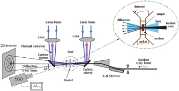
A typical configuration of x-ray diffraction combining with the laser heating technique in a high-pressure cell is shown in Fig.
 | Fig. 12. A typical configuration of x-ray diffraction combining with a laser heated DAC. |
For in situ diffraction experiments on laser-heated diamond-anvil cell samples, a perfect alignment is required, with all heating laser beams, thermal radiation paths, incident x-ray beams, and characterizing systems aligned to the sample position within a few microns. The insert in Fig.
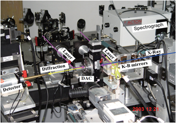
A double laser-heating system has been developed at 4W2 beamline of BSRF. Figure
 | Fig. 13. The in situ experimental setup for high pressure and temperature diffraction. The figure shows an EDXRD system combined with the double-laser heating system in DAC. The spectrograph is used for temperature measurement. |
The laser heating technique with x-ray diffraction has evolved into a routine experimental method for in situ measurements under extreme conditions. Over the last decade, this technique has been widely used for high P–T studies such as phase transition studies,[23,100–104] high pressure melting,[103–108] syntheses of high P–T phases,[109–112] and P–V–T equations of state.[28–31] Recently, the phase transition sequences of the rare earth manganites, indates and gallium garnets have been investigated in a laser-heated diamond anvil cell using synchrotron radiation x-ray diffraction at BSRF.[69,98,117–119] The studies provide more understanding of the phase transition mechanisms in these rare earth compounds at high pressure and temperature.
With the developments of micro-beam technology in synchrotron radiation and the use of area detector, HP single crystal diffraction technique has been greatly developed in both measurements and applications. Single-crystal XRD provides the most precise structural information that can be used to uniquely determine the space group and structural model. However, a single crystal sample in a DAC is usually crushed into many particles under higher pressure. On the other hand, single crystals fail to survive after a pressure-induced phase transition. A common method for reformation of the single crystal is promoting grain growth by heating the sample in the high pressure phase but it often results in highly spotty XRD patterns. Therefore, so far the structural studies under higher pressure have been limited to powder diffraction techniques.
Newly developed multigrain single-crystal x-ray diffraction analysis technique in a diamond anvil cell can overcome these limitations. With the developments of microbeam technology in synchrotron radiation, the minimal size needed for single-crystal diffraction has been reduced to around 1 mm. Traditional powder sample may be treated as multiple grains. A novel analytical approach known as multigrain crystallography is applied for structure determination of multi-grain and the quality of the resulting refinements is comparable to single crystal work.[47,120] This method is applicable for samples with up to a thousand grains, a few hundred grains and about ten grains, respectively. The multigrain XRD is a very promising method for high pressure crystallography research and has been used in studies of deep Earth materials.[76,121]
The recent development of single crystal diffraction techniques has achieved a significant extension of the application for high pressure research. Over the past few decades, single crystal diffraction was mainly used for structure solution and refinement. Using the recently developed single crystal x-ray diffraction technique, besides the information on atomic arrangement the information on electronic structure under pressure can be obtained. By using the maximum entropy method (MEM), the resultant single crystal diffraction data has been used to determine the electron density distribution under high pressure.[49,50,78] Preliminary results in germanium suggest that the pressure-induced phase transformation is related to the electronic changes before the structural phase transition. This new capability of single crystal diffraction provides an approach to further understand the mechanism of electronic structure phase transitions.
So far, high pressure diffraction experiments in a DAC are mainly carried out at a static pressure condition, i.e., using opposed anvils to exert a fixed pressure on the sample. However, once the applied force is constant, the final pressure in the material studied is reached with a delay depending on the driving mechanism of DAC. This time dependence strongly influences the phase transformation pathways. Recently, a dynamic DAC (dDAC) has been developed for fast compression and decompression,[122,123] which uses electromechanical piezoelectric (PZT) actuators or pneumatic membrane to replace screws in the DAC. Various compression rate can be obtained by controlling the change speed of driving voltage (PZT) or gas-pressure (membrane). In particular, this capability covers the regions of compression rates between static techniques (DACs and large volume presses) and dynamic shock-driven devices (gas guns, explosive, and laser shock) that have been sparsely studied. Coupling dDAC with fast x-ray detectors, such as Pilatus and Eiger, time-resolve HP x-ray diffraction can be performed at various compression rates,[51] which allows studies of the kinetics of phase transitions, phase growth, and metastable phases.
Another development area is the modulated heating. Pulsed laser heating in diamond anvil cells has recently attracted interest.[123,124] The short heating duration can effectively suppresses thermally activated chemical diffusion and reaction, reaching even higher temperatures compared to continuous wave laser heating. A laser pulse can be synchronized with gated x-ray detector, such as Pilatus, and time-resolved radiometric temperature measurements. This new laser heating technique preserves a great potential for the accurate measurement of melting curves, phase transition relations, thermal diffusivity, and pressure-volume-temperature equations of state.
Recent advances at synchrotron radiation facilities have made the developments of various synchrotron techniques for high pressure research possible. Among these, x-ray diffraction remains the basic experimental method. With enhancement in source brilliance and the improvement in micro-focusing techniques, powder XRD has provided structural information with improved precision and accuracy up to multi-megabar pressures. With the introduction of radial diffraction geometry, powder diffraction in DAC has been extended to measure strength, elasticity, deformation, and rheology of materials. HP single-crystal diffraction method using monochromatic beams and area detectors can provide accurate structure determination, as well as the information of electron density distribution. With the developments in micro-focusing technology in synchrotron radiation, a new crystallography for multi-grains data has been recently developed resulting in the quality of refinements comparable with single-crystal work. ADXRD provides improved resolution, typically at Δd/d of around 3 × 10⁻³–5 × 10⁻³, which has become the dominant approach for structural studies at high pressure. Even so EDXRD is still particularly useful for studying weakly scattering materials such as amorphous, liquid materials and low-Z materials. Laser heating technique can couple with ADXRD or EDXRD and has evolved into a routine experimental method in HP beamlines that is widely used for high P–T studies such as phase transition studies, high pressure melting, syntheses of high P–T phases, and P–V–T equations of state. Recently emergence of fast gated detectors and development of dynamic DAC make the time-resolved XRD measurement under high pressure possible, which is a very promising approach for the future high pressure research. The XRD with synchrotron radiation has long been the dominant method for materials research under high pressure, and is likely to remain so in the future.
| 1 | |
| 2 | |
| 3 | |
| 4 | |
| 5 | |
| 6 | |
| 7 | |
| 8 | |
| 9 | |
| 10 | |
| 11 | |
| 12 | |
| 13 | |
| 14 | |
| 15 | |
| 16 | |
| 17 | |
| 18 | |
| 19 | |
| 20 | |
| 21 | |
| 22 | |
| 23 | |
| 24 | |
| 25 | |
| 26 | |
| 27 | |
| 28 | |
| 29 | |
| 30 | |
| 31 | |
| 32 | |
| 33 | |
| 34 | |
| 35 | |
| 36 | |
| 37 | |
| 38 | |
| 39 | |
| 40 | |
| 41 | |
| 42 | |
| 43 | |
| 44 | |
| 45 | |
| 46 | |
| 47 | |
| 48 | |
| 49 | |
| 50 | |
| 51 | |
| 52 | |
| 53 | |
| 54 | |
| 55 | |
| 56 | |
| 57 | |
| 58 | |
| 59 | |
| 60 | |
| 61 | |
| 62 | |
| 63 | |
| 64 | |
| 65 | |
| 66 | |
| 67 | |
| 68 | |
| 69 | |
| 70 | |
| 71 | |
| 72 | |
| 73 | |
| 74 | |
| 75 | |
| 76 | |
| 77 | |
| 78 | |
| 79 | |
| 80 | |
| 81 | |
| 82 | |
| 83 | |
| 84 | |
| 85 | |
| 86 | |
| 87 | |
| 88 | |
| 89 | |
| 90 | |
| 91 | |
| 92 | |
| 93 | |
| 94 | |
| 95 | |
| 96 | |
| 97 | |
| 98 | |
| 99 | |
| 100 | |
| 101 | |
| 102 | |
| 103 | |
| 104 | |
| 105 | |
| 106 | |
| 107 | |
| 108 | |
| 109 | |
| 110 | |
| 111 | |
| 112 | |
| 113 | |
| 114 | |
| 115 | |
| 116 | |
| 117 | |
| 118 | |
| 119 | |
| 120 | |
| 121 | |
| 122 | |
| 123 | |
| 124 |