
Generalized model for laser-induced surface structure in metallic glass
[Ye Lin-Mao1, Wu Zhen-Wei1, 2, Liu Kai-Xin1, 2, †,  , Tang Xiu-Zhang3, Xiong Xiang-Ming1]
, Tang Xiu-Zhang3, Xiong Xiang-Ming1]
|
|


† Corresponding author. E-mail:
Project supported by the National Natural Science Foundation of China (Grant Nos. 10572002, 10732010, and 11332002).
The details of the special three-dimensional micro-nano scale ripples with a period of hundreds of microns on the surfaces of a Zr-based and a La-based metallic glass irradiated separately by single laser pulse are investigated. We use the small-amplitude capillary wave theory to unveil the ripple formation mechanism through considering each of the molten metallic glasses as an incompressible viscous fluid. A generalized model is presented to describe the special morphology, which fits the experimental result well. It is also revealed that the viscosity brings about the biggest effect on the monotone decreasing nature of the amplitude and the wavelength of the surface ripples. The greater the viscosity is, the shorter the amplitude and the wavelength are.
Laser-induced periodic surface structures (LIPSSs) for various materials, such as metals and semiconductors, have been well studied[1–6] by the scientific and engineering community since laser operating devices were invented. Some unique micro-nano scale surface structure irradiated by laser has also been discovered. As the fabrication of the micro-nano scale surface structure has been well used in many fields,[7–12] the morphological formation mechanism of the structure has attracted a great deal of attention.[13–16] Based on previous researches, the fluence of the laser is considered as one of the major factors for the formation of LIPSSs, which mainly affects the generated surface electromagnetic wave or the capillary wave on the surface.[1,13] However, there are different structures appearing on the surface for various materials under the same laser condition. The properties of the material should also be an important factor for the formation mechanism, which is less discussed.
Bulk metallic glass (BMG) with excellent features[17,18] like high strength, good magnetic properties and corrosion resistance processed by pulse laser has a more complex surface phenomenon than many other materials. As described in our previous work,[14] there are especially novel concentric rippling wave structures on the surface of BMG irradiated by pulse laser. The wavelength and the amplitude decreased from the inside to the outside. Liu et al.[15] gave a model to predict the characteristic interval of the ripples via perturbation analysis. However, there are no unified models for the whole ripple structures and few investigations into the effect of material properties on the morphological formation mechanism. Making clear the special surface structural evolution of BMGs induced by single laser and the effect of the properties of BMGs will be helpful for understanding the BMGs in physics and materials science, which show a series of improved features, interesting phenomenon, and practical applications.
In this work, the three-dimensional (3D) surface morphologies of a Zr-based and a La-based metallic glass irradiated separately by nano-second single pulse laser are scanned by atomic force microscopy (AFM). Based on the experimental result, we give a generalized theoretical model for describing the surface morphology of the BMG irradiated by laser, which is based on the hydrodynamics of a small-amplitude capillary wave propagating in deep water by considering BMG as an incompressible and high viscosity fluid. The experimental results agree with the results from our model very well. It is also revealed that the high viscosity of BMG is more important for forming the special ripples than the different experimental results of the two kinds of materials.
As described in our previous work,[14] two kinds of special BMGs Zr55Cu30Al10Ni5 (at.%) and La55Ni20Al25 (at.%) were prepared by the arc melting and drop-casing method, and cut into cylindrical targets, each with diameter 5 mm and height 5 mm, by wire electrode cutting. The specimen surfaces were polished until the roughness was less than 30 nm. The amorphous material nature was also confirmed by x-ray diffraction (XRD) as well as differential scanning calorimetry (DSC) with a heating rate of 20 K/min. Then, a single pulse Nd: YAG solid state laser with wavelength 532 nm, pulse width 10 ns and the maximum energy 1 J was used to irradiate the polished target surface at room temperature. After irradiation, another XRD experiment was performed to test the amorphous nature, and the two-dimensional (2D) and 3D surface morphology were observed by scanning electron microscopy (S-4800) and atomic force microscopy Dimension ICON, respectively.
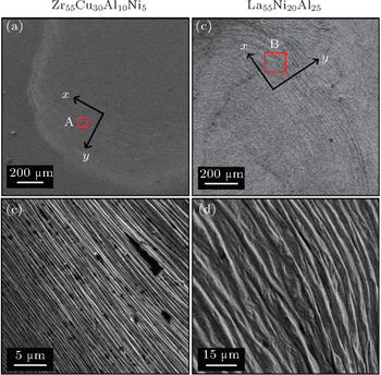
Figure
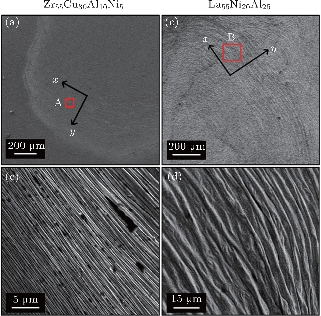 | Fig. 1. Micrographs of the surface morphology of Zr55Cu30Al10Ni5 ((a) and (b)) and La55Ni20Al25 ((c) and (d)) irradiated by a single pulse laser with an intensity of about 5.5×10¹² W/m2. Panels (a) and (c) show the entire SEM view of the irradiated area, panel (b) displays the close-up view of the area “A” marked in panel (a), and panel (d) exhibits the close-up view of the area “B” marked in panel (c). |
The values of the wavelength change from 10 μm inside to 1 μm outside. The later XRD experimental results show that the material still holds the amorphous characteristic.
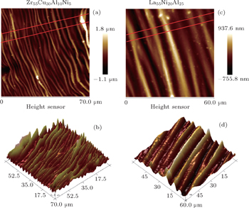
In order to make further study on the formation of the special surface patterns, detailed AFM observations of the ripple structure are shown in Fig.
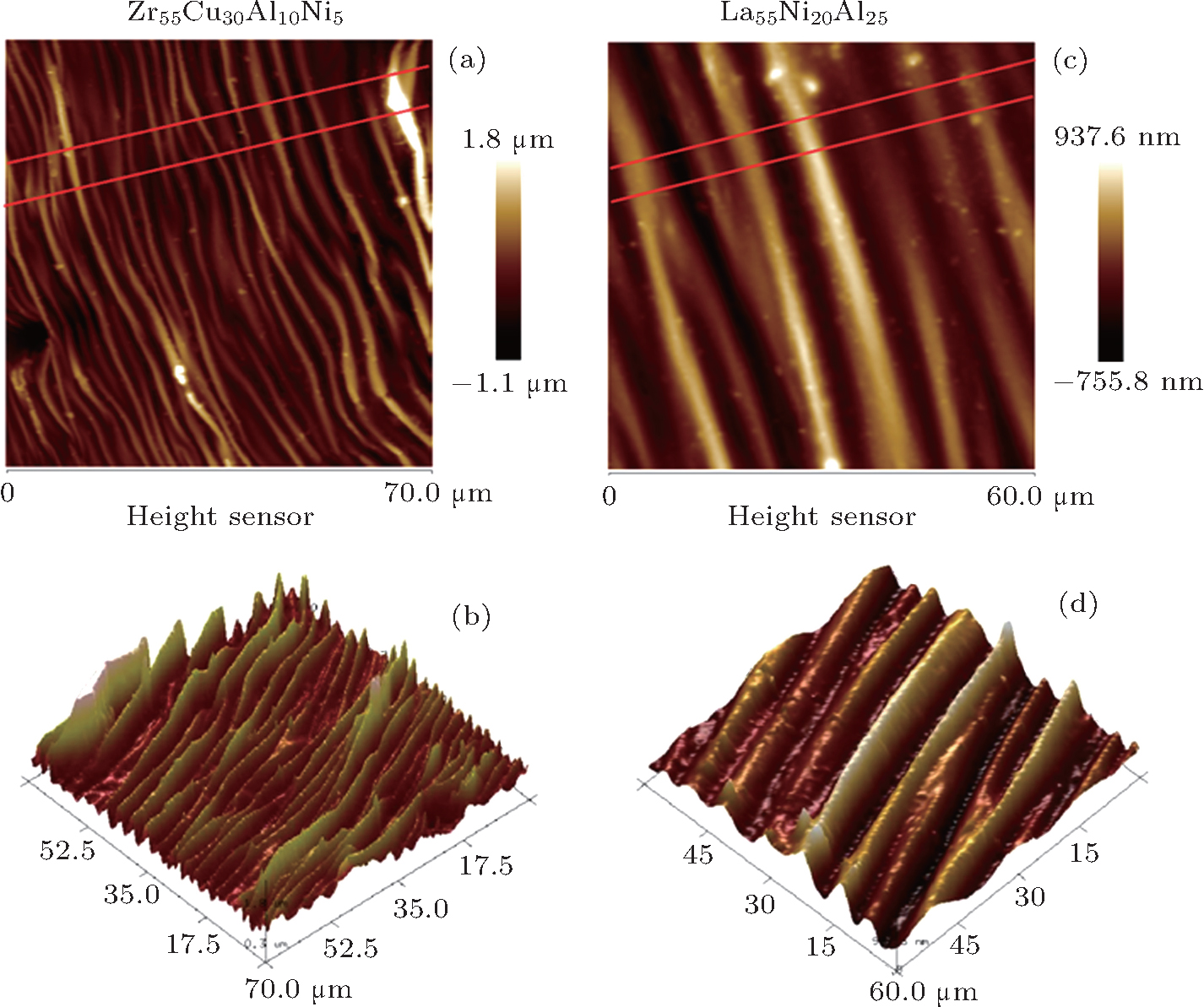 | Fig. 2. AFM images for Zr55Cu30Al10Ni5 ((a) and (b)) and La55Ni20Al25 ((c) and (d)). Panels (a) and (c) show the 2D details near the middle part of the ripples, and panels (b) and (d) display the 3D details corresponding to panels (a) and (c), respectively. |
The statistical experimental and the analytical fitting results for the amplitude, the wavelength and the whole ripples are all shown in Figs.
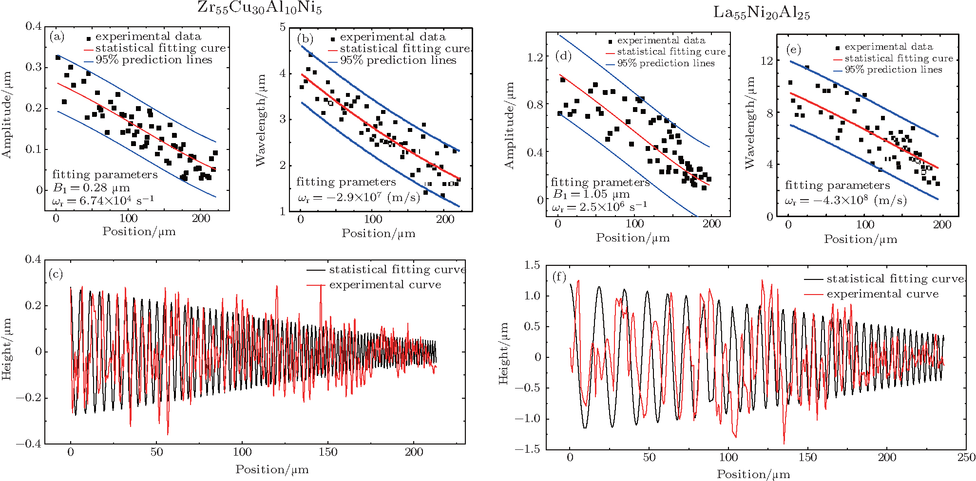 | Fig. 3. Experimental data and the theoretical statistical data along the x direction of the wave such as the red exemplificative lines shown in Figs. |
When BMGs are irradiated by the single high energy laser, its surface in the radiated zone absorbs large amounts of energy, which leads to the temperature rising up to glass transition temperature in a very thin layer. The intensity of the laser conforms to spatial Gaussian distribution, which can be given as[19]


As the amplitude attenuates rapidly and nearly disappears on the edge observed in Fig.
As shown in previous experimental studies,[23–26] the viscosity of the melting BMGs alloys is very large. In our experiment, the magnitudes of the following characteristic coefficients are μ > 10−1 Pa·s,[20] σ0 ∼ 100 N/m,[13] and g ∼ 101 m/s2, so there is |μ∇2v| ≫ |σ0∂2v/∂x2| ≫ |g|, where μ is the viscosity coefficient, σ0 is the surface tension coefficient, and g is the acceleration vector of gravity. The viscosity can be considered as a main reason for forming the surface morphology. As there are more than a hundred cycles and the amplitude and the wavelength of the surface ripples are very small and almost unchanged in several adjacent cycles, we can assume that the viscosity and surface tension coefficient to be constant in each cycle. In other words, the conditions in each cycle can be regarded as being constant. In the following, we solve the problem for each cycle. According to the hydrodynamics theory, there are the approximate conditions |v| ∼ h/C, |∂v/∂t| ∼ h/C2, and |(v·∇)v| ∼ h2/λC2 (C, h, and λ are the period, amplitude and wavelength of the wave, respectively) for small-amplitude capillary surface wave in the deep liquid.[27,28] The external force term, the nonlinear speed term and the gravity term can be ignored in comparison with the linear and the surface tensor ones. Then the governing equations can be given with the original point defined on the edge of the irradiation central area, which is the starting point of the ripples. The x axis is along the wave propagating direction on the surface, and the z axis is downwards perpendicular to the x axis. The molten BMGs are regarded as being an incompressible and viscous fluid. The governing equations in each independent cycle can be simply given in Euler coordinates as


As equation (

Assuming that ρω/k2μ ≪ 1, there is b ∼ k and k can be approximately given as


While referring to the whole rippling morphology on the surface, neither the amplitude nor the wavelength of the wave in spatial scale is constant but decreases gradually from the inside to the outside, which is mainly caused by the temperature-dependent viscosity. We assume that the time scale for the solution is constant as τ0 and the variable viscosity coefficient on the surface, changes only in the x direction, which is defined as μ(x). Then the circular frequency ωr and the corresponding time attenuation ωi, which are both parameters of time scale, can also be regarded as being constant when the sample solidifies. Inserting Eq. (


The viscosity depends on the temperature T and obeys the Vogel–Fulcher–Tammann (VFT) relationship.[23–26] It is expressed as μ = μ0exp(A0/(T − T1)), where μ0, A0, and T1 are three VFT constants. It can be assumed that the time scale in Eq. (
Referring to earlier work[14,15,21–26,29] and our experimental data, one could use Ta ≈ 300 K, α ≈ 0.1, τ0 = 1 × 10⁻⁸ s, r0 ≈ 1.0 × 10⁻³ m, R0 ≈ 1.25 × 10⁻³ m, I0(τ0) ≈ 5.5 × 10¹² W/m2, ρZr ≈ 6400 kg/m3, cZr ≈ 1200 J/(kg·K), σ0Zr ≈ 0.85 N/m, KZr ≈ 100 W/(m·K), A0Zr ≈ 8531 K, μ0Zr ≈ 9.36 × 10⁻⁵ Pa · s, and T1Zr ≈ 383.1 K for Zr-based BMG for the simulation, with ignoring the temperature effect on the parameters as they change little in our experiment. According to the above analysis and fitting the experimental data to Eqs. (
The experimental and the statistical fitting results of the ripples on the surface are shown together in Fig.
In this work, following ns pulse irradiation, a type of dense micro-nano scale ripple pattern with a period of hundreds of microns on the surface is produced. The formulation of the ripples is the result of the small-amplitude capillary wave propagating in an infinite metallic glass forming a supercooled liquid pool. Based on hydrodynamics, a generalized theory can be given to unveil the ripples forming mechanism in metallic glass. In our experiment, the characteristics of monotonically reducing the amplitude and wavelength of the special ripples mainly depend on the high viscosity of the molten BMGs. The greater the viscosity, the smaller the amplitude is and the shorter the wavelength. It can be concluded further that the generation and the features of the special morphology are primarily dependent on the characteristics of laser, material, especially viscosity for BMGs. This research can also help us quantitatively obtain the desired micro and nano surface structures by adjusting the laser parameters and choosing suitable BMGs materials.
| 1 | |
| 2 | |
| 3 | |
| 4 | |
| 5 | |
| 6 | |
| 7 | |
| 8 | |
| 9 | |
| 10 | |
| 11 | |
| 12 | |
| 13 | |
| 14 | |
| 15 | |
| 16 | |
| 17 | |
| 18 | |
| 19 | |
| 20 | |
| 21 | |
| 22 | |
| 23 | |
| 24 | |
| 25 | |
| 26 | |
| 27 | |
| 28 | |
| 29 |