Alternating-current relaxation of a rotating metallic particle
Nie Guo-Xi1, Tian Wen-Jia1, 2, Huang Ji-Ping1, †, , Gu Guo-Qing3
Department of Physics, State Key Laboratory of Surface Physics, and Collaborative Innovation Center of Advanced Microstructures, Fudan University, Shanghai 200433, China
Polar Research Institute of China, Shanghai 200136, China
School of Information Science and Technology, East China Normal University, Shanghai 200062, China


† Corresponding author. E-mail: jphuang@fudan.edu.cn

Project supported by the National Natural Science Foundation of China (Grant No. 11222544), the Fok Ying Tung Education Foundation (Grant No. 131008), the Program for New Century Excellent Talents in University, China (Grant No. NCET-12-0121), and the National Key Basic Research Program of China (Grant No. 2011CB922004).

Abstract
Abstract

Based on a first-principles approach, we establish an alternating-current (AC) relaxation theory for a rotating metallic particle with complex dielectric constant . Here is the real part, the conductivity, ω0 the angular frequency of an AC electric field, and . Our theory yields an accurate interparticle force, which is in good agreement with the existing experiment. The agreement helps to show that the relaxations of two kinds of charges, namely, surface polarized charges (described by ) and free charges (corresponding to ), contribute to the unusually large reduction in the attracting interparticle force. This theory can be adopted to determine the relaxation time of dynamic particles in various fields.

PACS: 72.15.Lh;45.20.dc
1. Introduction

The structures of various systems, such as colloidal suspensions including electrorheological fluids,[13] magnetorheological suspensions,[47] ferrofluids,[811] living cells suspensions,[12] and so on, are very sensitive to the change of interparticle forces. Unfortunately, some shearing flow that is inevitable in experiments and natural environments can cause the rotation of the colloidal particles,[1323] thus reducing the interparticle force to some extent. An interaction between a rotating electric field and suspended particles or cells can also lead to a rotational motion of the particles. This phenomenon, known as electrorotation, has been increasingly employed as a sensitive tool for noninvasive studies of a broad variety of microparticles, ranging from living cells to nanowires, seeds as well as synthetic materials.[2429] In addition, insulating particles suspended in a liquid with low conductivity can also rotate in the presence of an electric field, which leads to the so-called negative effective viscosity effect.[30,31]

The dielectric relaxation can affect the inter-particle force, and even the property of the semi-conducting materials.[3234] So far, the relaxation of polarized charges in dielectric particles has been investigated within the well-known Maxwell–Wagner relaxation theory. However, it was shown that the Maxwell–Wagner relaxation time is valid for an isolated stationary dielectric sphere or infinite large plank, whose dielectric responses are represented by a dielectric constant and electric responses by a conductivity.[35]

When a dielectric particle starts to rotate, the polarization charges tend to deviate from the original position due to the rotation of the dielectric particle. On the other hand, the charges tend to return to the original position due to the directed external field. Thus, at dynamic equilibrium, the two competitive effects can change the polarization charge distribution. As a result, this change affects the interaction between the two particles one of which is rotating. The same process also happens when a metallic particle substitutes for the dielectric one. However, for the extremely high conductivity of the metallic material, it is believed that free charges on the surface of the metallic particle will not cause an obvious force decrease in a low rotation speed. On the contrary, Tao and Lan[36] experimentally reported that the rotation of a metallic particle can reduce significantly the attracting interparticle force between the rotating metallic particle and a stationary dielectric or metallic one in argon gas. To the best of our knowledge, this was the first direct experiment conducted on the interparticle force between two touching rotating particles. Tan et al.[37] found that the local electric field between two metallic particles weakens as one rotates faster, which can be used to qualitatively explain the phenomenon of Tao and Lan’s work.[36] However, a quantitative explanation is still lacking for explaining Tao and Lan’s observations,[36] which is important for practice. To solve this, we believe that the relaxation processes in dynamic metallic particles should be understood carefully, which are also expected to receive a broad interest in various fields related to dynamics in (soft) condensed matter. Reference [38] described a method to solve similar systems. However, only dielectric particles were under their consideration. In this work, we improve the method in Ref. [38]. Based on a first-principles approach, we establish a relaxation theory for dynamic metallic particles in the presence of an external AC field, thus being called AC relaxation theory.

This paper is organized as follows. In Section 2, we establish an AC relaxation theory for dynamic metallic particles on the basis of a first-principles approach. In Section 3, the comparison between theory and experiment is presented, which is followed by a conclusion in Section 4.

2. Formalism
2.1. Static charge distribution

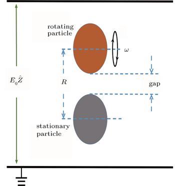
Let us consider two spherical particles in an external electric field , one of which is held fixed. The other one rotates around the axis perpendicular to the line joining the centers of the two particles with the rotation frequency, ω, see Fig. 1.

Fig. 1. Schematic graph showing two spherical particles in an external AC electric field, , one of which is held fixed and the other of which rotates around the axis perpendicular to the line joining the centers of the two particles with the rotation frequency, ω. R represents the center-to-center distance between the two particles, and “gap” denotes the surface-to-surface separation between the two particles.

The value of ω can be controlled artificially (e.g., the rotating particle may be connected to a motor[36]). In spherical coordinates, the electric potential Φ satisfies the Laplace equation and the general expressions for Φh(rα) in the host region in the vicinity of particle α can be written down as[39]

and the potential inside particle α, Φi(rα), is[39]

where Pl are the Legendre polynomials. There is no coordinate component φ, for we simply assume the rotating symmetry. The coefficients , , and are yet to be determined.

Applying the boundary conditions, i.e., the continuity of the potential and the electric displacement on the surface of particles, we obtain two sets of relations between the unknown coefficients:

where

Here εα and εh are the dielectric constants of particle α and the host, respectively, and aα is the radius of particle α.

Since we try to introduce the effect of free charges which may exist on the surface of metallic particles, the conductivity of the particle should be considered. In that case, the complex dielectric constant εα can be written as

where is the real part of the complex dielectric constant, the conductivity of the metallic particle, ω0 the angular frequency of the applied AC electric field, and . Consequently, the potential Φi(r) inside a particle consists of a real part ΦR,i(r) and an imaginary part ΦI,i(r) as

The polarized and free charge distributions σst on the surface of the metallic particle are related to the discontinuity in the electric field across the surface through

In the calculation below, we deal with the complex parameters directly.

The remaining unknown coefficients can be found by constructing a set of Rayleigh identities by the Green function formulation. According to the Green function approach,[39] the effects of the polarized charges on the potential at any location can be written as

Here rβ is a position vector originated from the center of particle b to the same location as rα. The parameter q(R) represents the surface polarized charge, which is obtained from Eq. (8) in our system.

Comparing Eqs. (1), (2), and (9), which represent two different ways of describing the same quantity in regions occupied by the particles, we obtain a pair of Rayleigh identities given by

In the experiment of Ref. [36], the two particles were arranged along the direction. To comply with this, in the current work we also set the applied electric field to be -directed (Fig. 1). Consider the origin at the center of particle α, i.e., rα = 0, and rβ = R (here R is the distance between the centers of the two particles). Taking the partial derivatives of Eq. (10) with respect to r, we obtain a set of linear equations for the unknown coefficients

Thus, all the coefficients , , and in the potential are determined. Please refer to Ref. [38] for more detailed derivation. We can get the first-order parameters

Here ω0 is the frequency of the applied field. For particles with different dielectric constant and radius, the coefficients and are different. Furthermore, we can write the surface charge of a stationary particle as

where the first-order term is

The parameters are complex forms as described by Eq. (6).

2.2. Charge distribution on rotating particles

Once the rotation appears, the displaced original polarized and free charge distributions deviate from the static distribution. The distribution will tend to relax to an equilibrium distribution at a certain rate 1/τ where τ means the relaxation time, which is dependent on the material forming the particles, the geometry of the particles, and some other elements like rotation speed and circumstance. Here, according to Eq. (6), the relaxation time τ can be separated as τR and τI. The former (τR) results from and the latter (τI) is due to . That is, they are related to surface-polarized charges (σR) and free charges (σI), respectively. The time-dependent σR(θ,φ,t) and σI(θ,φ,t) on a rotating metallic particle satisfy the following two equations

where t is time, and θ or φ is the polar angle in the spherical coordinates (r,θ,φ) with the origin being located at the center of the rotating particle. In our system, the axis of rotation is perpendicular to the applied field and the line joining the centers of the particles (Fig. 1), and the charge re-distribution due to rotation possesses symmetry break, yielding the dependence of charge distribution on φ. However, its correction to interaction forces was found to be small enough to be neglected, according to the method presented in Ref. [40]. Thus, in what follows, the dependence on φ will be dropped. We can use coefficients to expand the charge distribution σ(θ) on the rotating particle in terms of Legendre polynomials

where are related to the other coefficients we calculated in Subsection 2.1. By obtaining the surface charge distributions, we are able to achieve the potential inside or outside particles, when one of them is rotating.

2.3. Force exerted on rotating particles

The force exerted on a particle can be found by evaluating the derivative of the energy with respect to particle displacement in space. The change in electrostatic energy due to the introduction of particles into the host medium in the presence of an electric field E0 is[39]

where εα stands for the complex dielectric constant of particle a and b, respectively. Here, Re [⋯] denotes the real part of ⋯, D represents the electric displacement, and the local field E is given by E = −∇Φ. Let Wst,α be the change in energy due to the presence of particle α but the particle is kept stationary. The first-order energy of a stationary particle is

where V is the volume of the particle under consideration. The comparison between Wα and Wst,α leads to the following relation

where ζ is a coefficient varying in different systems.

Now, by taking the derivative of the energy, a formula relating the angular velocity ω of the rotating particle to the induced force F on the particle is then obtained as

where Fst represents the interparticle force when both particles are at rest. By performing calculations, the exact value of the coefficient ζ is found to be

Here, we only keep the first three terms in our numerical calculation for each relaxation time, and the contributions from all the other terms are small enough to be neglected. The coefficients VR, VI, JR, JI, and Ge are respectively given by

where

In Eqs. (13) and (21), the constants Hl can be calculated by the method in Subsection 2.1. In these equations, ζ is related to the rotation frequency ω. When both particles are at rest, we have ζ = 1. The rotation causes ζ to have different values, thus yielding FFst.

3. Comparison between theory and experiment

In the experiment,[36] two spherical particles of diameter 19.06 mm were arranged vertically inside a capacitor composed of two horizontal electrodes. One of the particles, which could move up and down to adjust the gap between particles, was connected to a motor and was able to rotate around the horizontal axis. Another one rested on a microbalance. The whole device was placed inside a glove box, which was filled with dry argon gas. When there was no electric field, the reading on the microbalance was just the weight of the stationary particle. When an electric field was applied, the induced attracting force between the rotating metallic particle (cooper) and the stationary metallic particle (cooper) or the dielectric one (polyamide) reduced the reading on the microbalance. Thus, the attracting force between the two particles was able to be determined.

Now we are in a position to compare theory and experiment. For this purpose, consistent with the experiment,[36] the diameters of particles are also set to be 19.06 mm. The distance between the centers of the two particles, R, which is used in our calculations, can be got by R = gap + 19.06 mm, where the gap is the surface-to-surface separation between the particles (see Fig. 1). The values of gap are acquired from the experiment.[36] By using Eq. (20), we obtain a fitting of Tao and Lan’s experimental data of a rotating metallic particle (made of copper of dielectric constant 6) and a stationary metallic one (Fig. 2) or a stationary dielectric one (Fig. 3).[36] For the fitting, we first fit the case of R = 19.441 mm (or gap = 0.381 mm) by choosing appropriate relaxation times, τR = 4.342 × 10⁻⁴ s and τI = 7.3 × 10⁻⁸ s for the metallic–metallic system (Fig. 2) and τR = 4.352 × 10⁻⁴ s and τI = 3.6 × 10⁻¹¹ s for the metallic–dielectric system (Fig. 3), according to which the other groups of experimental data are also fitted well. As ω increases, the attracting force between the rotating particle and the stationary one decreases. However, such a reduction of the force weakens with gap enlarging.[36] Here it should be remarked that the relaxation time τR used for this fitting is reasonably comparable to that of the particles suspended in electrorheological fluids.[41]

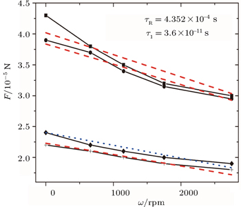
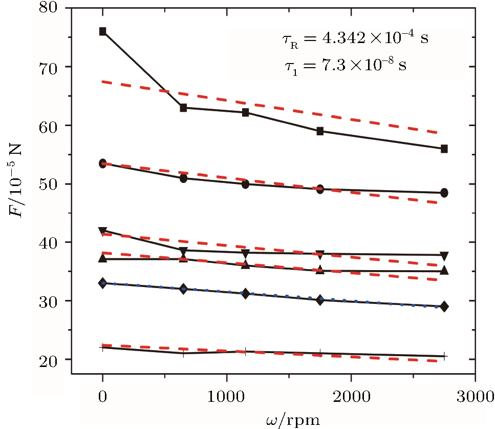
Fig. 2. Fitting of the experimental data of a rotating metallic particle (copper) and a stationary metallic one (copper) in an AC electric field with frequency ω0 = 300 Hz. The symbols denote the experimental data which are extracted from Ref. [36]. From upper to bottom: R = 19.314 mm (or gap = 0.254 mm) and E0 = 100 V/mm; R = 19.441 mm (or gap = 0.381 mm) and E0 = 100 V/mm; R = 19.314 mm (or gap = 0.254 mm) and E0 = 80 V/mm; R = 19.568 mm (or gap = 0.508 mm) and E0 = 100 V/mm; R = 19.441 mm (or gap = 0.381 mm) and E0 = 80 V/mm; R = 19.568 mm (or gap = 0.508 mm) and E0 = 80 V/mm. Similarly, according to our theory [Eq. (20)], the dotted line is plotted by choosing appropriate relaxation times, τR = 4.342 × 10⁻⁴ s and τI = 7.3 × 10⁻⁸ s, for the fitting of the case of R = 19.441 mm (or gap = 0.381 mm) and E0 = 80 V/mm. The two values, τR = 4.342 × 10⁻⁴ s and τI = 7.3 × 10⁻⁸ s, are then used for fitting the other five groups of the experimental data (dashed lines). In this figure, the unit of ω, “rpm”, stands for “rotations per minute”.
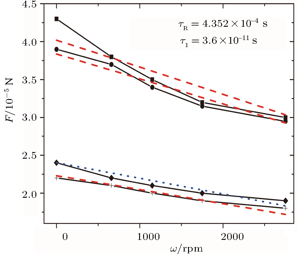
Fig. 3. Fitting of the experimental data of a rotating metallic particle (copper) and a stationary dielectric one (polyamide) in an AC electric field with frequency ω0 = 300 Hz. The symbols denote the experimental data which are extracted from Ref. [36]. From upper to bottom: R = 19.314 mm (or gap = 0.254 mm) and E0 = 100 V/mm; R = 19.441 mm (or gap = 0.381 mm) and E0 = 100 V/mm; R = 19.441 mm (or gap = 0.381 mm) and E0 = 80 V/mm; R = 19.568 mm (or gap = 0.508 mm) and E0 = 80 V/mm. According to our theory [Eq. (20)], the dotted line is plotted by choosing appropriate relaxation times, τR = 4.352 × 10⁻⁴ s and τI = 3.6 × 10⁻¹¹ s, for the fitting of the case of R = 19.441 mm (or gap = 0.381 mm) and E0 = 80 V/mm. The two relaxation times, τR = 4.352 × 10⁻⁴ s and τI = 3.6 × 10⁻¹¹ s, are then used for fitting the other three groups of the experimental data (dashed lines).

For the rotating metallic sphere, the well-known Maxwell–Wagner relaxation time[35,42] predicts , where εh (or σh) means the real part of the complex dielectric constant (or conductivity) of the host argon gas. According to the experiments by Tao and Lan,[36] we have and σh ≈ 0, thus yielding τMW = 1.22 × 10⁻¹⁸ s, which is much smaller than both of the above-mentioned fitting parameters, τR and τI. It is worth noting that charge imbalances could relax in a period of time, which is comparable to the characteristic collision time (τ′) of electrons in conductors,[43] . Here m, n, and e are the electron mass, average electron density, and electron charge, respectively. It is because the time dependence is so rapid that the inertia of electrons must be taken into account. For copper, one obtained τ′ ≈ 2 × 10⁻¹⁴ s.[43] In view of the precision of the experiments reported in Ref. [36], we expect that the collision time (τ′) should be comparable to the relaxation time τI. Then we can conclude that neither the collision process described by τ′ nor the leaky dielectrics process characterized by τMW[35,42] serves as the source of the relaxation time τR.

According to our results, the relaxation time τR is generally much longer than τI. In fact, the τR sources from polarized charges (described by ) under the local field of touching particles, as mentioned in Subsection 2.2. Because of the short separation between the particles, a strong local field is formed, and shifts the property of electrons in metallic particles. When a particle is rotating, the local field should change greatly.[37] Thus, the interaction force decreases.[36] In general, the change of local field of touching rotating metallic particles is likely to bring such a long relaxation time ∼ 10−4 s, due to the effect of multipolar interactions. As far as we know, theories of this process based on the first principles have not yet been found for predicting τR directly. In this situation, our method is a possible way to obtain τR of metallic particles by comparing with experiment data. On the other hand, the relaxation time τI, which originates from free charges (corresponding to ), is much shorter. The collision time as mentioned above can be used to understand the general vanishing value of τI. We can conclude that τI refers to the inertia of electrons in conductors. Since τR is much longer, we believe that the dielectric relaxation process plays a key role in the force reduction in the experiment.

4. Discussion and conclusion

When displaying the theoretical results in Figs. 2 and 3, we have assumed that the relaxation times of the touching rotating particle are unchanged, even if the separation between the two particles or the external electric field is changed. In fact, these factors also have an effect on the relaxation times, τR and τI. Therefore, we try to use Eq. (20) to fit the experimental data, by using more accurate relaxation times, as listed in Tables 1 and 2 explicitly. It is found that the relaxation times τR always take the values with the same order of magnitude for the current systems. The stability of the values of τR is an evidence of the validity of our fitting presented in Figs. 2 and 3. For the relaxation time τI ranges over several orders of magnitude, we think that either the limit of experimental precision or the inaccuracy of the fitting process is a possible reason. As mentioned above, the relaxation time τI is vanishing (compared with τR). Thus, tiny fluctuations of experimental data may lead to a great change of the fitting values of τI.

Table 1.

Relaxation times, τR and τI, for obtaining good fitting with experimental data of Fig. 2.

.
Table 2.

Relaxation times, τR and τI, for obtaining good fitting with experimental data of Fig. 3.

.

Here some comments are in order. Our method introduced the conductivity () to metallic particles. This can be understood from the charge conservation law

Here, the current can be written as Ohm’s law , while, according to the Maxwell equations, free charge . Such relations naturally give birth to Eq. (6), which contains both and .

To sum up, based on a first-principles approach, we have established an AC relaxation theory for dynamic metallic particles. An imaginary part has been introduced to the method established in Ref. [38] because the particle is conducting. The relaxation times were obtained according to the fitting with the experimental data. Good agreement between theory and experiment has shown that the relaxation processes of surface-polarized and free charges yield the reduction in the attracting interparticle forces between a rotating metallic particle and a stationary metallic or dielectric one. Our theory can help to determine the relaxation time of dynamic metallic particles in many fields.

Reference
1Tan PTian W JWu J YZhou L WHuang J P 2009 J. Phys. Chem. 113 9092
2Zhang L FHuang J P 2010 Chin. Phys. 19 024213
3Plachy TMrlik MKozakova ZSuly PSedlacik MPavlinek VKuritka I 2015 ACS Appl. Mat. Interfaces 7 3725
4Bai X KPu S LWang L WWang XYu G JJi H Z 2011 Chin. Phys. 20 107501
5He J NDing PWang J QFan C ZLiang E J 2015 Opt. Express 23 6083
6Felicia L JPhilip J 2015 Langmuir 31 3343
7Rabbani YAshtiani MHashemabadi S H 2015 Soft Matter 31 4453
8Fan C ZWang J QZhu S MHe J NDing PLiang E J 2013 J. Opt. 15 055103
9Han Q BYin CLi JTang Y BShan M LCao Z Q 2013 Chin. Phys. 22 094215
10Mestrom LLenders J J Mde Groot RHooghoudt TSommerdijk N A J MArtigas M V 2015 Nanotechnology 26 285602
11Kumar D TZhou Y LBrown VLu X YKale AYu L DXuan X C 2015 Microfluid Nanofluid 19 43
12Vyas N SLawrence K LGriffith J LHamzavi I H 2015 J. Cutan. Med. Surg. 19 488
13Tao RSun J M 1991 Phys. Rev. Lett. 67 398
14Halsey T C 1992 Science 258 761
15von Pfeil KGraham M DKlingenberg D JMorris J F 2002 Phys. Rev. Lett. 88 188301
16Wen WHuang XYang SLu KSheng P 2003 Nat. Mater. 2 727
17Tzima EIrani-Tehrani MKiosses W BDejana ESchultz D AEngelhardt BCao G YDeLisser HSchwartz M A 2005 Nature 437 426
18Misbah C 2006 Phys. Rev. Lett. 96 028104
19Martin SReichert MStark HGisler T 2006 Phys. Rev. Lett. 97 248301
20Xiao J JHuang J PYu K W 2008 J. Phys. Chem. 112 6767
21Wang LWang X QWang X GLiu Y 2014 Chin. Phys. 23 025203
22Liu HTong HXu N 2014 Chin. Phys. 23 116105
23Duits M H GGhosh SMugele F 2015 Langmuir 31 5689
24Fuhr GZimmermann UShirley S1996Electromanipulation of Cells259328259–328
25Becker F FWang X BHuang YPethig RVykoukal JGascoyne P R C 1995 Proc. Natl. Acad. Sci. USA 92 860
26Edwards BMayer T SBhiladvala R B 2006 Nano Lett. 6 626
27Yan Z JScherer N F 2013 J. Phys. Chem. Lett. 4 2937
28Chen KXiang NQuan Y LZhu X LSun D KYi HNi Z H 2014 Microfluid Nanofluid 16 237
29He J NWang J QDing PFan C ZLiang E J 2015 J. Opt. 17 055002
30Cebers A 2004 Phys. Rev. Lett. 92 034501
31Dávalos-Orozco L Adel Castillo L F 1996 J. Colloid Interface Sci. 178 69
32Fan G LJiang Y SLiu LLi F2010Acta Phys. Sin.595374(in Chinese)
33Teng L HWang XLai T S2011Acta Phys. Sin.60047201(in Chinese)
34Lin W ZShou QLiu L NWu YWen J HLai T S 2005 Chin. Phys. Lett 22 188
35Tian W JLiu M KHuang J P 2007 Phys. Rev. 75 021401
36Tao RLan Y C 2005 Phys. Rev. 72 041508
37Tan PTian W JZhou L WHuang J P 2009 J. Phys. Chem. 113 5412
38Gu G QYu K WHui P M 2002 J. Chem. Phys. 116 10989
39Jackson J D1999Classical Electrodynamics3rd edn.New YorkWiley
40Gu G QYu K W 2005 China Particuology 3 47
41Wen WMa HTam W YSheng P 1997 Phys. Rev. 55 R1294
42Russel W BSaville D ASchowalter W R1989Colloidal DispersionsCambridge, UKCambridge University Press
43Ashby N 1975 Am. J. Phys. 43 553