


Intense source of cold cesium atoms based on a two-dimensional magneto–optical trap with independent axial cooling and pushing
[Huang Jia-Qiang1, 3, Yan Xue-Shu2, 3, Wu Chen-Fei1, 3, Zhang Jian-Wei2, 3, Wang Li-Jun1, 2, 3, †,  ]
]
]
|
|


ߤ Corresponding author. E-mail:
Project supported by the National Natural Science Foundation of China (Grant No. 11304177).
We report our studies on an intense source of cold cesium atoms based on a two-dimensional (2D) magneto–optical trap (MOT) with independent axial cooling and pushing. The new-designed source, proposed as 2D-HP MOT, uses hollow laser beams for axial cooling and a thin pushing laser beam to extract a cold atomic beam. With the independent pushing beam, the atomic flux can be substantially optimized. The total atomic flux maximum obtained in the 2D-HP MOT is 4.02 × 10¹⁰ atoms/s, increased by 60 percent compared to the traditional 2D+ MOT in our experiment. Moreover, with the pushing power 10 μW and detuning 0Γ, the 2D-HP MOT can generate a rather intense atomic beam with the concomitant light shift suppressed by a factor of 20. The axial velocity distribution of the cold cesium beams centers at 6.8 m/s with an FMHW of about 2.8 m/s. The dependences of the atomic flux on the pushing power and detuning are studied in detail. The experimental results are in good agreement with the theoretical model.
Cold atomic beams have desirable features such as high flux at low mean velocity, narrow velocity distribution, and small divergence. They are widely used in fields of atom interferometry,[1–4] atomic clocks,[5–8] cold atom collisions,[9,10] and atom optics.[11] Besides, they are required for fast loading a magneto–optical trap (MOT) in an ultra high vacuum (UHV).[12]
The cold atomic beams can be produced by using a Zeeman slower[13] or an isotropic-light tube[14] to decelerate a thermal atomic beam along its propagation axis, or by extracting from a vapor MOT directly. Compared to the decelerator, the MOT source is preferred because of its narrower velocity distribution and higher brightness.[15] The MOT source can be implemented in various configurations, including the low-velocity intense source (LVIS),[16–18] the moving molasses (MM) MOT,[19] the pure two-dimensional (2D) MOT,[20] and the 2D+ MOT.[21]
The 2D+ MOT source is a configuration in which the two-dimensional magneto–optical trap is complemented with axial laser beams. With larger cooling volume and the capability of cooling or pushing in the axial direction, the 2D+ MOT can produce a higher atomic flux at a similar or even lesser power consumption than other configurations of the MOT source. For the axial laser beams, the configuration can be a pair of cooling beams (pushing and retarding beams),[21–24] one hollow beam,[25,26] or one pushing beam.[27–34] For the pair-of-beam configuration, the atoms are both cooled and pushed in the axial direction, which results in a high flux and a narrow axial-velocity distribution. Nevertheless, the laser power and detuning are mainly adapted to axial cooling rather than pushing. Considering the physical fact in the MOT, cooling decelerates atoms but pushing accelerates atoms. The pushing beam cannot be substantially optimized until its power and detuning is regulated independently. Besides, the axial laser light coming out along the cold atoms is rather intense, resulting in considerable light shift. For the one-hollow-beam configuration, the laser beam is far blue-detuned and shaped into a Laguerre–Gaussian donut mode. Cold atoms in the MOT can be channeled over a long distance with small divergence. Thus the atomic density is increased compared to that in a freely-propagating beam. In Carrat et al.’s recent study, the increase by a factor of 200 is achieved.[26] However, without axial cooling, the cold atoms from this kind of 2D+ MOT have undesired broad axial velocity distribution, tens of meters per second. For the one-pushing-beam configuration, the pushing beam can be a thin near-resonant beam,[27–32] or an intense far-detuned one.[33,34] These studies, especially the 2D2p MOT by Park et al.,[32] indicate that the pushing beam should have specific power and detuning. Though the pushing beam is optimized, without axial cooling, the efficiency of this kind of 2D+ MOT is lower than the first configuration.
In general, to obtain an intense cold atomic beam with narrow velocity distribution with the 2D+ MOT, the axial cooling and pushing is indispensable. Limited by the configurations above, the 2D+ MOT cannot be fully optimized. Besides, for experiments based on a cold atomic beam, such as atom interferometry and atomic clock, the problem of the light shift due to the pushing beam should also be resolved.[3,4] To substantially optimize the 2D+ MOT and significantly suppress the light shift, we propose a novel configuration for the axial laser beams. In the scheme, a pair of counter-propagating hollow laser beams are applied for axial molasses cooling. Another homocentric thin laser beam is used for pushing. The hollow beams and the pushing beam are functionally separated and do not interfere with each other. We propose “2D-HP MOT” to name this new scheme distinguishing it from the traditional 2D+ MOT, where H stands for the hollow cooling beams and P the thin pushing beam.
This paper is organized as follows. In Section 2, we explain the basic principle of the 2D-HP MOT, including the rate and trapping equation, the atomic flux analysis and the light shift effect. In Section 3, we present a detailed description of the experimental setup and the measurement of the cold atomic beam. The experimental results and discussions are arranged in Section 4. We summarize and give an outlook on future experiments in Section 5.
The flux of the cold atomic beam extracted from the 2D-HP MOT is determined by the rate equation, the relationship between the loading rate and the loss rates. The loading rate R indicates the capture capability of the MOT, which is derived from the flux through the surface of the cooling volume of atoms with a radial velocity below the capture velocity vr < vc.[20,21,35] Its definition per axial velocity interval [vz,vz + dvz] in cylindrical coordinate is[20]

The loss of the cold atoms within the MOT is mainly caused by three factors, which are the collisions between the cold atoms and the thermal background vapor (“cold–hot” collisions), the collisions between two cold atoms (“cold–cold” collisions), and the outcoupling from the cold atomic cloud into the beam, respectively. The loss rate due to the “cold–hot” collisions is proportional to the density of the thermal background vapor, which can be written as Γtrap = nσvrms.[35] Here vrms is the root-mean-square (rms) velocity of thermal atoms, and σ is the effective collision cross section. For a cesium atom, σ is 2 × 10⁻¹³ cm2. The loss rate caused by the “cold–cold” collisions is βNN/V, growing as the density of the trapped cold atoms. Here βN is the trap-loss parameter, which contains the probabilities for inelastic processes, such as fine-structure-changing collisions, radiative escape, and photoassociation. The study on βN has been an interesting and important topic. Both theoretical and experimental works verify that βN increases linearly with the MOT laser intensity.[9,36,37] The loss rate due to the outcoupling is called the outcoupling rate Γout, which represents the capability of the pushing laser beam extracting the cold atomic beam from the MOT. It can be simply written as Γout = 1/tout, where tout is the time for pushing the cold atoms out of the MOT.[21]
In the 2D-HP MOT, the time tout is determined by the cold atom velocity and the distance d that atoms travel out of the MOT. Under the radiation pressure from the pushing laser beam, the velocity is affected by the power and detuning and varies as


In addition to the three loss rates above, the heating effect due to the pushing laser beam also results in the loss of cold atoms. Obviously, this loss rate is related to the intensity and detuning of the pushing laser, and we assumed it can be expressed as Γheat ∼ αI · s′, where α is a coefficient, I is the pushing laser intensity, and s′ = s/(1 + s + 4(δ − kv − δheat)2/Γ2). The parameter δheat corresponds to the most effective heating detuning.
At the balance of loading and loss, the rate equation of the 2D-HP MOT can be written as[20,21]


According to Eq. (
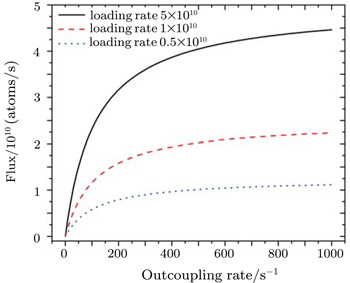
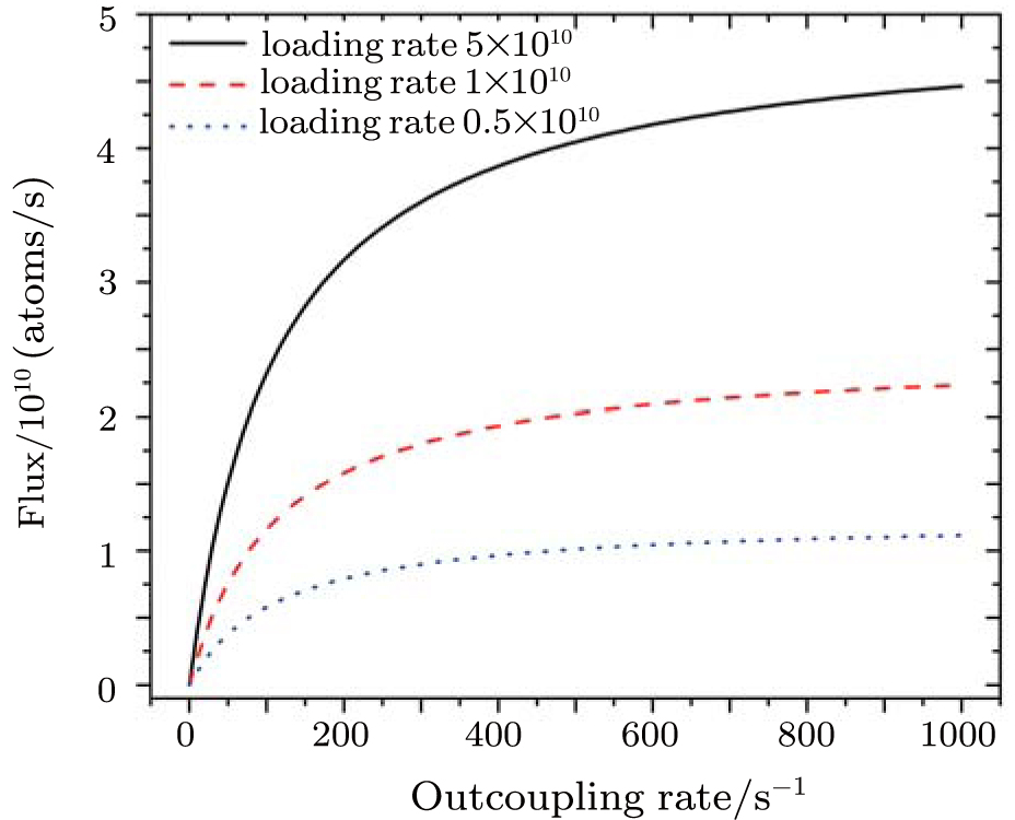 | Fig. 1. The dependence of the total atomic flux on the outcoupling rate at different loading rates: 5 × 10¹⁰ atoms/s (black solid line), 1 × 10¹⁰ atoms/s (red dashed line), and 5 × 10⁹ atoms/s (blue dotted line). |
With trapping and sub-Doppler cooling, the velocity of the cold atoms in the MOT is close to zero value and follows a rather narrow Maxwell distribution.[21] Taking the average distance as d = L/2 = 20 mm and the initial axial velocity vz(0) = 0, the outcoupling rate Γout to different pushing power (beam diameter = 3 mm) and detuning can be calculated with Eq. (
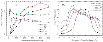
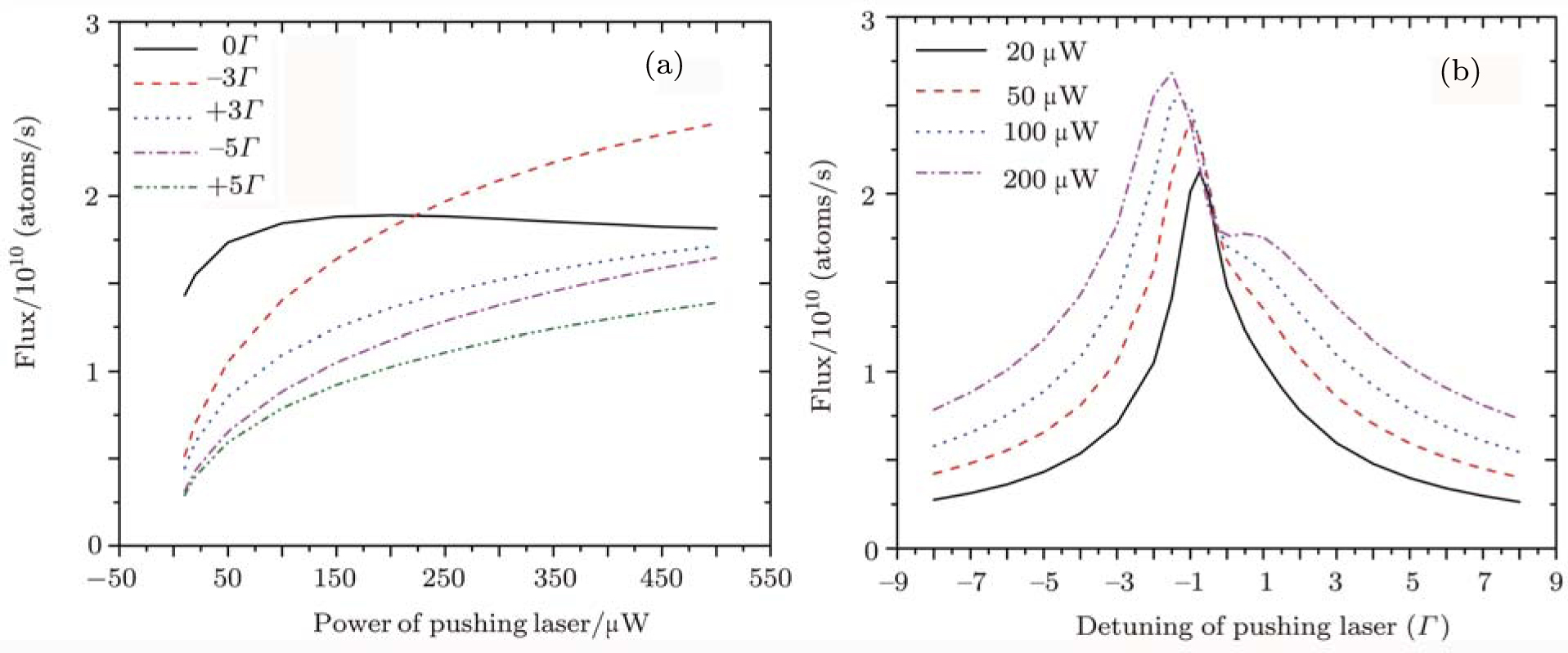 | Fig. 2. The calculated atomic flux of the zero-velocity atoms: (a) the flux varying with the pushing power of various detunings, 0Γ (black solid line), −3Γ (red dashed line), +3Γ (blue dotted line), −5Γ (magenta dashed-dotted line), and +5Γ (green dash-dot-dot line); (b) the flux varying with the pushing detuning of various power, 20 μW (black solid line), 50 μW (red dashed line), 100 μW (blue dotted line), and 200 μW (magenta dashed-dotted line). |
In addition to the independently-optimized atomic flux, the light shift is another main concern of the 2D-HP MOT. The light shift ΔωF to the cesium atom is[38]

The experimental setup consists of the vacuum system, the quadrupole magnetic field, and the laser system. The cesium vapor cell is formed by a 55-mm diameter, long circular quartz tube. Both ends of the tube are connected to the pump system. Near the detection region, an ion pump is added to keep a higher vacuum. A temperature-controlled cesium reservoir is connected to the tube beside the MOT via a vacuum valve. In the experiments, the vacuum is 1.2 × 10⁻⁵ Pa at the MOT, and 3.5 × 10⁻⁶ Pa at the detection region.
The quadrupole magnetic field is generated by two orthogonal pairs of 140 × 100-mm rectangular coils, as shown in Fig.
 | Fig. 3. The schematic diagram of the 2D-HP MOT. M1, M2: mirror; λ/4, λ/2: wave plate; PBS: polarized beam splitter; HR-coated λ/4: λ/4 wave plate coated with high-reflectivity film; σ+, σ−: circular polarization; Ω: collection angle; PD: photodiode. |
The diode laser system includes a DBR laser, a DFB laser and an extended cavity diode laser (ECDL), which are all frequency-locked using the standard saturation absorption (SA) techniques. The DBR laser beam is split into two parts: one major part is used for the cooling and the other part is used as the pushing beam. The cooling frequency is detuned −2.5Γ from the cycling transition


The configurations of the laser beams are presented in Fig.
The plug laser and the probe laser are used for diagnosing the cold atomic beam. The plug laser is 2.5 mW with a 5-mm diameter, and the probe laser is a 200-μW rectangular beam (15 mm × 2 mm). The probe laser beam and plug laser beam are separated by 300 mm. To enhance the fluorescence signal, the probe laser beam is retro-reflected. The fluorescence emitted from the cold cesium atoms is collected by the lens assembly with a spatial angle Ω, and measured by a photodiode (Hamamatsu S3204-08). A time-of-flight (TOF) method is used to measure the atomic beam flux and the axial velocity distribution. Suddenly opening the plug beam, the cold atoms would be pushed away from the axis. The time dependence of the decaying fluorescence signal S(τ) is detected. Then the axial velocity distribution Φ(vz) can be deduced as

In experiments, the 2D-HP MOT is realized, where the axial cooling and pushing are accomplished by a hollow beam and another pushing beam, respectively. The dependences of the total atomic flux on the pushing power and detuning are measured, and a comparison is made between the 2D-HP MOT and the traditional 2D+ MOT based on the experimental results.
In the 2D-HP MOT, the hollow beam keeps the loading rate but makes no contribution to the atomic beam extraction, and the pushing beam regulating the outcoupling rate determines the atomic beam extraction. In experiment, the pushing beam is 15 μW and resonant with the 4 → 5′ cycling transition. By sweeping the probe laser frequency around the 4 → 5′ cycling transition, the hyperfine spectral lines of the cold atomic beam in different conditions are measured as shown in Fig.
 | Fig. 4. Signal of the cold cesium atomic beam in different conditions: (a) the 4 − 5′ hyperfine spectral lines: both hollow and pushing beams on (black solid line), only pushing beam on (red dashed line), only hollow beam on (blue dotted line); (b) the axial velocity distribution: only pushing beam on (red dashed line), both hollow and pushing beam on (black solid line). |
Besides, the axial velocity distribution in the pushing-only condition and the cooling-pushing condition is measured, as shown in Fig.
These results demonstrate that the 2D-HP MOT works as designed. The hollow beam keeps the loading rate and the pushing beam determines the outcoupling rate. An intense cold atomic beam is extracted when both laser beams are on.
In experiments, the dependence of the total atomic flux on the pushing power is measured at the detuning of −7Γ, −5Γ, 0Γ, +5Γ, and +7Γ, as shown in Fig.
 | Fig. 5. The dependences of the total atomic flux on the pushing parameters: (a) the dependence on the pushing power at different pushing detuning:−7Γ (black square line), −5Γ (red circle line), 0Γ (green diamond line), +5Γ (blue up triangle line), and +7Γ (magenta down triangle line); (b) the dependence on the pushing detuning at different pushing power: 20 μW (black square line), 60 μW (red circle line), 100 μW (blue up triangle line), and 150 μW (magenta down triangle line). |
Besides the 0Γ condition, the experimental results of +5Γ and +7Γ in Fig.
As discussed in Section 2, the heating effect caused by the pushing laser around the axis accounts for the flux loss. The heated atoms will escape from the MOT, rather than being pushed out, if its velocity is faster than the capture velocity. In experiments, the section of the pushing laser beam is a little larger than the aperture, which can generate a more serious heating effect when the pushing laser is suitably blue-detuned.
Additionally, the dependence of the total atomic flux on the pushing detuning at pushing power of 20 μW, 60 μW, 100 μW, and 150 μW are measured as shown in Fig.
To compare to the traditional 2D+ MOT with a pair of cooling beams, the 2D-HP MOT is modified by blocking the pushing beam and replacing the hollow laser beam by a regular Gaussian beam. The laser beam has the same diameter, power, and detuning as the previous hollow beam. The central intensity of the Gaussian beam is the pushing intensity, 8.06 mW/cm2. Other parts of the setup in Fig.
The axial velocity distribution of the cold atomic beam extracted from the 2D+ MOT centers at 7.2 m/s with an FWHM of 3.2 m/s, the black solid line shown in Fig.
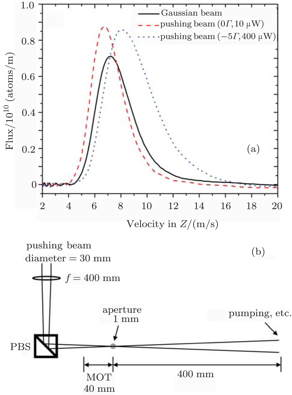 | Fig. 6. (a) The axial velocity distributions of the cold atomic beams: 2D+ MOT (regular Gaussian beam, black solid line), 2D-HP MOT (0Γ, 10 μW, red dashed line), and 2D-HP MOT (-5Γ, 400 μW, blue dotted line). (b) Schematic diagram of the pushing beam expander. |
To make a comparison with the 2D+ MOT, the velocity distributions obtained in the 2D-HP MOT with the pushing parameters (−5Γ, 400 μW) and (0Γ, 10 μW) are plotted in Fig.
For the parameters (0Γ, 10 μW), the pushing laser intensity is 0.14 mW/cm2. In this condition, the velocity distributes around 6.8 m/s with an FWHM of 2.8 m/s (the red dashed line shown in Fig.
Furthermore, with a minor adjustment to the thin pushing beam like those in Refs. [26] and [29], the light shift can be further suppressed. As shown in Fig.
In this work, we present a new design for a source of cold cesium atoms, the 2D-HP MOT. With independent axial cooling and pushing, the 2D-HP MOT can substantially optimize the atomic flux. The atomic flux maximum obtained in the 2D-HP MOT is 4.02 × 10¹⁰ atoms/s, 60% higher than the traditional 2D+ MOT. With proper pushing parameters, the 2D-HP MOT can generate a rather intense cold atomic beam with the concomitant light shift 20 times smaller than that in the traditional 2D+ MOT. Compared to the traditional 2D+ MOT, the 2D-HP MOT needs some more facilities to provide the hollow beam and the pushing beam. But with the total atomic flux increased and the light shift suppressed, it can help improve the precision measurement experiments on cold atomic beams, for example, an atomic clock based on a continuous cold cesium atomic beam.
| 1 | |
| 2 | |
| 3 | |
| 4 | |
| 5 | |
| 6 | |
| 7 | |
| 8 | |
| 9 | |
| 10 | |
| 11 | |
| 12 | |
| 13 | |
| 14 | |
| 15 | |
| 16 | |
| 17 | |
| 18 | |
| 19 | |
| 20 | |
| 21 | |
| 22 | |
| 23 | |
| 24 | |
| 25 | |
| 26 | |
| 27 | |
| 28 | |
| 29 | |
| 30 | |
| 31 | |
| 32 | |
| 33 | |
| 34 | |
| 35 | |
| 36 | |
| 37 | |
| 38 | |
| 39 |