

Two-color light-emitting diodes with polarization-sensitive high extraction efficiency based on graphene
[Sattarian H1, †,  , Shojaei S2, Darabi E1]
, Shojaei S2, Darabi E1]
|
|


† Corresponding author. E-mail:
In the present study, graphene photonic crystals are employed to enhance the light extraction efficiency (LEE) of two-color, red and blue, light-emitting diode (LED). The transmission characteristics of one-dimensional (1D) Fibonacci graphene photonic crystal LED (FGPC-LED) are investigated by using the transfer matrix method and the scaling study is presented. We analyzed the influence of period, thickness, and permittivity in the structure to enhance the LEE. The transmission spectrum of 1D FGPC has been optimized in detail. In addition, the effects of the angle of incidence and the state of polarization are investigated. As the main result, we found the optimum values of relevant parameters to enhance the extraction of red and blue light from an LED as well as provide perfect omnidirectional and high peak transmission filters for the TE and TM modes.
Light-emitting diodes (LEDs) are small new-type low power, long lifetime, and convenient light sources that are used in backlight lighting of liquid crystal displays, automotive lighting, sign illuminations, and vehicle and traffic signals. For these and other advanced applications, LEDs with higher light output at lower power consumption are needed.[1] A source of white light needs LEDs that deliver red, green, and blue light. The first red LED was created in the 1950s and researchers then managed to create devices emitting light at shorter wavelengths, reaching green by the 1960s. However, researchers struggled to create blue light. The Nobel Prize in Physics 2014 was awarded jointly to Isamu Akasaki, Hiroshi Amano, and Shuji Nakamura “for the invention of efficient blue LEDs which has enabled bright and energy-saving white light sources”.[2,3]
However, there is a problem in LED technology development denoting that the refractive index between air and the materials is large, resulting in the light produced by the active area having total internal reflection at the interface of materials with different refractive indexes, and not being extracted. Then the efficiency of these devices is limited due to the total internal reflection in the active region (e.g., semiconductor) interface and the outer medium. The critical angle of the total internal reflection is low (e.g., 18.4° for GaAs and 23° for GaN), so only a small fraction of light generated in the active region of the LED can escape into the outer environment. The light extraction efficiency (LEE) at the active region/air single interface is about ∼ 1/4n2.[4] Therefore, the external quantum efficiency of LEDs is poor even when the internal quantum efficiency is close to unity.
To avoid the above structural problem of LEDs and to extract more light from them, researchers have suggested several approaches, such as changing the LED chip shape,[5] nanohybrid structures,[6–8] micro-rods,[9] developed electron blocking layer structure,[10] photon recycling,[11] coupling to surface plasmonic modes,[12] roughening the surface[13,14] and metallic photonic crystal embedding in LED.[15] These approaches, however, do not alter directly the spontaneous emission properties of the devices. While, roughened surface, is an inexpensive to increase the light extraction efficiency, its morphology is irregular and uncontrolled. Recently, an approach using photonic crystals (PCs) was adopted and the LEE was enhanced dramatically. In this method, a two-dimensional (2D) PC is prepared in an LED surface in order to improve the LEE of LED surface using different periods of PC structures patterned in the surface.[16] The aim of this method is to avoid total internal reflection and to prevent lateral propagation of the light-waveguide effect and to enhance light extraction efficiency. The existence of a photonic band gap in a PC at the light emission wavelengths of LED modifies the guiding properties and reduces the waves propagating in lateral directions relative to the LED axis.[17] The enhancement of LEE in PC-LED occurs through a combination of spontaneous emission enhancement from a photonic crystal effect and Bragg scattering, which reduces parasitic absorption.[18]
Graphene, as a kind of gapless two-dimensional semiconductor, has attracted significant attention in recent years owing to its abundant potential application in nanoelectronic devices and optoelectronic devices. Due to the unique and extraordinary properties including high mobility of carriers, flexibility, robustness, environmental stability,[19,22] electronic energy spectrum without a gap between the conduction and valence bands, and frequency independent absorption of electromagnetic radiation, graphene has been the object of many recent experimental and theoretical studies in photonics.[23] This property makes graphene a suitable option for optoelectronic devices such as transparent electrodes, designing photonic devices, and optical display materials.[24,25] Recently, it has been shown that graphene can be used in tunable terahertz devices.[26,27] Improvement of the sensitivity of localized surface plasmon resonance (SPR) sensors by graphene was also reported.[28] One-dimensional graphene-based photonic crystals (1D-GPC), in which the graphene sheets are embedded between adjacent layers as a new type of transmission filter, attract considerable interest.[29]
Considering the benefits of using PCs as well as graphene, the present study attempts to explore how to enhance the LEE by considering the photonic band structure of one-dimensional Fibonacci quasi-periodic graphene photonic crystal (1D-FGPC). To reach this goal, we adopt the transfer matrix method to study the propagation of light through 1D-FGPC by using the optical conductivity of graphene.[30] Then, we theoretically introduce the optimized 1D-FGPC hybrid structure to design the high extracted red and blue LEDs.
According to the definition of light extraction efficiency ηextr of light emission from an LED, we have

We will find that the optimization of the transmission spectrum of 1D-FGPC enhances the LEE of LED.
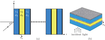
In this work, one-dimensional 3rd-order Fibonacci quasi-periodic graphene photonic crystal is used to design the two-color transmission filters. The 1D-FGPC model is shown in Fig. 

 | Fig. 1. (a) Structure of the 3rd-order 1D-FGPC. (b) Schematic diagram of unit cell for 1D-FGPC. The graphene monolayers are embedded between dielectric layers. |
With the propagation of light across an interface formed by a graphene layer which separates two dielectrics, there will be surface current in the graphene layer. The surface current density J of the graphene layer can be obtained from Ohm’s law, namely, Jx = σEx for TM waves and Jy = σEy for TE waves. According to the expressions of electric and magnetic fields, the boundary conditions and the propagation matrix of light in a homogenous medium, we obtain the transfer matrix Mj(dj,ω) (j = A,B) of a dielectric layer and a graphene sheet for TE and TM waves as[29]


In this section, we choose the optimum values of optical and geometrical parameters (dA, dB, εA, εB) of the system for red and blue light frequencies (about 440 THz and 630 THz, respectively). To find optimized parameters, in Fig.
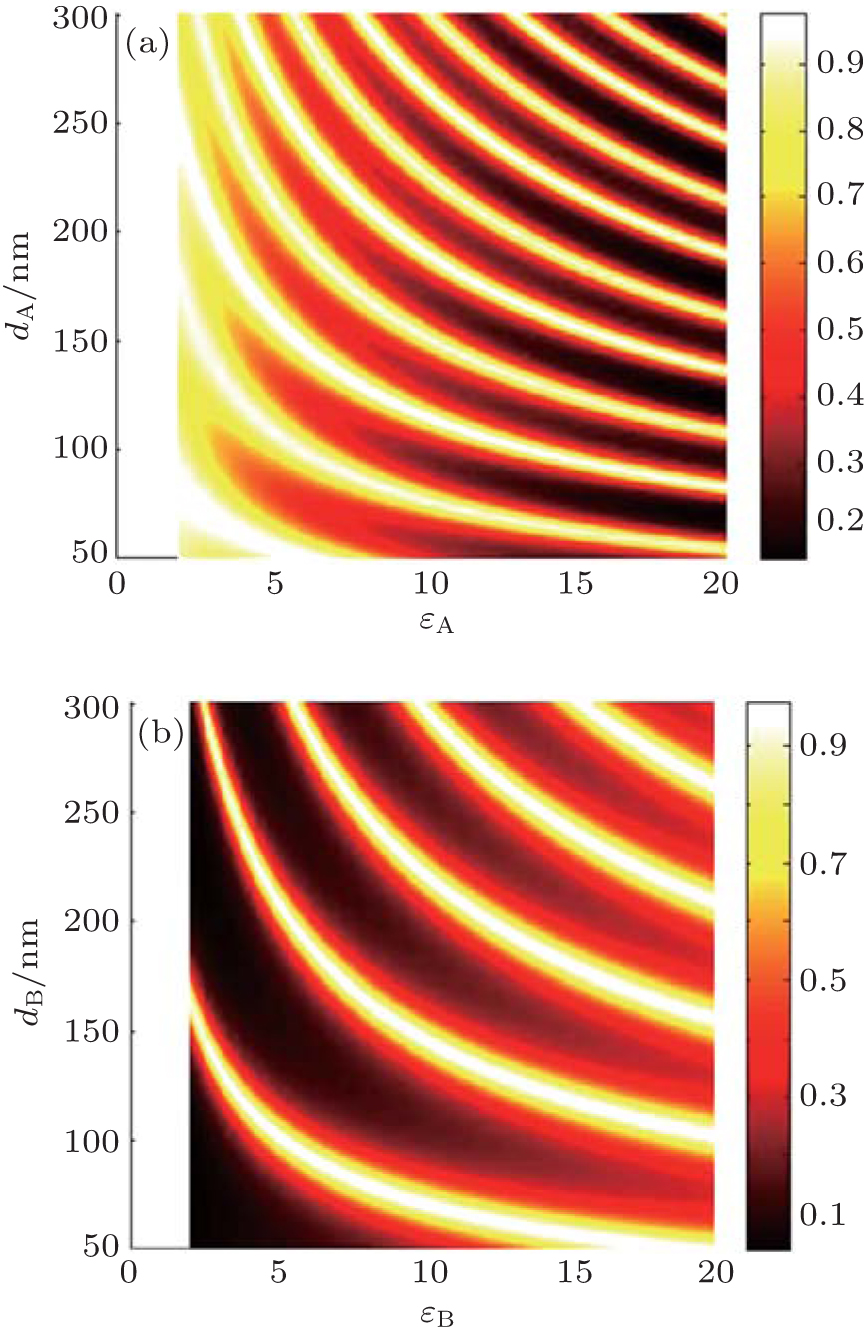 | Fig. 2. Contour plots of the transmission spectrum of the 1D-FGPC (T3) structure as a function of the permittivities and thicknesses in the case of σg ≠ 0 and blue light frequency for the dielectric material A (a) and the dielectric material B (b). The waves are normal incidence to the interfaces and temperature and chemical potential are chosen as T = 300 K and μC = 0.2 eV. |
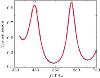
Our calculations show that for higher-order Fibonacci quasi-periodic 1D-GPC (4th, …) transmission spectrum will be decreased. Therefore, we focused on the 3rd-order Fibonacci quasi-periodic graphene photonic crystal of 1 period. Figure
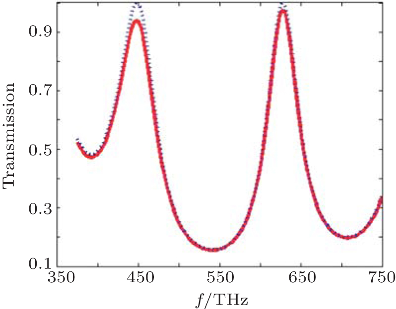 | Fig. 3. The transmission spectrum of 1D-FGPC (T3) structure as a function of the light frequency in the cases of (a) σg ≠ 0 (solid red curve) and (b) σg = 0 (dotted blue curve) for the normal incidence of the waves. Temperature and chemical potential are chosen as T = 300 K and μC = 0.2 eV. |
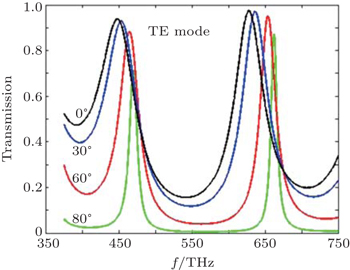
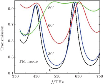
For oblique incidence (θ ≠ 0°), transmission spectrum of 1D FGPC (T3) structure is calculated with graphene sheets as a function of the light frequency for different incident angles plotted in Figs.
 | Fig. 4. Transmission spectrum of 1DGPC (T3) structure in the case of σg ≠ 0 as a function of the light frequency for different incident angles in the TE mode: θ = 0° (black curve), θ = 30° (blue curve), θ = 60° (red curve), and θ = 80°(green curve). |
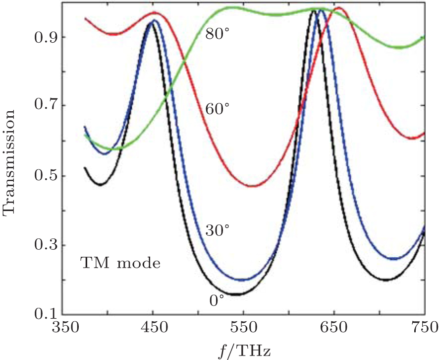 | Fig. 5. Transmission spectrum of 1DGPC (T3) structure in the case of σg ≠ 0 as a function of the light frequency for different incident angles in the TM mode: θ = 0° (black curve), θ = 30° (blue curve), θ = 60° (red curve), and θ = 80° (green curve). |
The findings demonstrate that our model structure is suitable for enhancing the mono-color light extraction efficiency of TE mode in (red or blue) LEDs. In addition, in the case of TM mode, it is useful to enhance the LEE in a wide range of visual frequencies.
To find out more, we consider the dependence of photonic band gap (PBG) on the incidence angle with graphene as a function of the light frequency and the incident angle. The results are displayed in Fig.
 | Fig. 6. Contour plots of the transmission spectrum of the 1D-FGPC (T3) structure as a function of the light frequency and the incident angle with graphene sheets for TE waves (a) and TM waves (b). |
In conclusion, we employed the proposed 1D-FGPC hybrid structure and optimized relevant parameters for the red–blue LEDs with the transfer matrix method. An optimized structure in terms of thickness, number of periods, layers, refractive indices, and permittivity of materials has been obtained. The 1D-FGPC filters with high transmission rates of 93.8 percent and 97.38 percent are located in the red and blue light frequencies (448.2 THz and 628.1 THz, respectively) for the normal incidence of the waves. The new graphene-photonic heterostructure provides perfect omnidirectional and high peak transmission filters for the TE and TM modes. This Fibonacci structure provides potentiality for fabricating red–blue two-color filters in the visible band and also for enhancing the extraction of red–blue light from an LED.
| 1 | |
| 2 | |
| 3 | |
| 4 | |
| 5 | |
| 6 | |
| 7 | |
| 8 | |
| 9 | |
| 10 | |
| 11 | |
| 12 | |
| 13 | |
| 14 | |
| 15 | |
| 16 | |
| 17 | |
| 18 | |
| 19 | |
| 20 | |
| 21 | |
| 22 | |
| 23 | |
| 24 | |
| 25 | |
| 26 | |
| 27 | |
| 28 | |
| 29 | |
| 30 | |
| 31 | |
| 32 | |
| 33 | |
| 34 | |
| 35 |