1. IntroductionAs artificial atoms, superconducting qubits are considered as one of the most promising approaches to realize quantum computing.[1–4] In order to realize practical quantum computing, a long energy relaxation time (T1) is required. Recent studies found that the energy losses, including surface losses,[5] dielectric losses,[6] and quasiparticle losses,[7,8] will induce the energy relaxation in superconducting qubits. The surface losses and dielectric losses can be optimized by improving the qubit design and fabrication. Since superconducting qubits work at about 20 mK, which is far below the temperature corresponding to the superconducting energy gap Δ, the equilibrium quasiparticles in the superconducting circuits tend to vanish.[9] Therefore, the quasiparticle losses mainly come from the non-equilibrium quasiparticles excited from the infrared radiation (IR) of environment.[10] Moreover, the recombination of these non-equilibrium quasiparticles is slow.[11]
In experiments, qubits are usually covered by a metal sample box. However, IR can still enter the sample box through the control coaxial cables, connectors, and the lid joint then generates quasiparticles. The total number of quasiparticles can be calculated by the rate equation[11]

where
P is the absorbed light power of the photons with the energy larger than 2
Δ,
G is the thermal generation term caused by phonons, and
R is a constant which describes the quasiparticle recombination. For a general qubit measurement setup, the sample box is mounted on the mixing chamber stage (20 mK) of a dilution refrigerator and the environment is a 700 mK shield thermally anchored on the still plate. Therefore, the light-induced density largely exceeds the thermal background. Neglecting the thermal generation term, we obtain that the density of the non-equilibrium quasiparticles scales as

.
[9] Now we approximately treat IR as the ideal black body radiation and estimate the absorbed light power. Since the radiation power per volume at frequency
ν is

we can get the total black body radiation power by integration:
∫ Ubdd
ν. Due to the fact that the generally used aluminum qubits have a superconducting energy gap 2 × 44 GHz, the absorbed photons with frequency larger than 88 GHz will contribute to the quasiparticle excitation. We can then get the absorbed light power by integrating Eq. (
2) from 88 GHz to infinity. For IR from 700 mK shield, the absorption is about 10% of the total black body radiation power. For IR from unfiltered control and measurement coaxial cables, the environment temperature corresponds to the temperature of the second pulse tube stage of the refrigerator or the effective temperature of the high electron mobility transistor (HEMT) amplifiers, which is larger than 3 K. Then the absorbtion is larger than 92% of the total black body radiation power.
In order to suppress IR from 700 mK shield and coaxial cables, different kinds of shields and filters have been designed. The materials generally used are energy lossy powders[9,12] (copper, stainless steel, and carborundum) and Eccosorb[13,14] (CR-110, CR-124, FGM-40, and GDS from Emerson&Cuming), respectively. However, most of these materials are magnetically loaded and will cause magnetic fluctuations at low temperature. Since superconducting qubits are very sensitive to magnetic noise, it is better to find nonmagnitic material to improve the qubit performance.
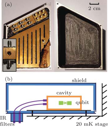
In this paper, we present a kind of nonmagnetic infrared filter and shield for superconducting qubits. We use a nonmagnetic epoxy which can block infrared photons. The filter is coaxial with Stycast 2850FT as the dielectric. The shield is made of aluminum with Stycast 2850FT and carborundum powders coating on the wall. We use a three-dimensional (3D) transmon to test the effect of the filters and the shield. The energy relaxation time of the transmon increases remarkably.
2. Design and fabrication2.1. Infrared filterIn superconducting quantum computing, microwave coaxial cables are used to transmit microwave fields to control and measure the qubits. The insert loss of these microwave cables increases with frequency in the microwave region then gradually decrease in the infrared region. External noise can go down along the cables to the qubits. Therefore these cables have to be carefully filtered to protect qubits from noise. In general, commercial microwave filters are used to absorb external noise while allowing a signal to pass through. Unfortunately, most of these microwave filters cannot filter infrared light since IR frequency is much higher than microwave frequency.[15] Therefore, we need to fabricate suitable infrared filters.
There are two important issues for designing an infrared filter. One is the geometric size to satisfy the requirement of the impedance matching with microwave devices. The other is selecting the correct filling materials to attenuate IR. In our design, we choose a black color epoxy, Stycast 2850FT from Emerson&Cuming, which is a kind of nonmagnetic material. In order to realize the 50 Ω impedance, we perform the impedance calculation firstly. For simplicity, a coaxial geometry is chosen. For a coaxial cable of inner radius a and outer radius b with dielectric in between, the impedance is[16]
where
μ0 and
ε0 are the permeability and permittivity in a vacuum, and
μr and
εr are the relative permeability and permittivity. In our design, we use the SMA-KFD267-H connector whose radius of the pin is
a = 0.80 mm. From the data sheet, we get the parameters of Stycast 2850FT:
εr = 5.36,
μr = 1.00. Therefore, we obtain the outer radius of the coaxial filter is
b = 5.20 mm. Since Stycast 2850FT almost has zero attenuation in microwave frequency, the length of the filter is not crucial. We choose the length as 15.00 mm. To fabricate the filters, we machine 3 holes for each filter on an oxygen free copper block. Two 5.20 mm holes are on each side to mount SMA connectors. One 2.00 mm hole locates in the center of the filter to fill the Stycast 2850FT. At first, the center pins of two SMA connectors are soldered together through the inject hole. After mixing Stycast 2850FT with Catalyst 9, we place the mixture into a vacuum chamber to degas. Then, the mixture is injected into the filter through the inject hole carefully. After 24 h curing, we remove the additional Stycast 2850FT by fine abrasive paper.
Because the filter is relatively small, we can integrate 12 filters together in each copper block. Among them, 6 filters are impedance matched, as described before. The other 6 filters are used for direct-current (DC) lines. Therefore, they are designed to mismatch 50 Ω impedance purposely. We use SMA-KYD47 connectors whose radius of pins is 1.27 mm.
2.2. Infrared shieldThe infrared shield is designed to prevent the sample from IR coming from the still shield (700 mK) of the dilution refrigerator. We made the shield with an aluminum box surrounding the qubit sample box. The shield box is composed of two pieces, a plate and a cover. Since at low temperature aluminum is a thermal insulator, two oxygen free copper blocks are designed for thermal anchor. One is mounted inside the shield box, and the other is mounted outside the aluminum plate. They are connected by a copper tape. The copper block outside the shield is thermally anchored to the mixing chamber of the dilution refrigerator (Fig. 1). Therefore, the sample box that mounted on the copper block inside the plate can be cooled down to base temperature.
We mount the infrared filters inside the shield and then use the Stycast 2850FT to seal the seam. In addition, to further prevent IR from reaching the sample box, we spread a kind of home made IR photon absorbing material on the inside wall of the shield. The material is combined with Stycast 2850FT and carborundum in a ratio of 60% to 40% by volume. The carborundum powders have 6 different sizes with 60, 300, 400, 800, 1300, and 3000 mesh, respectively. The ratio of them is almost the same by volume. We mix all the carborundum powders with Stycast 2850FT, and spread the mixture inside the shield. After curing, the mixture is very rough and hard. Even if some infrared photons leak into the shield, they will be quickly absorbed by the material.
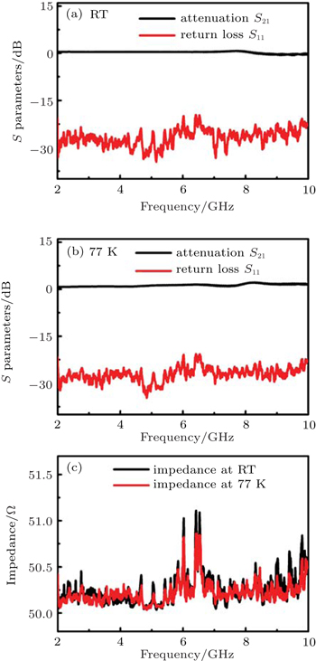
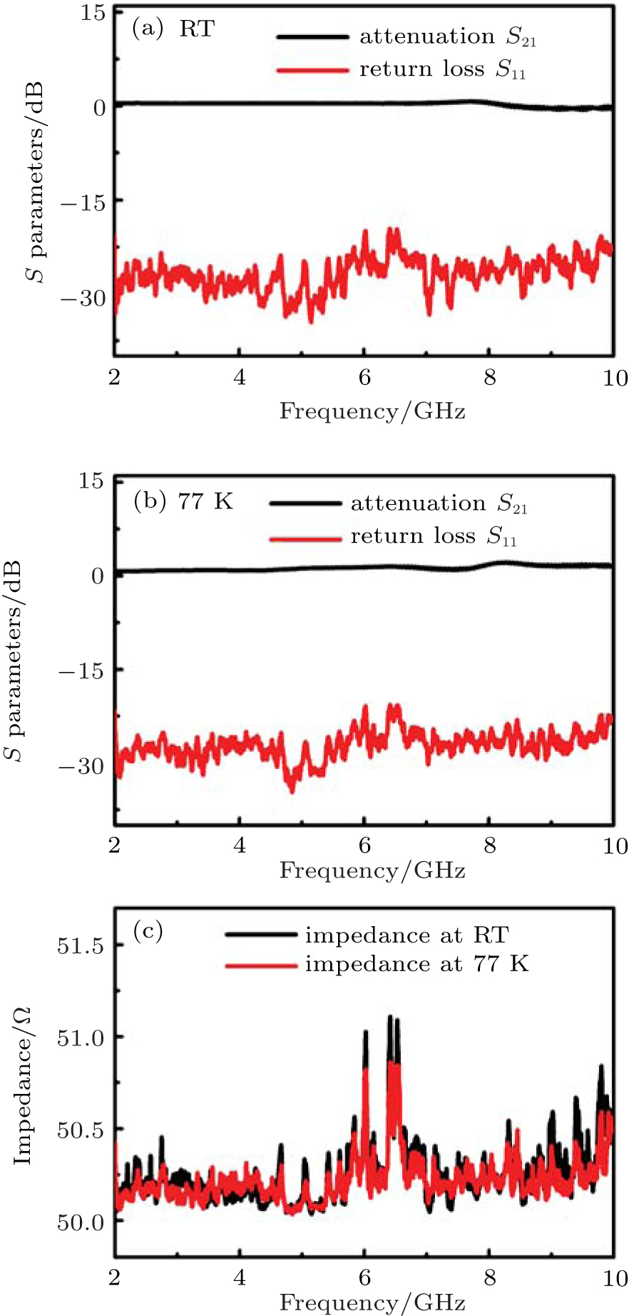
3. Results and discussion3.1. Filter characterizationWe measure the attenuation (S21) and return loss (S11) of the filter at room temperature (RT) and 77 K by a network analyzer from 2 GHz to 10 GHz. The attenuation and the return loss are defined as S21 = 10lg (P2trans)/(P1in) and S11 = 10lg (P1ref)/(P1in), where P1in is the microwave power incident on the input of the filter, P1ref is the microwave power that is reflected off to the input of the filter, and P2trans is the transmitted microwave power to output of the filter. For testing at 77 K, the filter is immersed in liquid nitrogen. Figures 2(a) and 2(b) show the attenuation and the return loss of the filter at different frequencies from 2 GHz to 10 GHz.
From the return loss, we can calculate the impedances of the filter at different frequencies by[16]

where
Γ is the reflected coefficient, and
Z0 = 50 Ω is the characteristic impedance of the cable. The relations between
Γ and
S11 are:
S11 = 10lg
Γ. Figure
2(c) shows the impedance of the filter as a function of frequency. The
S parameters and the impedances indicate that the filters perform excellently in the relevant frequency region.
3.2. Qubit energy relaxation measurementIn order to test the effect of our filter and shield, we measure the energy relaxation time of a 3D transmon. The cavity is made of copper with the resonance frequency of the TE101 mode 8.6814 GHz. The transmon is fabricated on an oxide silicon substrate. It is composed of a single Josephson junction and two pads (250 μm × 500 μm), which are patterned using standard e-beam lithography, followed by double-angle shadow evaporation of aluminium. The thicknesses of the aluminium film are 30 nm and 80 nm, respectively. Then the lift-off is conducted to form the final structure. The chip is diced into 3.00 mm × 6.80 mm size to fit into the 3D rectangular cavity.
In order to do a comparison test and check whether the shield and filters can improve the qubit’s energy relaxation time, the same sample is cooled down to 20 mK in a dilution refrigerator twice. The first time, the sample is mounted in the shield with filters, and the second time, the shield and filters are removed.
The measurement system is ordinary microwave heterodyne,[17] and the readout is performed with the so-called “high power readout” scheme.[18] By sending in a strong power microwave on-resonance with the cavity, we acquire the transmitted amplitude of the microwave, which reflects the state of the transmon due to the non-linearity of the cavity quantum electrodynamics (c-QED) system.[19,20]
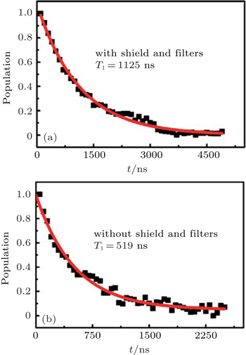
In both experiments, we first measure the saturation spectroscopy. We use a low power continuous microwave with different frequencies to irradiate the transmon, and we find that the transition frequency of the ground state to the first excited state is ω01 = 2π × 5.9601 GHz. Then, at the transition frequency, we excite the transmon from the ground state to the first excited state. After a period of time, the population in the first excited state is measured. By varying the waiting time t, we obtain the qubit population in the excited state as a function of t (see Fig. 3). Finally, by fitting the population versus t to an exponential decay, Pe = exp (−t/T1), we obtain the energy relaxation time T1. For the measurement with the shield and filters, we find T1 = 1125 ns. However, for the measurement without mounting the shield and filters, T1 = 519 ns.
The different energy relaxation times for the same sample measured with and without the shield and filters indicate that our shield and filters work well at 20 mK and greatly reduce the quasiparticle losses. However, the energy relaxation time is still relatively short compared with previous works.[5] The main reason may be that the transmon is fabricated on oxide silicon substrate, and the energy relaxation due to the surface loss is now the dominant source.[5]


 , Yu Haifeng1, 2, ‡,