
Length dependence of rectification in organic co-oligomer spin rectifiers
[Hu Gui-Chao†,  , Zhang Zhao, Li Ying, Ren Jun-Feng, Wang Chuan-Kui]
, Zhang Zhao, Li Ying, Ren Jun-Feng, Wang Chuan-Kui]
 |


† Corresponding author. E-mail:
Project supported by the National Natural Science Foundation of China (Grant No. 11374195), the Natural Science Foundation of Shandong Province, China (Grant No. ZR2014AM017), the Taishan Scholar Project of Shandong Province, China, and the Excellent Young Scholars Research Fund of Shandong Normal University, China.
The rectification ratio of organic magnetic co-oligomer diodes is investigated theoretically by changing the molecular length. The results reveal two distinct length dependences of the rectification ratio: for a short molecular diode, the charge-current rectification changes little with the increase of molecular length, while the spin-current rectification is weakened sharply by the length; for a long molecular diode, both the charge-current and spin-current rectification ratios increase quickly with the length. The two kinds of dependence switch at a specific length accompanied with an inversion of the rectifying direction. The molecular ortibals and spin-resolved transmission analysis indicate that the dominant mechanism of rectification suffers a change at this specific length, that is, from asymmetric shift of molecular eigenlevels to asymmetric spatial localization of wave functions upon the reversal of bias. This work demonstrates a feasible way to control the rectification in organic co-oligomer spin diodes by adjusting the molecular length.
Molecular rectification is an important concept in molecular electronics, which has been extensively investigated in the past decades.[1,2] Various designs have been involved in experimental and theoretical researches, like using asymmetric molecule-electrode interfaces[3] or asymmetric molecules.[4–6] Among these, conjugated diblock co-oligomers with a donor–acceptor (D–A) structure are particularly attractive as intrinsic molecular diodes owing to their repeatable performance and controllable rectification behaviors.[4,5] Especially, the rectifying direction in such diodes may be tuned with chemical methods such as protonation[7] or changing anchor group.[8,9]
The exploitation of the electron spin degree of freedom in spintronics also triggered a great deal of interest in pursuit of spin rectifiers.[10,11] Spin rectifiers mean the spin current (SC), defined as the difference between spin-up and spin-down currents, is asymmetric upon the reversal of bias voltage. The charge current (CC) is a scalar as the sum of spin-up and spin-down currents, and the rectification of CC is easy to understand as the asymmetric amplitude of current. However, the SC is a vector which contains two characteristics: the amplitude of the current and its spin-polarized orientation. The concept of spin-current rectification is more complicated than the normal charge-current rectification. In nature, two kinds of spin-current rectification may exist, asymmetric amplitude or different spin-polarized orientations of the spin current upon the reversal of bias, which can be called parallel spin-current rectification or antiparallel spin-current rectification, respectively.[12,13] The construction of spin rectifiers requires an asymmetric spatial structure in the spin degree of freedom. The first molecular spin rectifier was designed by Dalgleish and Kirczenow, where an organic molecule is coupled with one ferromagnetic metal and one nonmagnetic metal, where the spatial spin asymmetry comes from the external electrodes.[12] Recently, with the utilization of organic ferromagnets, we proposed an intrinsic organic spin rectifier with a magnetic/nonmagnetic co-oligomer structure,[13] where the charge-current rectification and spin-current rectification may be realized simultaneously or separately. The effects of proportion of the co-oligomer and the interfacial coupling with electrodes were also discussed.[14,15]
Upon the design of molecular spin rectifiers, a controllable rectification with a large rectification ratio is another important issue. As one of non-negligible factors, molecular length can be adjusted conveniently in experiments, which has been proved to tune the rectification in normal charge-current molecular diodes by ab-initio and model calculations.[16,17] Therefore, the length effect in organic spin diodes deserves to be considered, especially on the spin-current rectification. Here we will explore the length effect on the rectification in organic spin co-oligomer diodes by investigating the asymmetric evolution of the spin-dependent eigenstates under biases. The paper is organized as follows. In Section 2 the model and calculation method will be introduced. In Section 3 the calculated results are discussed and a summary is given in Section 4.
The calculation is based on a quasi-one-dimensional model of magnetic co-oligomer spin rectifier. As shown in Fig.
Schematic structure of a metal/magnetic-nonmagnetic co-oligomer/metal spin diode.


The two metallic electrodes are symmetric and described by a one-dimensional single band tight-binding model with on-site energy ɛf and the nearest neighboring transfer integral tf. To focus on the intrinsic property of the molecule, the interfacial coupling between the electrodes and the molecule are simplified and set equally as tlm = trm = tfm.
Under a bias V, an external field E will be generated from the bias between the two electrodes. The spatial potential is described by the following Hamiltonian:
The current through the device with spin σ is calculated with the Landauer–Büttiker formula[22]


The calculation is performed as follows. First, the ground state of an isolated co-oligomer (poly-BIPO + polyacetylene) molecule is obtained by a self-consistent iteration method.[20,23] It is found that, in the ground state or under a low temperature, the radical spins in poly-BIPO form a ferromagnetic order.[20,23] Then, the spin-dependent Green function and the transmission probability are calculated. Finally, the spin-dependent current is obtained from Eq. (
We carry out numerical calculations by taking the values of the above parameters as those generally adopted.[13,20,23] For the magnetic co-oligomer, we use the parameters of poly-BIPO and polyacetylene with t0 = 2.5 eV, α = 4.1 eV/Å, and J = Jf/t0 = 1.0. The elastic constant of the carbon atom chain is K = 21.0 eV/Å2. The parameters of the electrodes are taken as ɛf = 0, tf = 2.5 eV, and EF = 0.3 eV. The coupling between the molecule and electrodes is tfm = 1.0 eV. A low temperature of T = 10 K is chosen to avoid the spin fluctuation in the electron-transport process.
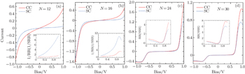
To clarify the length effect on the rectification, we start our calculations from several specific cases by taking N = 12, 16, 24, and 30, respectively. The CC and SC through each device are calculated and displayed in Fig.
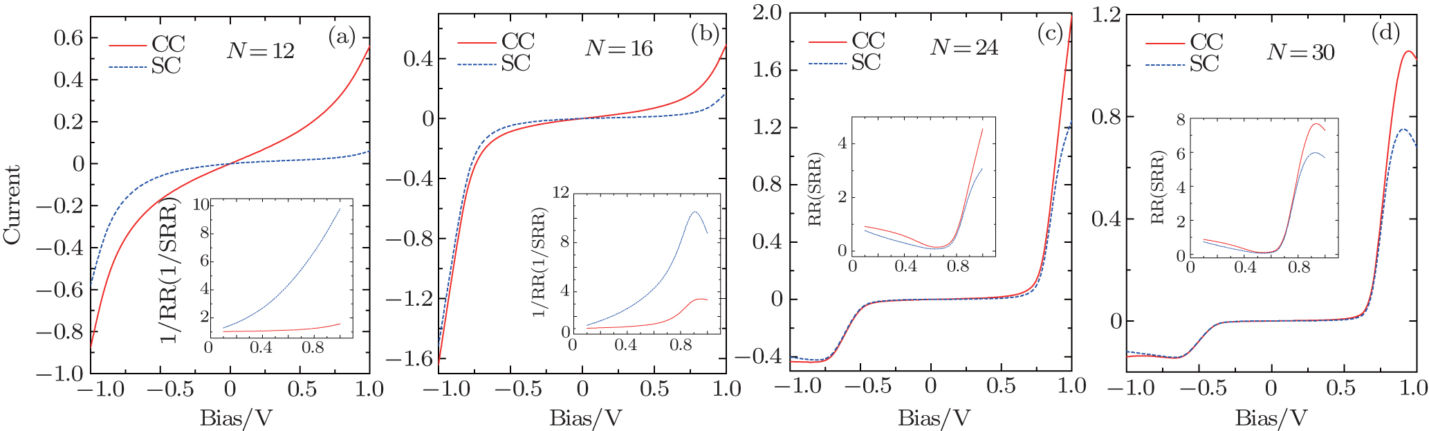 | Fig. 2. Calculated charge current and spin current as a function of bias voltage with (a) N = 12, (b) N = 16, (c) N = 24, (d) N = 30. Solid (red) lines correspond to charge current in units of μA, and dashed (blue) lines indicate spin current in units of ℏ/2e. The inserts are bias-dependent rectification ratios. |
To get a clear view of the dependence of the rectification ratio on the molecular length, we calculate the rectification ratio at |V| = 1.0 V as a function of the molecular length. The result is shown in Fig.
 | Fig. 3. Dependence of charge-current rectification ratio and spin-current rectification ratio on the molecular length at |V| = 1.0 V. The insert is the inverse ratio at short length. |
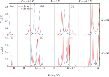
Next, let us try to understand the mechanism of the length effect on the rectification. Firstly, the length-induced inversion of the rectification can be explored by comparing the spin-dependent transmission of N = 16 and N = 30. Figure
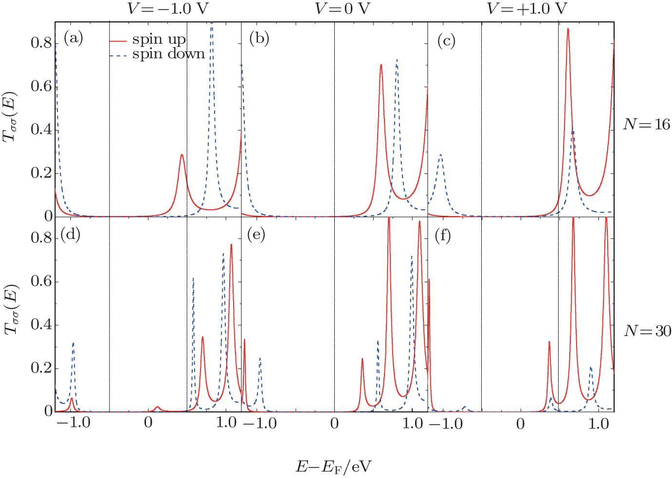 | Fig. 4. Spin-dependent transmission near the Fermi energy at V = 0, ±1.0 V for the different lengths N = 16 (a)–(c) and N = 30 (d)–(f). The vertical dash-dot lines indicate the chemical potentials of electrodes, and the window between them is the conducting bias window. |
The mechanism of the length-induced inversion of rectification in magnetic co-oligomer diodes can be deeply understood in reference to that of D/A type co-oligomer charge-current diodes.[17] In D/A type co-oligomer diodes, there exist two kinds of mechanisms for the rectification: bias-induced asymmetric shift of molecular eigenlevels and bias-induced asymmetric spatial localization of wave functions of the conducting orbitals. The two kinds of mechanisms are very common in molecular rectifiers or even in graphene nanoribbon rectifiers, where the asymmetric evolution of the electronic states may originate from the asymmetric built-in structure of the central molecules or from the asymmetric interfacial contacts with the electrodes.[25,26] In D/A type diodes, the two mechanisms lead to different rectifying directions, and the dominant mechanism of rectification may exchange with molecular length. The magnetic co-oligomer is not a D/A type diode since there is not obvious structural asymmetry of charge density. However, due to the spin splitting of eigenlevels in the left magnetic moiety, the magnetic co-oligmer can be seen as a combination of an A/D type diode for spin-up channels and a D/A type diode for spin-down channels. In the present case, the spin-up channel dominates the transport. Hence, a similar length-induced inversion of rectification is observed for the spin diode. This can be verified by checking the evolution of the spin-dependent eigenstates under bias, which is shown in Fig.
(a) Bias-dependent eigenvalues near the Fermi energy. (b) Evolution of the electronic localization of the spin-up LUMO and spin-down LUMO under biases. Here the molecular length is N = 12.

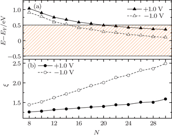
Now we are in the position to clarify the reason of the different length dependence of the rectification ratio in each rectifying direction. Before that, one should make it clear about the length-induced change of molecular eigenstates. In Fig.
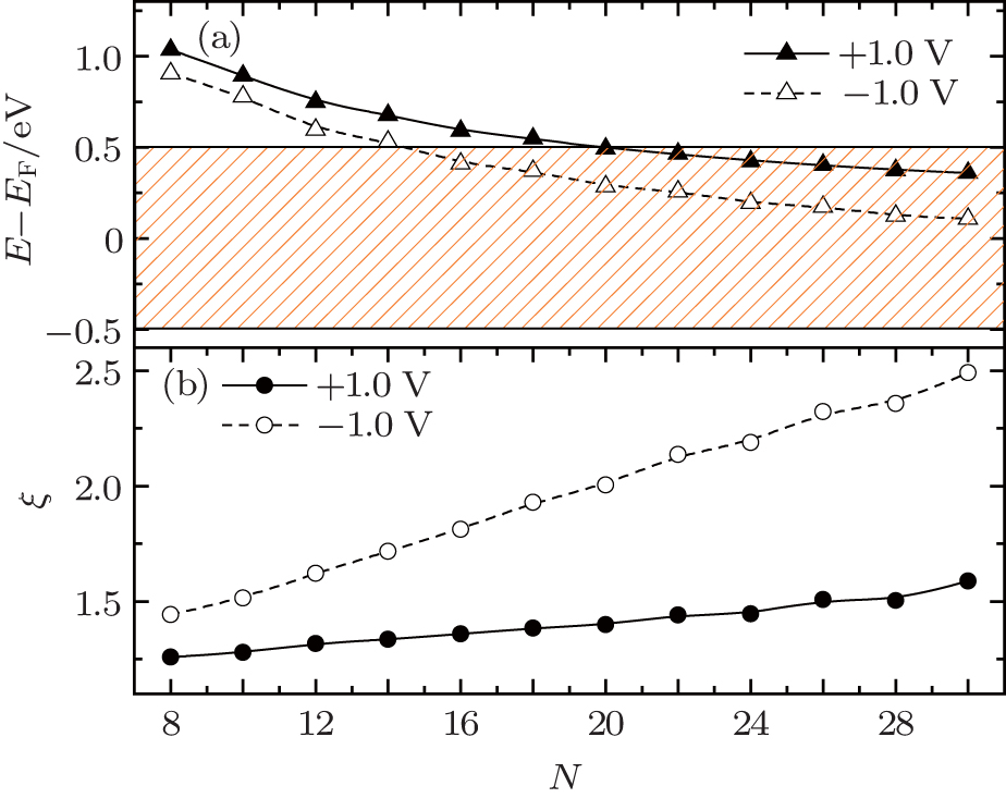 | Fig. 6. Length dependence of (a) the eigenvalue and (b) the electronic localization of the spin-up LUMO. The results at both +1.0 V and −1.0 V are given. The rectangle in panel (a) indicates the bias window. |
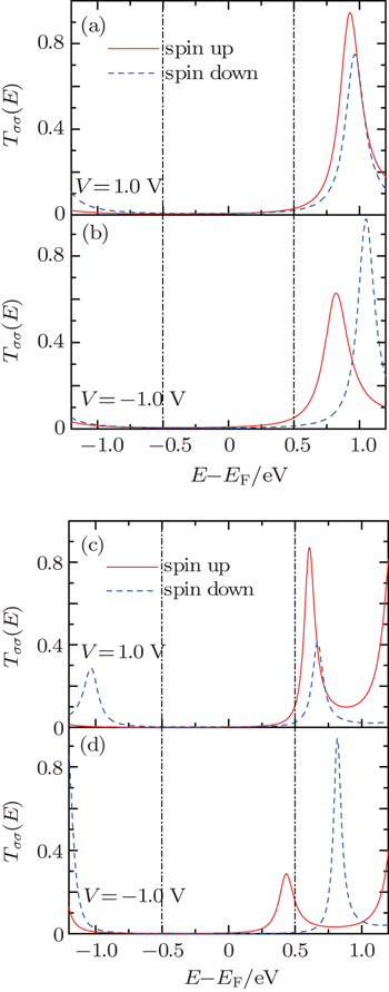
In the short-length region (N < 20), we notice from Fig.
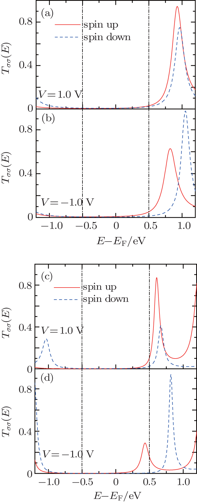 | Fig. 7. Spin-dependent transmission near the Fermi energy at V = ± 1.0 V with (a), (b) N = 10 and (c), (d) N = 16. The window between the vertical dash-dot lines is the conducting bias window. |
In summary, we have investigated the length effect on organic co-oligomer spin rectifiers. The results show that both the rectifying direction and the rectification ratio may be strongly affected by the molecular length. There exists a critical length where the rectifying direction is reversed. In each rectifying direction, the length dependence of the rectification ratio is quite different. For short co-oligomers below the critical length, the inverse RR increases little, while the inverse SRR drops sharply with the length. For long co-oligomers, both the RR and SRR are increased quickly with the length. By analyzing the spin-dependent transmission and the asymmetric evolution of molecular eigenstates, we demonstrate that the origin for the different length dependence of the rectification ratio comes from two different rectification mechanisms, that is, asymmetric shift of molecular eigenlevels and asymmetric spatial electronics localization of the conducting orbitals upon the reversal of bias. This work indicates a possible way to control the rectification in organic spin diodes by molecular length and deserves to be tested by future experiments.
| 1 | |
| 2 | |
| 3 | |
| 4 | |
| 5 | |
| 6 | |
| 7 | |
| 8 | |
| 9 | |
| 10 | |
| 11 | |
| 12 | |
| 13 | |
| 14 | |
| 15 | |
| 16 | |
| 17 | |
| 18 | |
| 19 | |
| 20 | |
| 21 | |
| 22 | |
| 23 | |
| 24 | |
| 25 | |
| 26 | |
| 27 |