

Electronic and magnetic properties at rough alloyed interfaces of Fe/Co on Au substrates: An augmented space study
[Parida Priyadarshini, Ganguli Biplab†,  ]
]
]
|
|


† Corresponding author. E-mail:
Project supported by the INSPIRE Program Division, Department of Science and Technology, India.
We studied the interface electronic and magnetic properties of Fe/Co deposited on Au substrate and researched the effects of roughness at the interfaces within augmented space formalism (ASF). The full calculation is carried out by recursion and tight-binding linear muffin tin orbital (TB-LMTO) methods. The amount of roughness is different at different atomic layers. The formalism is also applied to sharp interface, when interdiffusion of atoms is negligible. Our results of one monolayer transition metal agree with other reported results. A realistic rough interface is also modeled with three and four monolayers of transition metals, deposited on Au substrates.
The interface properties of transition metals and metals significantly contribute to technological applications such as magnetic recording devices and sensors.[1–4] Therefore, the study of layerwise properties at the interface is important.
When a transition metal is deposited on a metal substrate, there is interdiffusion of atoms at the interface due to the difference between their surface energies.[5] When Fe is deposited on Au substrate, Fe atoms are found to segregate[5] and the intermixing of Fe and Au atoms is observed experimentally.[5,6] This intermixing of atoms at the interface leads to rough interface, which is also observed experimentally in this system.[7] Sharp interfaces of Fe/Au with only one Fe monolayer have been considered in various theoretical studies.[8–10] While, in this paper, we studied both sharp and rough layerwise interface properties to research the effect of roughness. The main objective of this paper is to study rough interface properties with three and four ML transition metal depositions on semi-infinite Au substrate. Augmented space formalism (ASF) had also been applied earlier[11] to study the Fe/Au interface with one ML of Fe. Therefore, we have also considered one monolayer (ML) with both sharp and rough interfaces to compare our result with the results in earlier literature.[8–11] Three ML case or more monolayer cases are realistic from the experimental point of view. In our recent work[12] on three MLs of Fe on Ag substrate with rough interface, the result obtained on magnetic properties agrees well with the experimental observations. Therefore we have modeled a realistic rough interface with three and four ML depositions. In this four ML case, the interface is defined as four alloyed layers, two from the transition metal side, and two from the Au side. The interdiffusion of atoms is considered into these four interface layers.
Augmented space formalism[13–16] is a suitable technique to deal with binary disordered alloys, and this formalism has been applied successfully to rough surface and alloyed interfaces.[12,17–19] To deal with the first principle calculation, ASF is combined with the TB-LMTO method. The Hamiltonian in TB-LMTO basis[20] is


The augmented Hamiltonian[16] is


When the recursion method[23] is applied to the augmented Hamiltonian, the averaged Green function can be written in the form of a continued fraction. Infinite continued fraction is to be terminated after a finite terms using a suitable terminator


ASF has been successfully extended to study the properties of almost smooth surfaces and sharp interfaces in the limiting case when roughness is negligible,[12,17–19] by using Viswanath and Müller[25,26] terminator. In our calculations, we used eight-shell augmented space calculation and nine steps of recursion.
Fe is deposited on Au in its bcc phases and there is a large lattice mismatch (42%) between bcc Fe and fcc Au. When Fe is deposited on Au, the layers of bcc Fe are rotated by 45˚ with respect to the Au (001) plane,[5,27–30] which reduces the lattice mismatch to only 0.6%. However, Co is deposited on Au in its fcc phase and there is also 15% lattice mismatch between Co and Au. Therefore, the lattice parameter of the Co overlayer relaxes and it is obtained by energy minimum principle. The relaxed parameters are within 2% lattice mismatch. In our calculations, we considered these relaxed parameters.
Figure
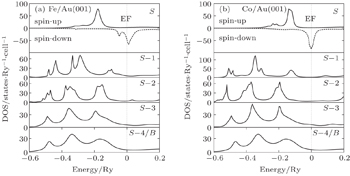
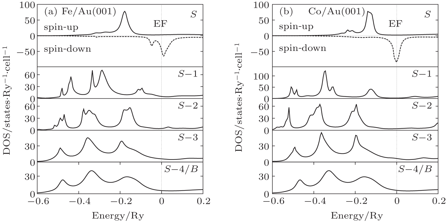 | Fig. 1. Layerwise variation of DOSs for one ML of transition metal (Fe and Co) on Au metal substrates from top most (S) layer to inner atomic layers. Fermi level is reset at zero. (a) Fe/Au(001), (b) Co/Au(001). |
Table
| Table 1. Layerwise magnetic moments (μ) per atom for one layer of transition metals deposited on Au substrate. Here, S represents the top most layer of the interface. x = 0.0 (sharp interface). Comparison is done with the FPLAPW method. . |
The roughness in this one ML case is considered with 5% and 10% interdiffusion of atoms. Figure
 | Fig. 2. Layerwise spin-polarized DOS for one layer of Fe/Co deposited on Au substrate. Here, S and S − 1 represent interface layers. (a) and (d) x = 0 (sharp interface), (b) and (e) x = 0.05, and (c) and (f) x = 0.10 (rough interface). Solid line: spin-up DOS. Dotted line: spin-down DOS. Fermi level is reset at zero. |
Tables
| Table 2. Layerwise magnetic moments (μ) per atom for one layer (S) of transition metals on Au metal substrate. Here, S and S − 1 are T1−xMx and M1−xTx respectively with T and M standing for transition metal and metal atoms respectively, M = Au and x = 0.05 (rough interface). Comparison is done with ASF without surface relaxation. . |
| Table 3. Layerwise magnetic moments (μ) per atom for one layer (S) of transition metals on Au metal substrate. Here, S and S − 1 are T1−xMx and M1−xTx respectively with T and M standing for transition metal and metal atoms respectively, M = Au and x = 0.10 (rough interface). Comparison is done with ASF without surface relaxation. . |
In our earlier work,[12] the obtained rough interface magnetic properties with 5% interdiffusion of atoms for three MLs of Fe on Ag substrates agree with the results in the experimental work.[31,32] Therefore, the study of three ML depositions on Au substrates is also important. There are no experimental and theoretical studies reported for Fe and Co on Au substrate in this for comparison. Table
| Table 4. Layerwise magnetic moments (μ) per atom for three MLs of Fe/Co on Au. S stands for the top most layer, S − 2 and S − 3 are sharp interface layers (x = 0.0). . |
Table
| Table 5. Calculated average and interface magnetic moments (μ) per atom for three layers of transition metals on Au substrates. . |
Next, we modeled a more realistic case where we considered four ML depositions of transition metals on Au substrates. The rough interface is considered as four alloyed layers, two from transition metal layers and the other two from metal substrate layers. In these four layers, the transition metal atoms and metal atoms interdiffuse into each other. Therefore, the interface is defined by four layers I + 2, I + 1, I − 1, and I − 2. The host atom at layers I + 2 and I + 1 is transition metal atom, whereas the host at layers I − 1 and I − 2 is substrate metal atoms. The composition of the alloyed interface at different layers from top to bottom are T95M5, T90M10, M90T10, and M95T5, respectively. Here, T and M stand for the transition metal atom (Fe/Co) and metal substrate atom (Au), respectively.
Figures
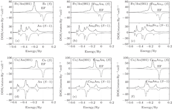
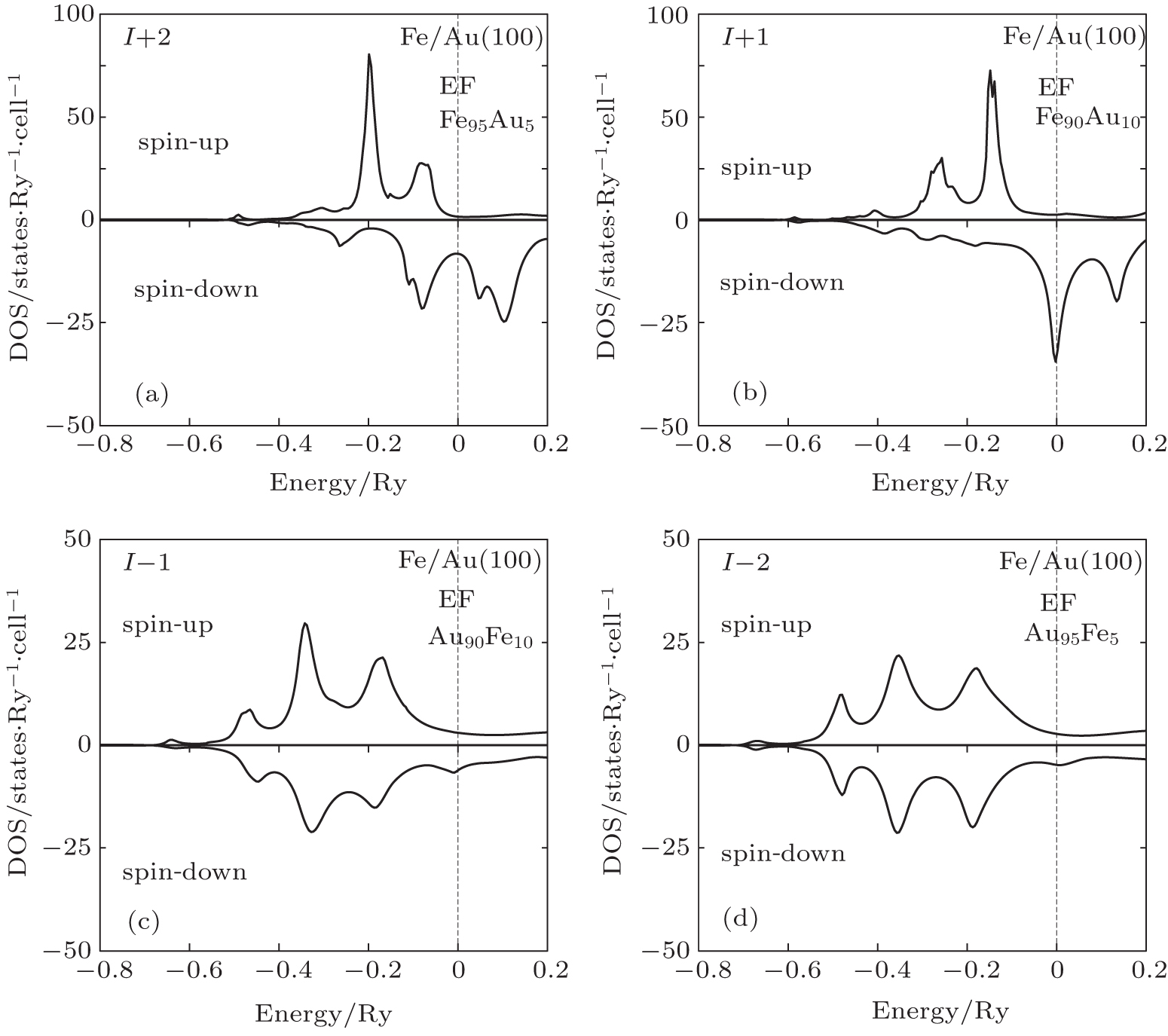 | Fig. 3. Layerwise variation of spin DOS at Fe/Au(001) with rough alloyed interface. Fermi energy is reset at zero. (a) Fe95Au5, (b) Fe90Au10, (c) Au90Fe10, and (d) Au95Fe5. |
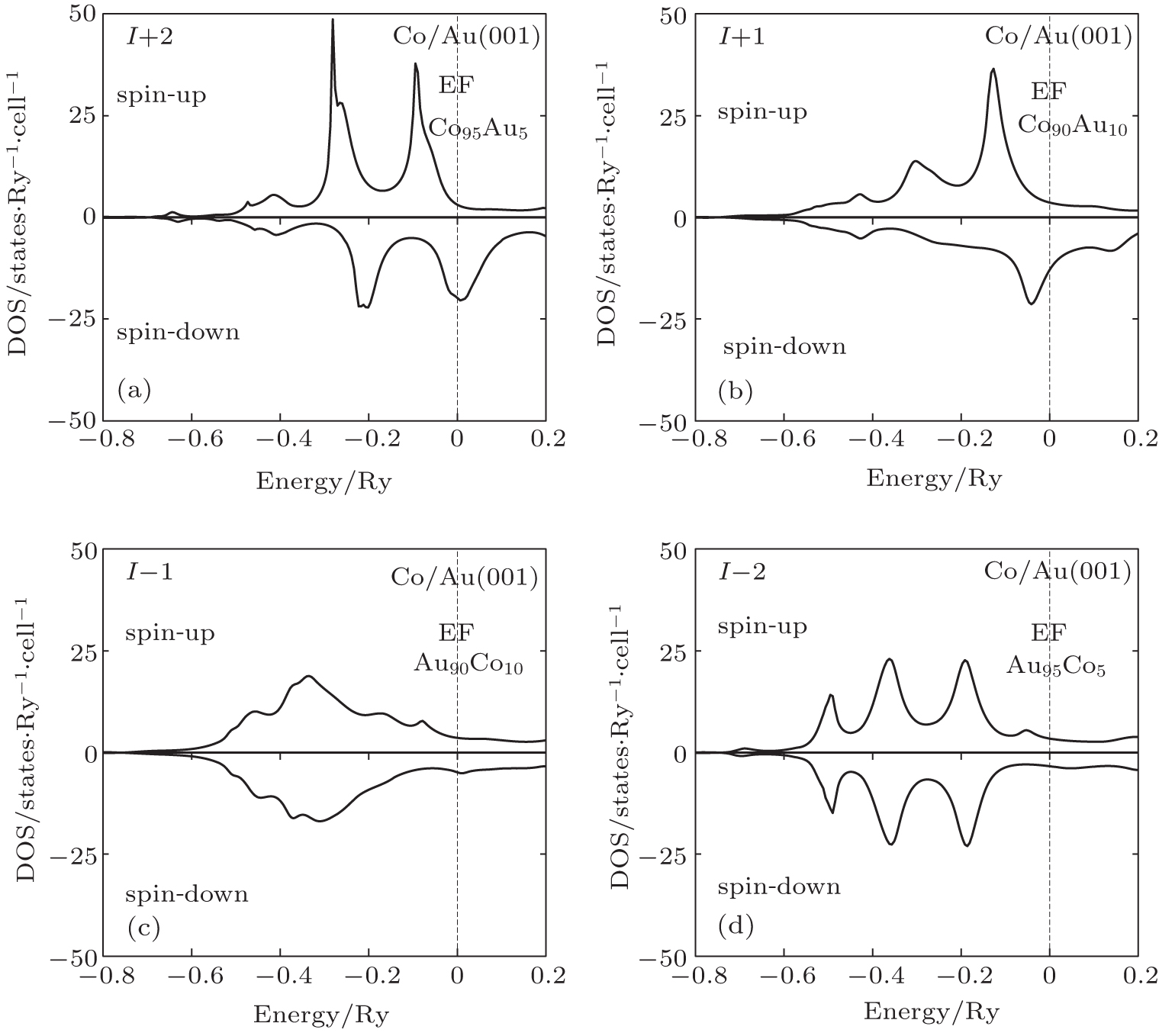 | Fig. 4. Layerwise variation of spin DOS at Co/Au(001) with rough alloyed interface. Fermi energy is reset at zero. (a) Co95Au5, (b) Co90Au10, (c) Au90Co10, and (d) Au95Co5. |
In the case of Fe/Au, the spin-up electronic states at the lower energy region become significant in the I + 2 layer (Fig.
The spin-up and spin-down electronic states are more at the Co top layer in the case of the Co/Au system (Fig.
The effect of roughness is shown in Table 6. The transition metal layers with 5% Au have more magnetic moments compared to that with 10% Au. However, at Au rich layers, the magnetic moment of the I − 1 layer is more compared to that of the I − 2 layer. That is because there are more transition metal atoms in the I − 1 layer, the induced magnetic moments due to Fe/Co are more. The magnetic moment of the Co atom as well as the average magnetic moment of the I + 1 layer is less than its bulk value. This is due to the increase in hybridization between Co and Au atoms. The layerwise magnetic moments at transition metal layers (I + 4 to I + 1) show oscillatory behavior but that in Au substrate layers (I − 1 to I − 5) gradually ceases to zero. The magnetic moment is zero at the fifth substrate (I − 5) layer. Therefore, Au attains bulk properties at the fifth substrate layer for both the systems.
| Table 6. Layerwise magnetic moment (μ) per atom at the four-layer rough interface of two layers of transition metal plus two layers Au substrates. I: boundary of transition metal and Au substrate. Interdiffusion, x = 0.1 at I ± 1 layer and x = 0.05 at I ± 2 layers, and x = 0 at other layers. . |
In this paper, augmented space formalism coupled with the recursion method and the TB-LMTO method has been applied to carry out the layer-based density of states and magnetic moments of rough and sharp interfaces of Fe/Co on Au(001) metal substrates. The calculated DOS and magnetic moment for a sharp interface with one ML deposition agrees well with the results by other first principle calculations. The effects of roughness on DOS and magnetic moments are discussed for one, three, and four ML deposition cases. The obtained rough interface properties with one ML Fe/Co agree with other reported results. The average and interface transition metal magnetic moments get reduced with the increase in roughness in three ML cases. The layerwise magnetic moments cease to zero at the fourth substrate layer in the case of one and three ML depositions, whereas, they reduce to zero at the fifth substrate layer in the case of the four layered interface with four ML depositions.
| 1 | |
| 2 | |
| 3 | |
| 4 | |
| 5 | |
| 6 | |
| 7 | |
| 8 | |
| 9 | |
| 10 | |
| 11 | |
| 12 | |
| 13 | |
| 14 | |
| 15 | |
| 16 | |
| 17 | |
| 18 | |
| 19 | |
| 20 | |
| 21 | |
| 22 | |
| 23 | |
| 24 | |
| 25 | |
| 26 | |
| 27 | |
| 28 | |
| 29 | |
| 30 | |
| 31 | |
| 32 |