Control of microwave signals using bichromatic electromechanically induced transparency in multimode circuit electromechanical systems
School of Physics and Electronic Electrical Engineering, Huaiyin Normal University, Huai’an 223300, China
† Corresponding author. E-mail: chengjiang8402@163.com
Project supported by the National Natural Science Foundation of China (Grant Nos. 11304110 and 11174101), the Jiangsu Natural Science Foundation, China (Grant Nos. BK20130413 and BK2011411), and the Natural Science Foundation of Jiangsu Higher Education Institutions of China (Grant Nos. 13KJB140002 and 15KJB460004).
1. IntroductionThe field of cavity optomechanics and electromechanics,[1–4] which explores the radiation pressure interaction between mechanical and electromagnetic degrees of freedom, has witnessed remarkable progress in the past decade. Cavity opto- and electromechanical systems allow us to cool the mechanical oscillators to their quantum ground state,[5–7] observe the quantum zero-point motion,[8,9] and create squeezed light.[10,11] Moreover, the electromagnetic response of these systems is modified due to mechanical interactions, leading to the phenomena of normal-mode splitting,[12] opto-/electromechanically induced transparency (OMIT/EMIT),[13–20] inverse OMIT,[21,22] electromechanically induced absorption (EMIA),[23] and microwave amplification.[24] OMIT is the analog of electromagnetically induced transparency (EIT),[25,26] where an opaque medium can become transparent to the weak probe field when applying a strong pump beam. EIT has been first observed in atomic vapors and recently in various solid state systems such as quantum wells, dots, and nitrogen-vacancy centers.[27–29] It has been shown to be important in a variety of applications such as slow light,[30] light storage,[31] and enhancement of the nonlinear process,[32] and so on. Likewise, OMIT, accompanied by steep phase dispersion, has also been used to control the group delay of the probe field in optomechanical systems both in optical[15,33] and microwave domains.[34,35] Furthermore, OMIT may find potential applications in the precision measurements of net charge number[36] and environmental temperature.[37]
Recently, multimode optomechanical systems comprising more than two active degrees of freedom have gained increased attention.[38–44] One important class of multimode optomechanical systems consist of devices where a single electromagnetic mode couples to multiple mechanical modes. In the three-mode optomechanical systems where two distinct nanomechanical resonators are coupled to a single electromagnetic cavity, phenomena of hybridization[40,45] and synchronization[46,47] of mechanical modes, and two-mode squeezed states[48] have been investigated. Huang studied the effect of a strong coupling field on the absorptive property of a ring cavity with two mirrors oscillating at slightly different frequencies to a weak probe field and observed double EIT in the output probe field.[49] Moreover, Wang et al. have recently studied the optomechanical analog of two-color EIT in a hybrid optomechanical system consisting of a cavity and a mechanical resonator with a two-level system (qubit).[50] Two-color EIT has already been widely discussed in a variety of atomic systems.[51,52]
In this paper, we first investigate the microwave response of the three-mode circuit electromechanical system to a weak probe field in the presence of a strong pump field. We find that there are two transparency windows in the probe transmission spectrum, which can be named as bichromatic electromechanically induced transparency (EMIT). Using the experimental parameters, we then numerically calculate the group delay of the microwave probe field as a function of the pump power. Our results show that the maximum group delay of the transmitted probe field is about 0.12 ms and the signal advancement of the reflected probe field is close to 0.27 ms, which can be further increased by reducing the damping rate of the mechanical resonator. This hybrid system with bichromatic EMIT provides a good medium for controlling microwave photons at different frequencies and may find applications in quantum information processing. It should be pointed out that the physical origin for the double EMIT is almost the same as the one in Ref. [49], but the electromechanical system under consideration works in the microwave regime while the ring cavity with nanomechanical mirrors operates in the optical regime. Compared to the ring cavity, it is much easier to integrate more mechanical resonators with a single microwave cavity to compose a multimode electromechanical system where multiple EMIT can be observed, which could be useful for multi-channel quantum information processing.
2. Model and methodWe first consider a general multimode circuit electromechanical system, where N mechanical resonators are individually coupled to a common microwave cavity. The motion of each mechanical resonator, expressed as time-varying capacitors Ck, independently modulates the total capacitance C, and hence, the cavity frequency ωc. The single-photon coupling strength gk = Gkxzp,k is the product of Gk = (ωc/2C)∂Ck/∂xk, denoting the cavity resonance frequency change on each mechanical displacement, and the mechanical resonator’s zero-point fluctuation  (mk and ωk are the effective mass and resonance frequency of each resonator, respectively). The microwave cavity is driven by a strong pump field Epu with frequency ωpu and a weak probe field Epr with frequency ωpr simultaneously. In a rotating frame at the pump frequency ωpu, the general Hamiltonian of the multimode electromechanical system reads as follows:[40]
The first term describes the energy of the microwave cavity mode, where
a† (
a) is the creation (annihilation) operator of the cavity mode and
Δpu =
ωc −
ωpu is the cavity-pump field detuning. The second term gives the energy of the
N mechanical modes with creation (annihilation) operator

The third term denotes the interaction between the cavity field and the
N mechanical resonators. The last two terms represent the interaction between the cavity field and the two input fields, where
Epu and
Epr are related to the power of the applied microwave fields by
and

respectively,
Ω =
ωpr −
ωpu is the detuning between the probe field and the pump field. The microwave cavity has a linewidth of
κ =
κi +
κe, where
κi is the intrinsic decay rate and
κe =
ηcκ is due to external coupling to the feedline.
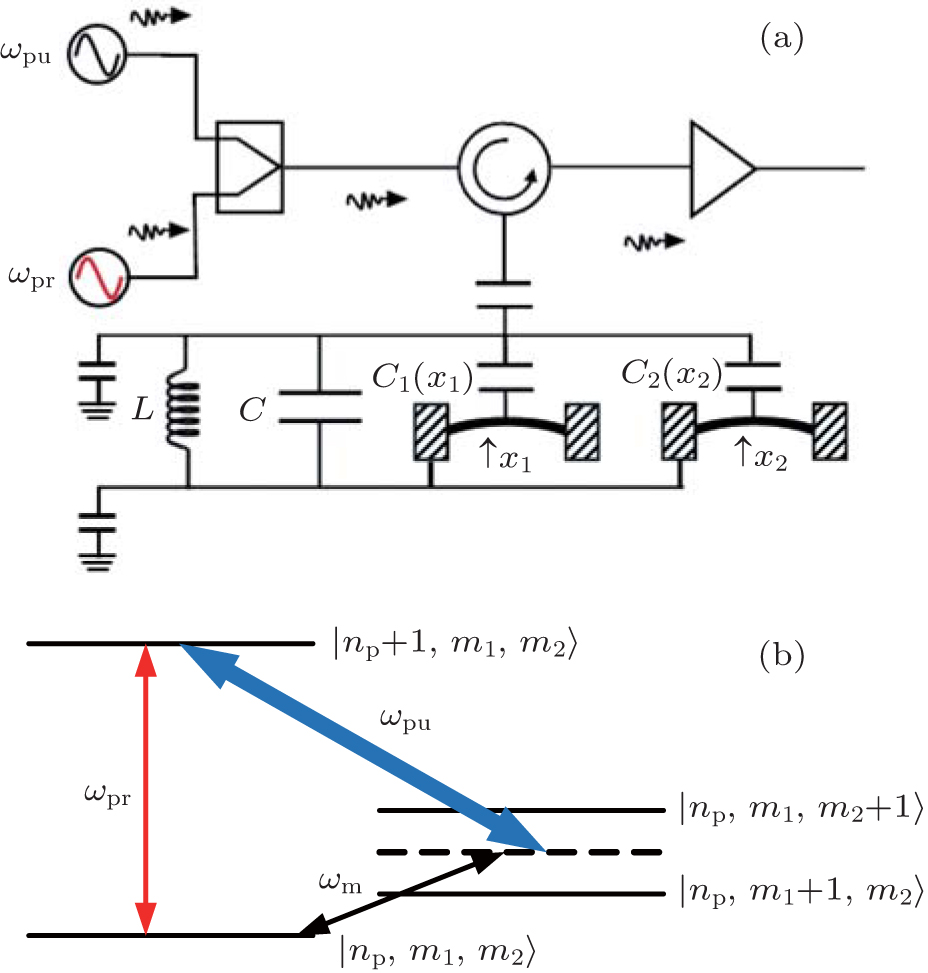
The dynamics of the system can be described by a set of nonlinear Langevin equations. For simplicity, we will focus on two mechanical resonators, i.e., N = 2, which is the situation that has been intensively investigated,[40,45–48] see Fig. 1 for the schematic diagram. Starting from the Hamiltonian and applying the Heisenberg equations of motion for operators a and Qk (k = 1,2) (which is defined as the dimensionless amplitude of the mechanical oscillations  ), we derive the following quantum Langevin equations:


where the decay rates for the microwave cavity (
κ) and the two mechanical oscillators (
γ1,
γ2) have been introduced classically, and
ain and
ξ1 (
ξ2) are the zero-mean quantum and thermal noise terms. Under the assumption that the pump field is much stronger than the probe field (
Epu ≫
Epr), we derive the steady-state solutions to Eqs. (
2)–(
4) by setting all the time derivatives to zero. They are given by

where Δ =
Δpu –
g1Qs,1 –
g2Qs,2 is the effective cavity detuning including radiation pressure effects. Without loss of generality, we have assumed the steady-state value
as to be real and positive. Subsequently, we follow the typical procedure and solve Eqs. (
2)–(
4) perturbatively by rewriting each Heisenberg operator as the sum of its steady-state mean value and a small fluctuation,

Inserting these equations into the Langevin equations Eqs. (
2)–(
4) and assuming |
as| ≫ 1, one can safely ignore the second-order small terms such as δ
a†δ
a, δ
aδ
Q1, and δ
aδ
Q2 which can result in higher-order sideband generation.
[53] In addition, since the drives are weak, but classical coherent fields, we will identify all operators with their expectation values, and drop the quantum and thermal noise terms.
[14] Then the linearized quantum Langevin equations can be obtained as follows:

In order to solve the linearized equations (
7)–(
9), we use the ansatz
[54] δ
a(
t) =
a+e
−iΩt +
a−e
iΩt, δ
Q1(
t) =
Q+,1e
−iΩt +
Q−,1e
iΩt, and δ
Q2(
t) =
Q+,2e
–iΩt +
Q−,2e
iΩt. Upon substituting the above ansatz into Eqs. (
7)–(
9), we derive the following solution:
where

and
np = |
as|
2. Here,
np approximately equal to the number of pump photons in the cavity, is determined by the following equation:
The microwave response of the three-mode electromechanical system to the probe field under the influence of the strong pump field can be obtained by calculating the output field transmitted by the cavity. According to the input–output relation[55]  one can obtain the output field

We can see from Eq. (
13) that the output field contains two input components (
ωpu and
ωpr) and one generated four-wave mixing (FWM) component at the frequency 2
ωpu –
ωpr. Here, we are not interested in four-wave mixing process, thus the expression of
a− is not written out. The transmission of the probe field, defined by the ratio of the output and input field amplitudes at the probe frequency, is then given by

The pump field cannot only modify the transmission of the probe field, but also result in a rapid phase dispersion
ϕT = arg(
tp) of the transmitted probe field across the transmission window, which can lead to significant group delay expressed as

3. Numerical results and discussionIn our numerical calculations, we use the parameters of a realistic three-mode circuit electromechanical system:[40] ωc = 2π × 6.986 GHz, κ = 2π × 6.2 MHz, κe = 2π × 4.8 MHz, ω1 = 2π × 32.1 MHz, ω2 = 2π × 32.5 MHz, γ1 = γ2 = γm = 2π × 930 Hz, g1 = 2π × 39 Hz, g2 = 2π × 44 Hz. We can see that ω1 > κ and ω2 > κ, therefore the system operates in the resolved-sideband regime, which is beneficial for the electromechanically induced transparency. In what follows, we investigate the microwave response of this coupled system in the two cases of equal and different mechanical frequencies separately.
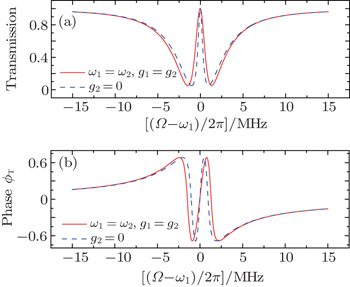
First, we consider the case in which the resonance frequencies of the two mechanical resonators are the same, i.e., ω1 = ω2 = 2π × 32.1 MHz. In addition, their optomechanical coupling strengths are equal, we assume g1 = g2 = 2π × 39 Hz. Figure 2 plots the transmission and phase of the transmitted probe field as a function of the probe detuning (Ω – ω1)/2π when the pump field is tuned to the red sideband of the cavity resonance Δpu = ω1 with Ppu = 4 μW. The red solid curve corresponds to the situation where ω1 = ω2 and the blue dashed curve represents the case in the absence of the second mechanical resonator. In both cases, it can be seen from Fig. 2(a) that a single transparency window appears when the beat frequency Ω is nearly resonant with the frequency of the mechanical resonator, which is due to the destructive interference between the probe field and the generated anti-Stokes field. Such a phenomenon, usually termed as optomechanically induced transparency (OMIT) or electromechanically induced transparency (EMIT), has been well understood in the generic optomechanical systems where a mechanical resonator is coupled to a electromagnetic cavity.[14,56] We can see that even though a common cavity is coupled to two identical mechanical resonators, there is still only a single transparency window, which results from the fact that the interaction between two resonators is too weak to split the single OMIT. Similar phenomenon exists in a ring cavity with two movable nanomechanical mirrors with the same frequencies.[49] However, Ma et al. and Li et al. have recently shown that double OMIT can still occur due to the quantum interference between three pathways when the two identical resonators have direct interaction.[44,57] Furthermore, the concomitant phase dispersion in Fig. 2(b) indicates that this effect can be used to slow and advance electromagnetic fields in mechanical degrees of freedom.[15,35] Note that the width of the transparency window when the two mechanical resonators have equal resonance frequency (ω1 = ω2) is larger than the case in the absence of the second mechanical resonator (g2 = 0). The reason is that the width of the transmission window is given by the modified mechanical damping rate γ1(1 + 2C1) and γ1(1 + C1), respectively, where  denotes the optomechanical cooperativity.[14]
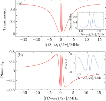
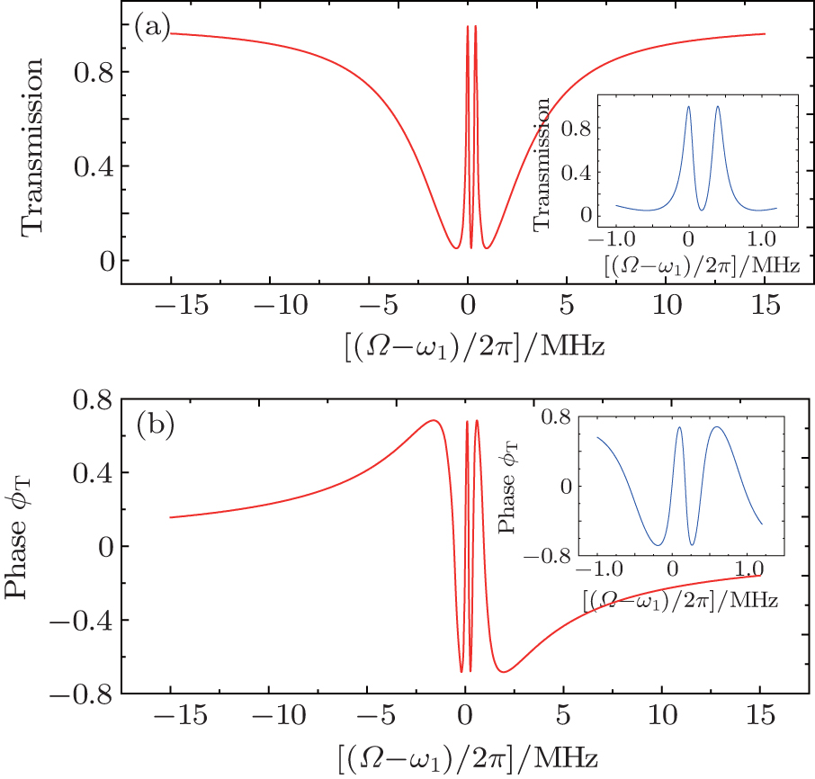
In the following, we mainly consider the case in which the frequencies of the two mechanical resonators are different but their damping rates are equal, which is the real situation in the experiment of Ref. [40]. When the pump field is red detuned by an amount ωm = (ω1 + ω2)/2 with Ppu = 1 μW and the probe field is then scanned through the cavity resonance, in Fig. 3 we plot the magnitude and phase of the probe transmission as a function of the probe detuning (Ω – ω1)/2π. Different from Fig. 2, there are two transmission peaks in the probe transmission spectrum, which displays that the input probe field could be simultaneously transparent at two symmetric frequencies. The inset of Fig. 3(a) is the zoom-in view of the two peaks, from which we can judge that the two peaks locate at Ω = ω1 and Ω = ω2, respectively. An intuitive physical picture explaining the bichromatic EMIT can be given in the energy level diagram shown in Fig. 1(b), where np represents the number of the intracavity photon, and m1 and m2 denote the phonon numbers in the two mechanical resonators with resonance frequencies ω1 and ω2, respectively. The pump field is red detuned by an amount ωm, i.e., Δpu = ωc – ωpu = ωm, and the probe field of frequency ωpr = ωpu + Ω scans through the cavity resonance. The simultaneous presence of pump and probe fields induces a modulation at the beat frequency Ω of the radiation pressure force acting on the mechanical resonators. When this modulation is close to the mechanical resonance frequency ωk (k = 1,2), the vibrational mode is excited coherently, giving rise to Stokes (ωs = ωpu – ωk) and anti-Stokes scattering (ωas = ωpu+ωk) of light from the strong pump field. If Δpu = ωm, Stokes scattering is strongly suppressed because it is highly off-resonant with the microwave cavity and we can assume that only the anti-Stokes field builds within the cavity. However, when Ω = ωk, the probe field is nearly resonant with the cavity, which is degenerate with the generated anti-Stokes fields. As a consequence, destructive interference between these two fields can suppress the build-up of an intracavity probe field and lead to two transparency windows in the probe transmission spectrum at Ω = ω1 and Ω = ω2. Figure 3(b) shows that the phase of the probe transmission suffers a steep positive dispersion within the two transparency windows, which could be used as a tunable delay for microwave signals. Moreover, the width of the two transparency windows is given by γeff,k = γk(1 + Ck) with 
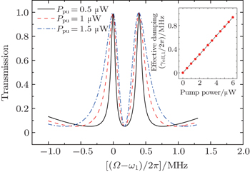
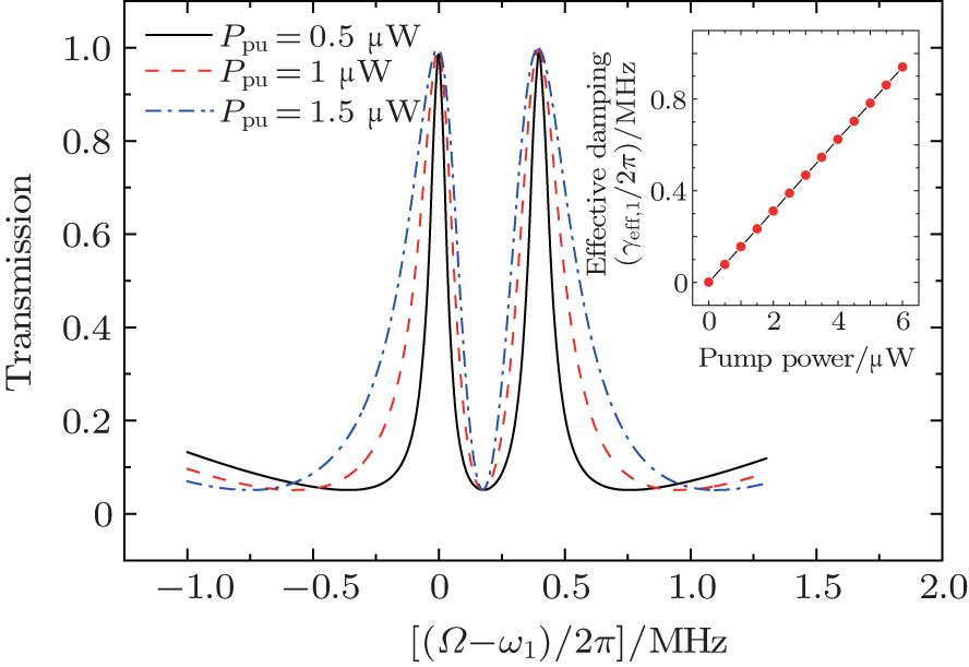
The intracavity photon number np can be greatly increased by enhancing the pump power Ppu according to Eq. (12), which will result in broadening of the transparency windows, as shown in Fig. 4. From this figure, one can see that the transparency window is fully controllable via the applied microwave field, the window expanding and contracting with the power of the pump field. The inset of Fig. 4 shows a linear relationship between the pump power and the width of the window locating at Ω = ω1.
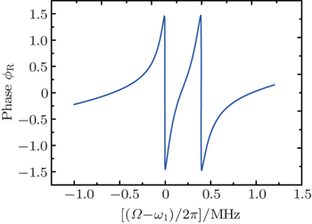
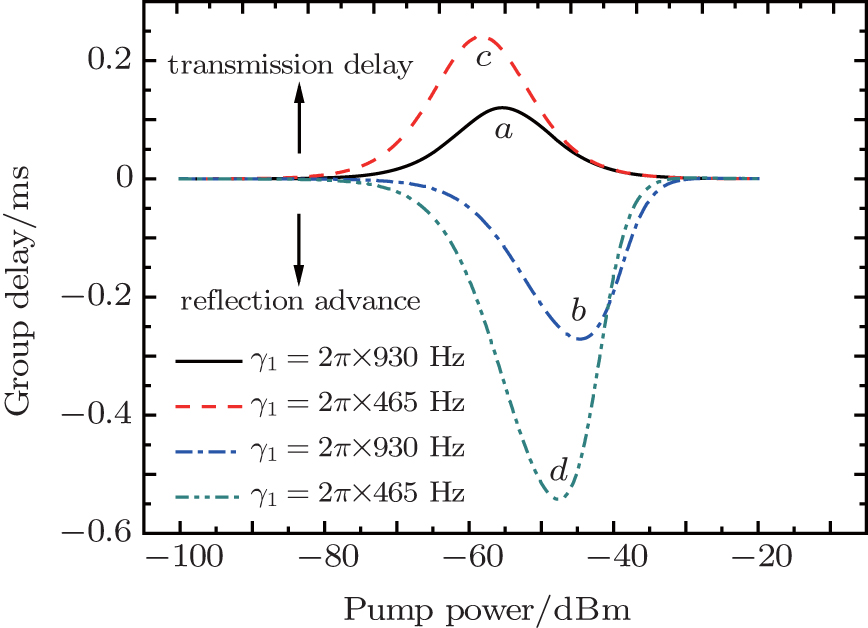
In Fig. 5, we plot the phase dispersion of the reflected probe field as a function of the probe detuning (Ω – ω1)/2π for Ppu = 1 μW. Different from Fig. 3(b), it can be seen that there is steep negative phase shift around Ω = ω1 and Ω = ω2. The derivative of a such a phase shift gives the group advancement due to causality-preserving superluminal effect. Both the two transparency windows and the corresponding phase dispersion shown in Figs. 3 and 5 can be used for controlling the group delay of the microwave signals. For illustration, we consider the narrow transparency window and sharp phase dispersion at Ω = ω1. The group delays of the transmitted and reflected probe fields as a function of the pump power are plotted in Fig. 6 with Δpu = ωm and Ω = ω1. Solid curve a and dashed curve b represent, respectively, the group delays of the transmitted and reflected probe field with the realistic experimental parameter, i.e., γ1 = 2π × 930 Hz. It can be seen that the group delays of the transmitted probe field are positive but those of the reflected probe field are negative when the power of the pump field is varied, which represent the delay and advancement of the microwave signals, respectively. The maximum transmission group delay is  ms and the reflection signal advancement is
  ms. The physical reason for the slow and fast light effects in optomechanical systems is the fast phase shift acquired by the probe field during its propagation through the optomechanical cavity under the influence of the strong pump field.[14–16,35] The positive phase change indicates the normal dispersion with τg > 0, which represents the slow light effect. On the other hand, the negative phase shift corresponds to the anomalous dispersion with τg < 0, which indicates the fast light effect.
Moreover, we consider the effect of the mechanical damping rate on the group delay. In Ref. [35], Zhou et al. has shown analytically that the maximum group delay is inversely proportional to the mechanical damping rate. Here, we assume that γ1 = 2π × 465 Hz, as shown in curves c and d in Fig. 6. One can see that the maximum delays are almost twice the values in curves a and b. Therefore, the group delay of the microwave signal can be further increased by reducing the mechanical damping rates, which can be as low as several Hz.[35,58] Compared to the generic circuit electromechanical systems in which an electromagnetic cavity is coupled to a single mechanical resonator, one advantage of the 3-mode hybrid system we study here is that it allows for more controllability to realize double EMIT, which can also exist when the cavity-pump detuning Δpu = ω1 or Δpu = ω2. The two transparency windows still locate at Ω = ω1 and Ω = ω2. As a result, group delay of the probe field at a wider range of frequencies can be effectively tuned with negligible losses by the frequency and power of the pump field. Finally, it is worth noticing that here we only consider the situation where the pump field drives the cavity mode on the red sideband, i.e., Δpu = ωm. Future work will include the situation in which the pump field is resonant with the blue sideband of the cavity mode, i.e., Δpu = −ωm. In such a case, coherent oscillation of the mechanical resonator is induced when Ω = – ωk (k = 1,2). The anti-Stokes field at the frequency ωpu + ωk is strongly suppressed because it is off-resonant with the cavity field, whereas the Stokes field at the frequency ωpu – ωk ≈ ωc is enhanced. Constructive interference between the Stokes field and the degenerate probe field can lead to double electromechanically induced absorption[23] and parametric amplification[24] in probe transmission within two very narrow frequency windows.
4. ConclusionTo summarize, we have studied the tunable delay and advancement of microwave signals based on double EMIT in a 3-mode circuit electromechanical system. When the frequencies of the two mechanical oscillators are different, two transparency windows appear in the probe transmission spectrum due to destructive interference between the probe field and the anti-Stokes field caused by the two distinct mechanical vibrations. The narrow transparency window and the corresponding steep phase dispersion allow for controlling the group delay of the microwave probe field with negligible losses, which can be tuned by the power of the pump field. Our theoretical results show that the maximum group delay of the transmitted probe field is ∼0.12 ms, and the signal advance of the reflected probe field is about 0.27 ms for the experimental parameters in Ref. [40]. The results of this paper are also applicable to other three-mode cavity optomechanical systems where two mechanical oscillators are coupled to a single optical cavity.


 , Cui Yuanshun, Bian Xintian, Li Xiaowei, Chen Guibin]