


Analysis and experiments of self-injection magnetron
[Zhang Yi, Ye Wen-Jun, Yuan Ping, Zhu Huan-Cheng, Yang Yang†,  , Huang Ka-Ma]
, Huang Ka-Ma]
|
|


† Corresponding author. E-mail:
Project supported by the National Basic Research Program of China (Grant No. 2013CB328902) and the National Natural Science Foundation of China (Grant No. 61501311).
Magnetrons are widely used in microwave-based industrial applications, which are rapidly developing. However, the coupling between their output frequency and power as well as their wideband spectra restricts their further application. In this work, the output frequency and power of a magnetron are decoupled by self-injection. Moreover, the spectral bandwidth is narrowed, and the phase noise is reduced for most loop phase values. In order to predict the frequency variation with loop phase and injection ratio, a theoretical model based on a circuit equivalent to the magnetron is developed. Furthermore, the developed model also shows that the self-injection magnetron is stabler than the free-running magnetron and that the magnetron’s phase noise can be reduced significantly for most loop phase values. Experimental results confirm the conclusions obtained using the proposed model.
Nowadays, many microwave-based industrial applications are rapidly developing, such as plasma and microwave chemical vapor deposition, which require high intensive electromagnetic fields.[1,2] Meanwhile, microwave wireless power transmission systems and space solar power satellite/station systems need high continuous microwave power.[3–7] The energies of single microwave sources can hardly meet these demands. An attractive method of generating high continuous microwave power is coherent, magnetron-based power-combination since magnetrons are low-cost and highly efficient.[3–5] However, the coupling between a magnetron’s output frequency and power presents one of the significant obstacles to coherent power-combination, because both the frequency and power vary with the anode current of the magnetron. Hence, it is difficult to adjust each magnetron to exactly the same frequency and power to achieve a high combined efficiency.[8–10] On the other hand, free-running magnetrons produce wideband spectra with high noise, restricting the applications of magnetrons in communications and other scientific fields.[11]
The conventional methods of addressing the coupling between the output frequency and power as well as reducing the noise of the free-running magnetron spectra include external-injection locking, power supply system improvement, and the combination of these two techniques.[6,11–16] Usually, external-injection locking can lock the output frequency of a magnetron at the injection frequency, thus improving the phase noise. However, the locking bandwidth depends greatly on the injection ratio. Therefore, expensive solid-state drivers are required to achieve wide locking bandwidths for high-power magnetrons.[12–15] Furthermore, the power supply system also significantly affects the output performance of a magnetron. Therefore, previous researchers also studied the combination of external-injection locking and using an improved power supply system to reduce the injection ratio and to improve the noise performance.[6,11] However, all these systems contain microwave active circuits, and thus are costly and fragile.
In this study, we develop a novel way of controlling a magnetron’s output frequency and power individually by introducing a feedback loop, which contains no microwave active device. Moreover, the output spectrum of the self-injection magnetron is narrowed, and the phase noise is reduced for most loop phase values. In order to predict the frequency variation with loop phase and injection ratio, a theoretical model based on a circuit equivalent to a magnetron is developed. Numerical analysis indicates that the frequency variation with loop phase can be approximated by a sine curve with a stretched declining region and a compressed rising region. Furthermore, the self-injection magnetron is found to be more stable than the free-running magnetron except that the loop phase is around (2k + 1)π. The phase noise is also reduced when the magnetron is stabler. Experimental results demonstrate that the frequency of the self-injection magnetron changes with loop phase, while the output power remains steady under a stable anode current. The spectral bandwidth of the self-injection magnetron is also narrowed for most loop phase values except for π and 5π/4. The phase noise in the narrowed spectra is also reduced compared with that of a free-running magnetron spectra. The experimental results well match the theoretical predictions.
The rest of this paper is organized as follows. In Section 2, the relation between frequency and noise performance of the self-injection magnetron is obtained based on the equivalent circuit model. Numerical analyses are also performed to investigate the effects of loop phase and injection ratio on the frequency and noise performance in this section. Experiments are carried out to test the theoretical predictions. The experimental system is depicted in Section 3. The experimental results as well as their comparison with the theoretical predictions are discussed in Section 4. Finally, some conclusions are drawn from the present investigation in Section 5.
The equivalent circuit model for the magnetron which has the pulling and pushing effects is shown in Fig.
 | Fig. 1. Equivalent circuit model of magnetron. |
The oscillation equation of the circuit is shown as


Therefore, the phase differential equation of an injection magnetron can be obtained from Eqs. (


For a self-injection magnetron, the injection signal is just a portion of the output of the magnetron itself. Therefore, the injection frequency ωi is exactly the same as the output frequency ωout of the magnetron. Moreover, θ always remains constant in the steady state. Hence, the steady-state equation of a self-injection magnetron can be expressed as follows:

Equation (
Even though the output power and frequency can be decoupled by self-injection, the detailed relationship between the output frequency and the system parameters should be studied further by using Eq. (

The stability of self-injection oscillators has been analyzed previously.[18] A magnetron is also a type of oscillator, and the circuit equivalent to a magnetron is the same as the analyzed parallel-resonant circuit in Ref. [18]. Therein, it was reported that the stability requirement for a self-injection parallel-resonant oscillator can be expressed as

However, it was also reported that the loop phase was assumed to be constant in the analyses and that the effects of the oscillator frequency shift and loop phase variation should be carefully studied in the future.[16] Therefore, if the frequency shift is considered, the loop phase of a self-injection magnetron in a steady state can also be expressed as θf(ωout/ωf). Then, equation (

Equation (

The phase noise is the ensemble average of the phase fluctuation power spectral density. With small phase fluctuation, the phase noise will be low.[18,19] To further analyze the relationship between the phase noise of a free-running magnetron and a self-injection magnetron, Bn(t) is introduced to represent the time-varying noise susceptance.[19] Then the equation of the self-injection magnetron with noise can be described as

Assuming that the noise is a small perturbation to a noise-free solution, we can write


To convert the time-domain phase fluctuations into a frequency-domain phase noise, we can perform the Fourier transform of Eq. (

The power spectrum of the magnetrons phase fluctuation is calculated from 


In previous studies, to conduct theoretical analyses, the output frequency ωout was approximated as being equal to the free-running frequency ωf of the oscillator, and the loop phase was also approximated as a constant. The previous researchers stated in the conclusions that the frequency shift and loop phase variation should be carefully studied in the future.[19] If equation (
Equation (
 | Fig. 2. Frequency variations with adjustable phase for different loop phases. |
The frequency variation with adjustable loop phase θfa can be approximated by a sine curve with a stretched declining region and a compressed rising region as shown in Fig.
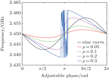
Figure
 | Fig. 3. Frequency variations with phase for different injection ratios. |
The stability of a self-injection magnetron is described by Eq. (
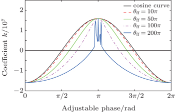
Figure
 | Fig. 4. Variations of k with adjustable phase loop phase for different values of θf (k < 0: noise reduced). |
Figure
 | Fig. 5. Variations of k with adjustable phase for different injection ratios (k < 0: noise reduced). |
Figures
The phase noise of a magnetron is closely related to its stability. With increasing magnetron stability, the fluctuation of the phase difference between the magnetron output and self-injection signal approaches to zero, and the phase noise decreases. Moreover, the relationship between the phase noise of a self-injection magnetron and a free-running magnetron is described in Eq. (
 | Fig. 6. Plots of phase noises versus offset frequency for free-running magnetron and different θfa values of self-injection magnetrons. |
The spectral characteristics of the phase noise in a self-injection magnetron are shown in Fig.
The experimental system of the self-injection magnetron is depicted in Fig.
 | Fig. 7. (a) Experimental setup of self-injection magnetron system, and (b) photograph of experimental self-injection system. |
The output spectrum and power were coupled by a double directive coupler and measured by a Tek RSA6100B spectrum analyzer and an AV2433 power meter, respectively. The RSA6000 Series provides the functionality of a high-performance spectrum analyzer, wideband vector signal analyzer, and the unique trigger-capture-analyze capability of a real-time spectrum analyzer all in a single package. The DPX spectrum of the Tek RSA6100B spectrum analyzer provides an intuitive understanding of time-varying RF signals with color-graded displays based on frequency of occurrence.[22]
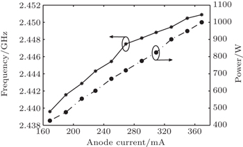
To measure the output frequency and power as well as noise performance of the free-running magnetron, the injection port and the output port of the phase shifter are terminated with matched loads. The variations of output frequency and power with the anode current are shown in Fig.
 | Fig. 8. Variations of frequency and power with anode current in free-running magnetron. |
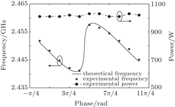
To measure the performances of the self-injection magnetron, a coaxial cable was used to connect the coupled output power to the injection port. The anode current was maintained at 350 mA, while the phase shift was changed from 0 to 5π/2 in steps of π/4. The variations of frequency and power are shown in Fig.
 | Fig. 9. Variations of frequency and power with phase shift, where the power remains steady under stable anode current, while the frequency varies with the loop phase. |
It is clear that frequency and power are decoupled as shown in Fig.
To test the theoretical frequency prediction, the theoretical frequency curve with a fixed loop phase around is shown in Fig.
The spectrogram function of the Tek RSA6100B spectrum analyzer can display the variations of frequency and amplitude with time. A spectrogram of the self-injection magnetron is shown in Fig.
 | Fig. 10. Spectrograms of self-injection magnetron with different phase shifts. |
In Fig.
The experimental results in Fig.
 | Fig. 11. DXP spectra of free-running and self-injection magnetrons: (a) DXP spectra of free-running magnetron, (b) DXP spectra of self-injection magnetron with phase shift of π/4, and (c) DXP spectra of self-injection magnetron with phase shift of π. |
The DXP spectra of the free-running and self-injection magnetrons are compared in Fig.
Figure
 | Fig. 12. Variations of phase noise with offset frequency for free running magnetron and different phase shifts of self-injection magnetrons. |
By introducing a feedback loop into a magnetron system in this study, the output frequency and power can be decoupled. The output power is controlled by the anode current, and the frequency can be adjusted by changing the loop phase. Meanwhile, the output frequency bandwidth is narrowed, and the phase noise of the self-injection magnetron is reduced for most loop phase values. Moreover, a theoretical model based on a circuit equivalent to a magnetron is developed. The frequency variation with changing loop phase can be approximated by a sine curve with a stretched declining region and a compressed rising region. Furthermore, more accurate stability and noise performance analysis are performed for a self-injection magnetron with considering the frequency shift and loop phase variation. The self-injection magnetron is stabler except that the loop phase value is around (2k + 1)π. The phase noise can also be reduced if the magnetron is stabler.
Self-injection magnetron provides the basis for a new coherent power-combining approach because it can adjust each individual magnetron to the same values of output frequency and power without external-injection locking. After the frequency of each magnetron is adjusted to the same value, the phase difference between the sources of the power-combining system can be adjusted by a pulse of biased frequency. This work is still ongoing. On the other hand, since the self-injection technique can narrow the output frequency bandwidth and reduce the magnetron phase noise, it can broaden the areas in which magnetrons can be applied to critical noise required fields such as communications and scientific fields.
| 1 | |
| 2 | |
| 3 | |
| 4 | |
| 5 | |
| 6 | |
| 7 | |
| 8 | |
| 9 | |
| 10 | |
| 11 | |
| 12 | |
| 13 | |
| 14 | |
| 15 | |
| 16 | |
| 17 | |
| 18 | |
| 19 | |
| 20 | |
| 21 | |
| 22 |