1. IntroductionThe magnetization reversal processes of Fe ultrathin films play an important role in magnetic-storage materials and have attracted sustained interest for both fundamental and technological reasons over the past few decades.[1–4] The magnetization reversal processes of Fe films occur via coherent rotation and/or domain wall displacement.[5–7] For Fe (001) single crystalline films, the magnetization reversal processes are primarily dominated by domain wall displacement and can be treated as coherent rotations only at a high external field.[8–10]
Owing to the high sensitivity down to sub-nm thickness, experimental simplicity and local probing nature, the magneto-optic Kerr effect (MOKE) has been widely employed to investigate the magnetization reversal process.[11] The MOKE exploits the alteration of the polarization state of light reflected from a magnetic surface, which is exceedingly applicable to the thin films.[12–14] In the measurements of in-plane magnetization, the Kerr signal depends on the first-order terms of magnetization (ML and MT) as well as the second-order terms of the magnetization (ML MT,  , and
, and  ).[15–18] ML and MT are the longitudinal and transverse magnetization components, respectively. In various conditions, a quadratic magneto–optic effect is unavoidable.[15,19]
A coherent rotation model and a domain wall displacement model have been proposed to account for the magnetization reversal process.[20] Based on the coherent rotation model, the magnetization will change its orientation to minimize the energy of the system to reach an equilibrium state. While in a coercive field, the magnetization will execute reorientation by nucleation and propagation of new domains to lower the total system energy as indicated by the domain wall displacement model. In the coherent rotation stage, the orientation of the magnetization can be obtained by differentiating the equation of system energy, which is extremely dependent on the magnetic anisotropy constant and the applied field. Yan et al.[21] have fitted the hysteresis loops including first-order and second-order magneto–optic terms, which shows that the fitting results are in excellent agreement with the experimental results. However, a systematical and accurate method to determine anisotropy constants is still lacking. The rotational magneto–optic Kerr effect (ROTMOKE) is a powerful method to determine the magnetic anisotropy in magnetic thin films by realizing the coherent rotation of magnetization.[22–24]
In the present paper, the magnetization reversal process in Fe/MgO (001) film is investigated by MOKE. Firstly, the normalized angular-dependent longitudinal and transverse magnetization hysteresis loops are measured with the applied field parallel and perpendicular to the incident plane. The result shows that both coherent rotation and domain wall displacement exist during the magnetization reversal process. Besides, the hysteresis loops exhibit strong asymmetry when the field applied is adjacent to the magnetic hard axis. We further employ ROTMOKE to determine the magnetic anisotropy and simulate the hysteresis loops of the Kerr signal by solving the energy equation and modifying the expression of normalized light intensity including first-order and second-order magneto–optic terms. The obtained results validate the contribution of the quadratic magneto–optic effect to the asymmetry of the hysteresis loops.
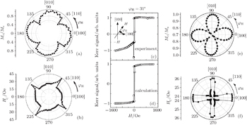
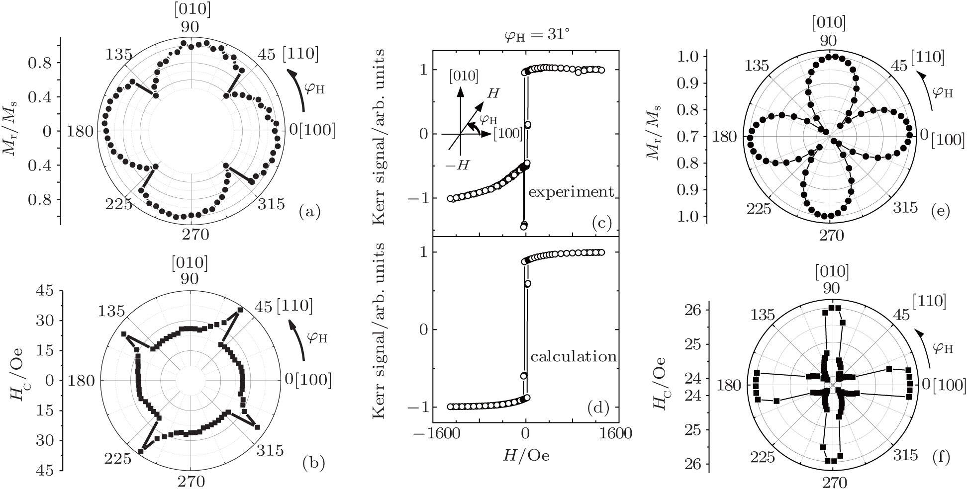
3. Results and discussionThe normalized remanence and coercivity are derived from the hysteresis loops measured by sample rotation with longitudinal Kerr geometry. As respectively shown in Figs. 1(a) and 1(b), the angular dependences of normalized remanence Mr/Ms and coercivity HC on field orientation clearly verify the in-plane four-fold symmetry for Fe/MgO (001) thin film. However, the measured values of both normalized remanence and coercivity appear to be conspicuously different at the equivalent position from the hard axis. The origin of this abnormal phenomenon is that for the hysteresis loops measured around the hard axis their two branches corresponding to the magnetization reversal processes are asymmetric. Figure 1(c) shows the hysteresis loop measured at φH = 31°, where φH is the angle between the applied positive field and the Fe [001] axis. Since the value of the normalized remanence is larger than 1 when we use the value of the Kerr signal at the saturation field as a maximum and a minimum for normalization separately, we ascribe the asymmetry in hysteresis loops to the consequence of the quadratic magneto–optic effect on the shape of hysteresis loop,[18] which is obvious on the Kerr signal at the low field when the value of the transversal magnetization component is large and has no effect on the magnetization reversal process.[17,18] In the following, we will discuss how to clarify the consequence of the quadratic magneto–optic effect from the measured Kerr signal and show the detailed method. However, we first give the calculated hysteresis loop at φH = 31° as shown in Fig. 1(d), in which the normalized value is determined by the linear magneto–optic effect. As clearly shown, the asymmetry in the hysteresis loop, caused by the contribution of the quadratic magneto–optic effect will greatly change the value of the normalized remanence and coercivity. By using the same method, we modify the polar plot for the angular dependences of normalized remanence Mr/Ms and coercivity HC on the field orientation without the contribution of the quadratic magneto–optic effect as given in Figs. 1(e) and 1(f). The result indicates that both the normalized remanence Mr/Ms and coercivity HC decrease as the magnetic field rotates to the hard axis and exhibit minima at the hard axis. Moreover, at the equivalent position from the hard axis the values of the normalized remanence and coercivity are comparable.
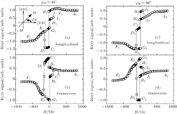
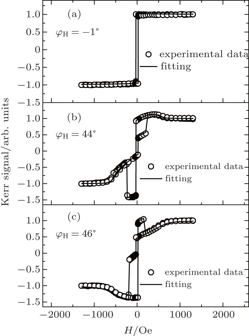
Figure 2 shows the longitudinal and transverse Kerr signals depending on the applied field. The hysteresis loops each include two branches, A–B–C–D–E–F and F–G–H–I–J–A. On account of the magnetocrystalline anisotropy of Fe/MgO (001), the magnetization reversal process takes place via coherent rotation and/or domain wall placement with the magnetic field applied in the Fe (001) plane. Although both coherent rotation and domain wall displacement can be clearly displayed from the longitudinal or the transverse hysteresis loops, integrated investigation of these two orthogonal components helps to determine the direction of the magnetization vector. As shown in Fig. 2(a), at φH = 44°, when the applied field strength decreases from a positive saturated state to zero, the magnetization changes via coherent rotation from the direction of the applied field to the nearest Fe [100] direction, which corresponds to the A1–B1 period. Increasing the negative applied field strength to the first switching field (about −26 Oe, 1 Oe = 79.5775 A·m−1), 90° domains with magnetization orientation close to [0-10] are nucleated and unpinned at the edge of the sample, followed by a speedy 90° domain wall displacement.[21] corresponding to the B1–C1 period. At the section C1–D1, the magnetization proceeds via coherent rotation towards Fe [0-10]. When the negative magnetic field strength increases up to the second switching field (about −210 Oe), the magnetization rotates closely to [-100] by the second 90° domain wall displacement at the D1 − E1 section. Further increasing the negative applied field strength, the magnetization rotates towards the direction of the applied field by a coherent rotation before saturation (E1–F1 stage). In the F1–G1–H1–I1–J1–A1, the change of the magnetization is similar to the A1–B1–C1–D1–E1–F1.[21] The magnetization proceeds with coherent rotation at the stages of F1–G1, H1–I1, and J1–A1, and 90° domain wall displacement takes place at the stages of G1–H1 and I1–J1.
The hysteresis loop in Fig. 2(b) shows that the magnetization reversal process of φH = 46° also occurs by coherent rotation and 90° domain wall displacement. However, the magnetization behaviors are different between at φH = 44° and at φH = 46°. As clearly shown in Figs. 2(c) and 2(d), when the field is reduced from the positive maximum value to zero, the magnetization of φH = 44° proceeds via coherent rotation towards [100] while the magnetization of φH = 46° proceeds via coherent rotation towards [0-10]. This result is compatible with the four-fold magnetocrystalline anisotropy of Fe (001).
In order to verify the above description about the magnetization reversal process and clarify the origin of the asymmetry of the hysteresis loops, a quantitative analysis of the magnetization reversal process is performed by simulating the longitudinal Kerr signal.
Generally, four-fold magnetocrystalline anisotropy is accompanied with a weak uniaxial magnetic anisotropy in the Fe (001) plane. We decompose the energy of uniaxial anisotropy to Fe [100] and Fe [110].[6] The total energy density of the system at the applied field H is given by
where
Ku1 and
Ku2 are the uniaxial magnetic anisotropy constants at Fe [100] and Fe [110] direction, respectively,
K1 is the first-order cubic magnetocrystalline anisotropy constant,
Ms is the saturation magnetization,
H is the applied field strength, and
φM is the angle between the direction of magnetization and Fe [100]. According to the Stoner-Wohlfarth model, the magnetization will rotate to a certain direction so that the total energy density of the system reaches a minimum value. Then equation (
2) can be obtained by differentiating Eq. (
1):
where
l(
φM) is the normalized torque. As indicated by Eq. (
2), the magnitude of
l(
φM) changes with
φH −
φM, which reflects the change of magnetic anisotropy energy.
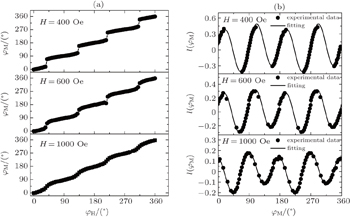
Here, ROTMOKE is employed to determine the anisotropy constants.[27] In order to ensure a coherent rotation process, the applied field should be at least larger than the maximum coercive field in the plane. Figures 3(a) and 3(b) show the direction of the magnetization varying with the direction of the applied field and the angular dependence of the torque curve at different strengths of field. At H = 400 Oe, the direction of the magnetization shows four sudden jumps so that the torque curve is broken down into four intervals because of the four occurrences of 90° domain wall displacement process. Further increasing the applied field to 1000 Oe, the domain wall displacement seems to disappear, and the direction of the magnetization changes with the direction of the field as a result of the coherent rotation process. The magnetic anisotropy constants can be obtained by fitting Eq. (2) to the torque curve under an applied field of 1000 Oe. Using the bulk value of 1.76 × 10⁶ A/m as the saturation magnetization of Fe, the obtained results are Ku1 = 1.6 × 10³ J/m3, Ku2 = 7.5 × 10³ J/m3, and K1 = 5.6 × 10⁴ J/m3.
For fitting the experimental data of the longitudinal Kerr signal, we consider both the linear and the quadratic magneto–optic effect. The formula of the detected normalized light intensity, which is obtained based on the proportional relationship between the output current and the squared modulus of the electric field parallel to the analyzer transmission axis, is as follows:[28]
In Eq. (
3),
ml =
Ml/
Ms,
mt =
Mt/
Ms, with
Ml and
Mt being the magnetization components parallel and perpendicular to the applied field respectively.

is tenable for the magnetization in the plane; superscript or subscript l and t represent the longitudinal and transverse effect;

,

,

, and

, are the complex Fresnel coefficients of light reflected from magnetic films;
[28,29] c.c is the complex conjugate of the expression and * denotes the complex conjugate of Fresnel coefficients;
θp and
θa are the orientations of the polarizer and the analyzer with respect to the incident light plane;

and

are independent of magnetization. Terms

and

both include only a magnetic term proportional to
QMt/
Ms, where
Q is the Voigt magneto–optical parameter and proportional to the magnetization in the ferromagnet.
[28] Terms

and

are proportional to
QMl/
Ms. Term
corresponds to the sum of terms proportional to
QMl/
Ms and

.
According to the geometrical relationship, Ml = Ms cosθ and Mt = Ms sin θ are obtained, where θ = φH − φM is the angle of the positive direction of the applied field with respect to the magnetization vector. Therefore, the expression of normalized detectable light intensity in the longitudinal configuration can be rewritten as

where
α,
β, and
γ are parameters depending on the optic geometry (polarization angle of the incident laser, analyzer angle and incident angle), and the dielectric tensor of the material.
[17,28] For a given optic geometry,
α,
β, and
γ are constants.
According to the minimum energy principle, the orientation of the magnetization φM is always changing with applied field H. The calculated anisotropy constants (Ku1, Ku2, K1) are substituted into Eq. (1) with different H values for given φH so as to obtain the value of θ. Then, we substitute θ into Eq. (4) to calculate the value of normalized light intensity and consequently obtain the hysteresis loops with changing magnetic field. The valves of α = 0.9, β = − 0.06822, γ = − 0.2847 show the best fitting of the simulation to the experimental MOKE hysteresis loops for detecting the longitudinal magnetization component.
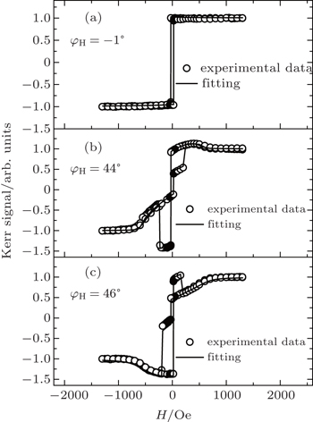
As illustrated in Fig. 4, the coherent rotation of the magnetization is interrupted by the domain wall displacement at the coercive field. The type of domain wall displacement depends on the direction of the magnetic field. When rotating the field at φH = − 1°, the magnetization reversal process takes place via the “l-jump” process (180° domain wall displacement). At φH = 44° and φH = 46°, the magnetization reversal processes occur via the “2-jump” process (90° domain wall displacement). Besides, the branches of hysteresis loops at φH = 44° and φH = 46° appear to be asymmetric apparently due to the transverse magnetization component contribution to the light intensity that is used for detecting the longitudinal magnetization component. Since the value of α is much larger than those of β and γ, the contribution mainly comes from the quadratic magneto–optic term Ml Mt. When the field is applied closely to the hard axis, the magnetization aligns parallelly to the direction of the applied field at the saturation field. The transverse magnetization component Mt (sin θ) is almost equal to zero. As the field decreases towards the first switching field, the magnetization presents the coherent rotation to the perpendicular direction of the field after a 90° domain wall displacement process. In the coherent rotation process, Ml Mt will acquire a maximum value so that asymmetry originating from the conspicuous quadratic magneto–optic effect can be observed in the hysteresis loop. However, when the field is applied closely to the magnetic easy axis, the magnetization reversal process is governed by the 180° domain wall displacement. In the whole magnetization reversal process, the contribution of Ml Mt is small and symmetric hysteresis loops are observed.


 ]
]