


Design of terahertz beam splitter based on surface plasmon resonance transition
[Liu Xiang1, 2, Yang Dong-Xiao1, 2, †,  ]
]
]
|
|


† Corresponding author. E-mail:
According to the resonance transition between propagating surface plasmon and localized surface plasmon, we demonstrate a design of beam splitter that can split terahertz wave beams in a relatively broad frequency range. The transmission properties of the beam splitter are analyzed utilizing the finite element method. The resonance transition between two kinds of plasmons can be explained by a model of coherent electron cloud displacement.
The specific characteristics of surface plasmon (SP) in the terahertz (THz) region of concentrating and guiding waves utilizing subwavelength structures arouse the great interest of many researchers. For decades, applications based on SP have been promoted in various regions, such as waveguide, laser antenna and sensor.[1–5] A beam splitter is an optical device that splits a beam of light into two or more beamlets. In the terahertz region, the design and research of the beam splitter has been conducted for several years. By different methods, a THz beam can be split by different polarizations[6] or wavelengths.[2,7] In the present work, we present a design of beam splitter based on SP resonance transition between propagating surface plasmon (PSP) and localized surface plasmon (LSP), which can split a THz beam, with its optical properties unchanged. By utilizing the finite element method (FEM), the transmission properties of the splitter and effects of SP resonances (both PSP and LSP) are studied. Analysis shows that the resonance transition between PSP and LSP plays a key role in the process of beam splitting. The transition can be explained by a coherent electronic cloud displacement model. The design of the splitter has a relatively broad operating frequency region.
The beam splitter is a centrosymmetric cross structure which is composed of four parallel corrugated metal plates (PCMPs) and a pair of metal blocks engraved with an air loop as shown in Fig.
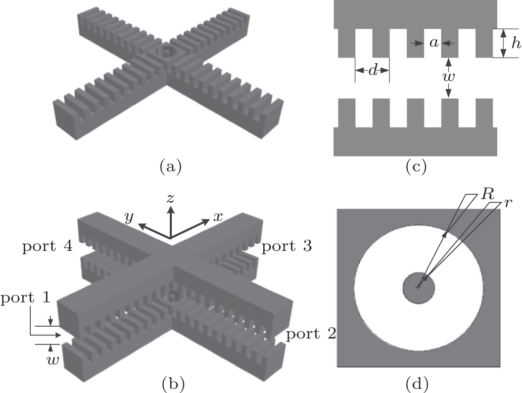 | Fig. 1. (a) Single layer of the splitter, where a metal block is surrounded by four periodic corrugated metal plates; (b) three-dimensional schematic model of the splitter; (c) schematic model of PCMP and its corresponding parameters; (d) top view of the metal block engraved with air loop and its corresponding parameters. |
Surface plasmon (SP) wave (SPW) emerges when an incoming electromagnetic wave excites collective electronic oscillations at the interface of metal/dielectric. According to different properties, the SP can be termed PSP and LSP.[8] For PSP, the SPW is confined and propagates along the surface of metal. In the terahertz region, periodical structures corrugated on a metal surface are needed for momentum matching. For the LSP, the charge density oscillations are present around metallic subwavelength structures and non-propagating. In contrast with the PSP, the LSP resonance mainly depends on the size and shape of the metallic structure while the PSP mainly depends on lattice constant.[9,10]
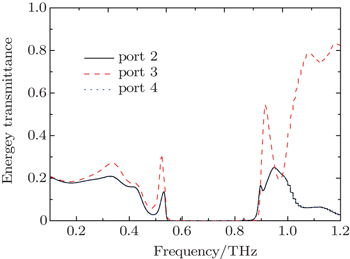
As is well known, the SP resonance is triggered by transverse magnetic (TM) wave,[11] thus the incident wave is in the TM mode with its wave vector straight along the x axis. The metal was set as a perfect electric conductor (PEC) in simulations since the dielectric constant of metal is very large in the terahertz region which approaches to that of PEC.[12,13] The energy transmittance spectrum of the splitter is first simulated and plotted in Fig.
 | Fig. 2. Energy transmittance spectra of ports 2 (solid), 3 (dashed) and 4 (dotted). |
Figure
Figure
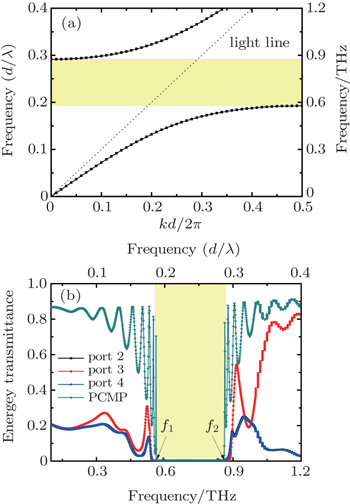
 | Fig. 3. (a) Transmittance spectrum of PCMP and its corresponding dispersion curves; (b) transmittance spectra of PCMP at three output ports of the splitter. |
The SPW is characterized by Ez, thus the role of SP resonance can be well clarified by electric field distributions of Ez as shown in Fig.
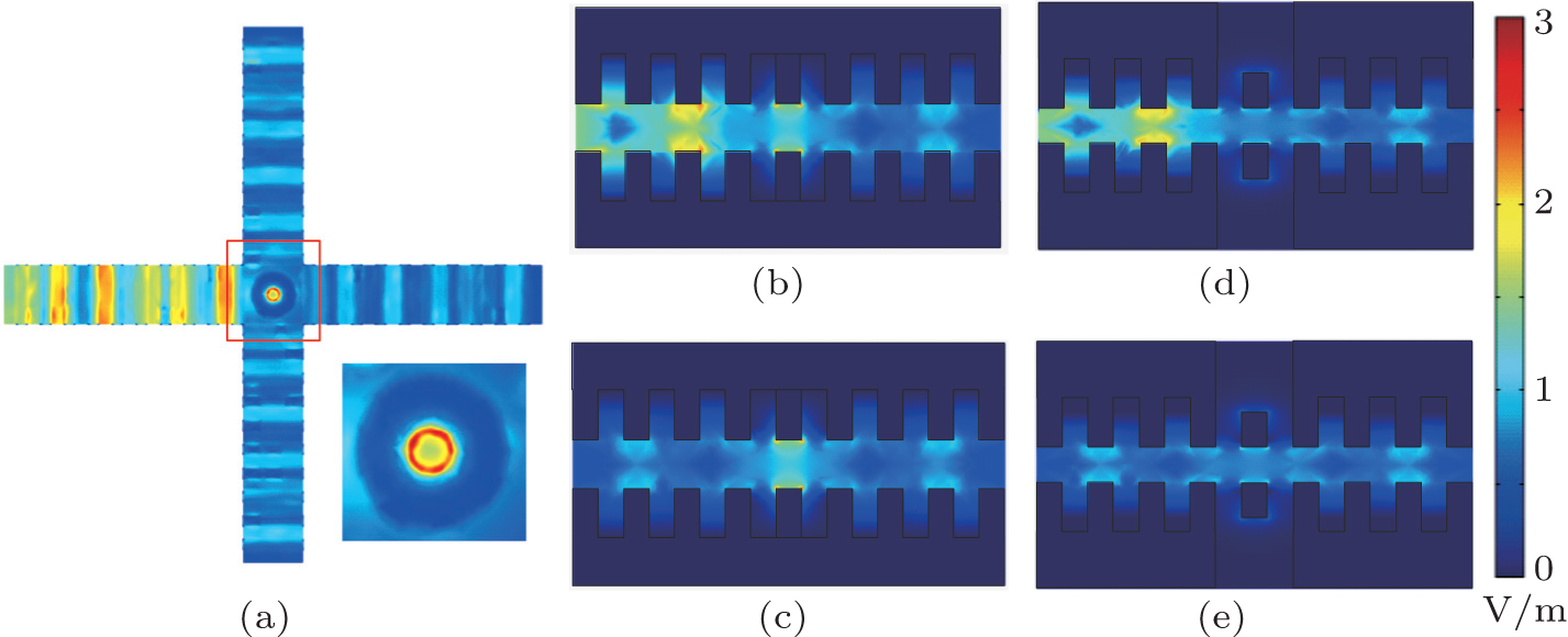 | Fig. 4. Electric field density distributions (f = 0.4 THz) of Ez on cross structure for (a) x–y plane view on the surface of the metal plate, (b) y–z plane view, and (c) z–x plane view across the center of metal blocks. Electric distributions of cross structure with metal cylinder separated from substrate for (d) y–z plane view and (e) z–x plane view across the center of metal blocks. |
Figures
Unlike the PSP, the dispersion relations of LSP were acquired by quasi-static calculation,[8] which contain two modes characterized as longitudinal and transversal modes. The wave-vector direction of the transversal mode is perpendicular to that of the longitudinal mode. The transversal mode has a wave vector direction perpendicular to the input vector which would propagate to ports 2 and 4. The longitudinal mode wave is in the same vector direction as the input wave, which would propagate to port 3. The resonance of LSP leads to the splitting of the THz beam. The whole transmission process is a resonance transition from PSP to LSP and then back to PSP. To clarify the transition between PSP and LSP, the electric field distributions of Ex and Ey are simulated, and the results are shown in Fig.
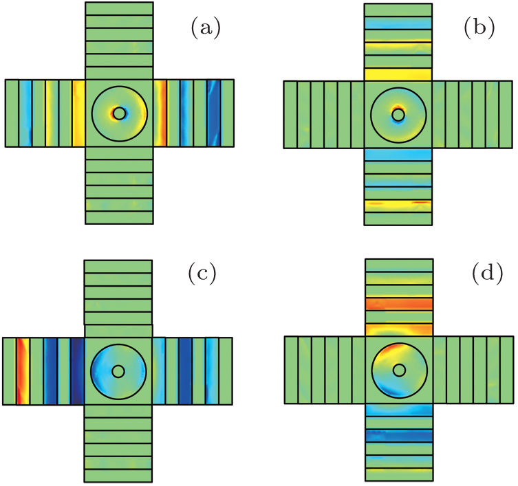 | Fig. 5. Partially magnified electric field distribution of cross structure in the x–y plane: (a) Ex at f = 0.4 THz; (b) Ey at f = 0.4 THz; (c) Ex at f = 0.95 THz; (d) Ey at f = 0.95 THz. |
Although the SPW is characterized by Ez, Ex, and Ey could well exhibit the resonance between PSP and LSP. It can be observed from Figs.
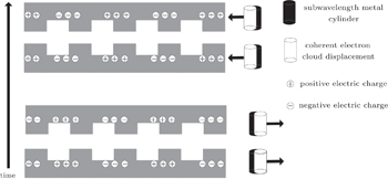
According to the field distributions of Ex and Ey, it can be deduced that the transition between PSP and LSP is due to the charge density oscillation resonance between the cylinder and its outer surrounding metal in the center. Figure
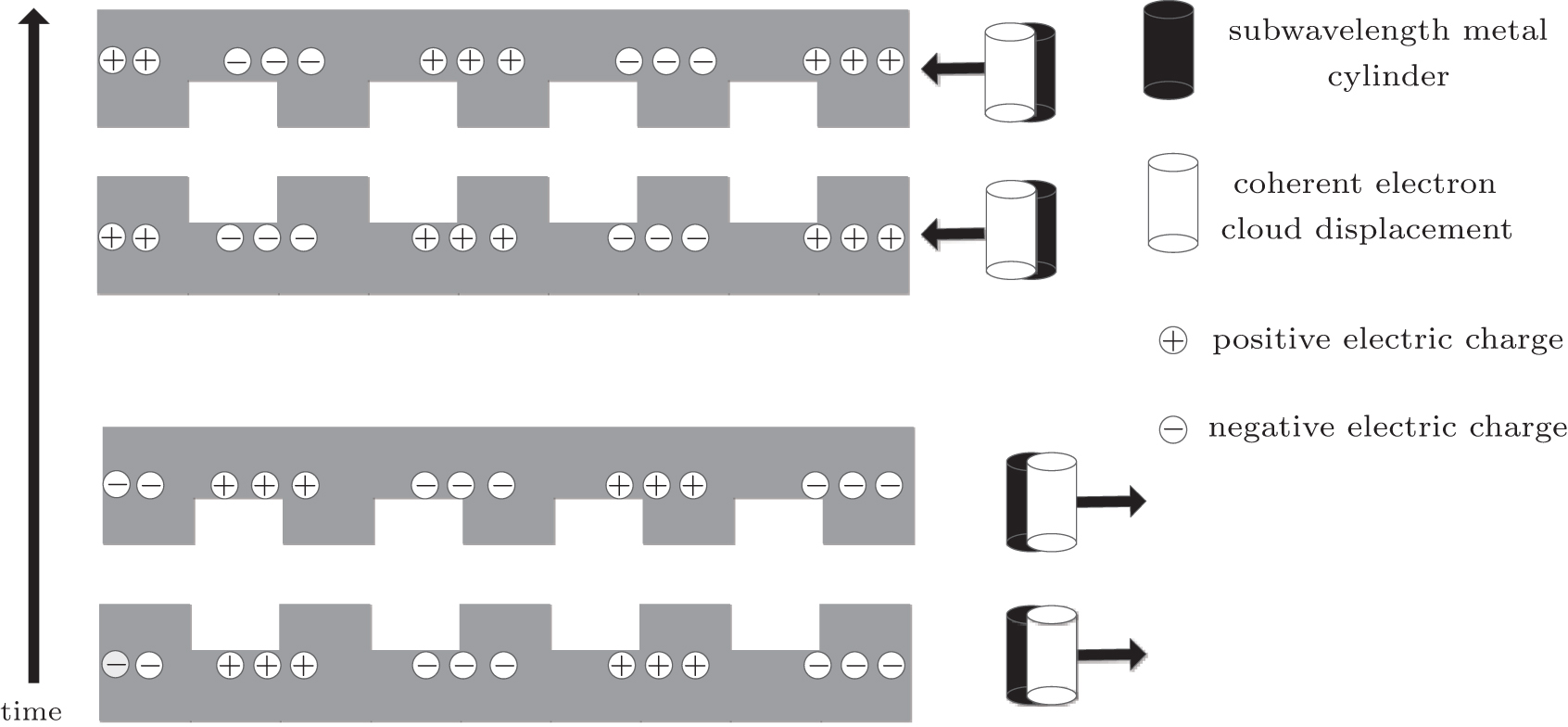 | Fig. 6. Schematic diagrams of resonance transition between PSP and LSP. |
According to the above analyses, it can be deduced that the transmission process of the splitter is as follows: the input THz wave irradiates the PCMP structure and couples as PSP mode, which is confined on the surface of metal plates. When the PSP wave propagates to the outer edge of air loop, the charge density oscillation caused by PSP would induce the charge density oscillation in the metal cylinder and induces the resonance of LSP. The LSP mode contains both longitudinal mode and transversal mode. The longitudinal mode decouples along the direction of the input wave, which is along the x-axis. The transversal mode decouples in the direction perpendicular to the input wave direction which is along the y axis. Then the decoupled waves of both longitudinal and transversal modes couple again as the PSP mode and propagate along the PCMP structure till the output ports. According to the transmittance spectra in Fig.
The influences of geometry parameters on the splitter can be divided into two parts: the parameters of PCMP for PSP resonance and those of the metal block for LSP resonance.
The geometry parameters of PCMP mainly affect the operating frequency range of splitter. The dispersion relation of PSP on PCMP could be calculated by the modal expansion method as[14]
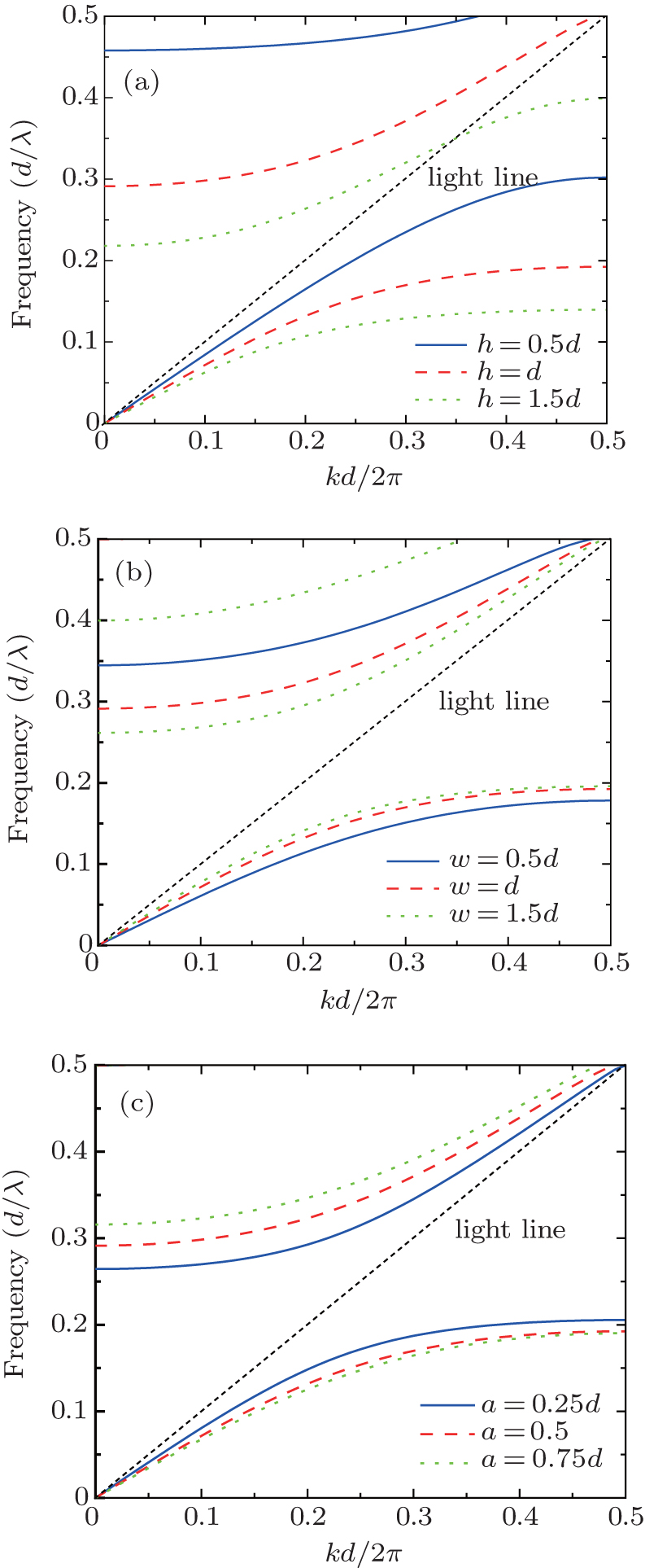 | Fig. 7. Dispersion curves of PCMP with (a) h = 0.5d, 0.75d, and d; (b) w = 0.5d, d, and 1.5d; (c) a/d = 0.25, 0.5, and 0.75. |
It can be observed from Fig.
For different values of w and a/d, a similar dilemma to h occurs that the larger operating frequency will induce weaker confinement of SPW in the lower-frequency region (actually, according to the dispersion curves in Figs.
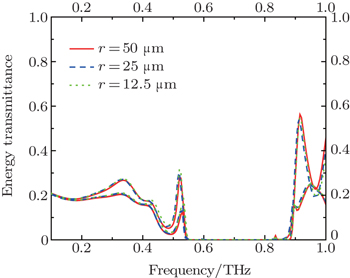
The LSP resonance emerges on the surface of the metal cylinder in the center, thus the resonance can be affected by the cylinder radius r. According to Mie theory, the resonance frequency of LSP is related to plasma frequency by


 | Fig. 8. Transmittance spectra of cross structure (d = 100 μm, a = 50 μm, h = 100 μm, w = 100 μm, R = 75 μm) with r = 50 μm, 25 μm, and 6.25 μm, respectively. |
A broad band beam splitter operating in the terahertz region is presented in this work. With the help of FEM, the transmission properties are analyzed. The process of beam split is based on the resonance transition between PSP and LSP. The input THz wave is coupled as a PSP mode in the PCMP structure, then is converted into the LSP mode when irradiating the metal cylinder. The longitudinal and transversal modes of LSP are decoupled along the perpendicular direction and recoupled as the PSP mode again in the PCMP structure. The operating frequency of splitter is in the lower frequency range corresponding to the PSP resonance range of PCMP. From 0.1 THz to 0.4 THz, output energies of three ports are very close to total energy with a transmission efficiency of 60%. Compared with traditional beam splitters which can split light into two beamlets with different polarizations at a certain frequency, the splitter proposed in this paper provides a way to split a THz wave into three wavelets with the optical characteristics(such as phase and polarization) unchanged and has a relatively broad range of operating frequency.
| 1 | |
| 2 | |
| 3 | |
| 4 | |
| 5 | |
| 6 | |
| 7 | |
| 8 | |
| 9 | |
| 10 | |
| 11 | |
| 12 | |
| 13 | |
| 14 |