Theoretical calculation and experiment of microwave electromagnetic property of Ni(C) nanocapsules
Zhang Dan-Feng1, †, , Hao Zhi-Feng1, ‡, , Zeng Bi1, Qian Yan-Nan2, Huang Ying-Xin2, Yang Zhen-Da2
School of Computer Science and Technology, Guangdong University of Technology, Guangzhou 510006, China
School of Materials and Energy, Guangdong University of Technology, Guangzhou 510006, China


† Corresponding author. E-mail: dfzhang@gdut.edu.cn

‡ Corresponding author. E-mail: zfhao@gdut.edu.cn

Project supported by the Science and Technology Program of Guangdong Province, China (Grant Nos. 2014B010106005, 2013B051000077, and 2015A050502047) and the Science and Technology Program of Guangzhou City, China (Grant No. 201508030018).

Abstract
Abstract

With the combination of the dielectric loss of the carbon layer with the magnetic loss of the ferromagnetic metal core, carbon-coated nickel (Ni(C)) nanoparticles are expected to be the promising microwave absorbers. Microwave electromagnetic parameters and reflection loss in a frequency range of 2 GHz–18 GHz for paraffin-Ni(C) composites are investigated. The values of relative complex permittivity and permeability, the dielectric and magnetic loss tangent of paraffin-Ni(C) composites are measured, respectively, when the weight ratios of Ni(C) nanoparticles are equal to 10 wt%, 40 wt%, 50 wt%, 70 wt%, and 80 wt% in paraffin-Ni(C) composites. The results reveal that Ni(C) nanoparticles exhibit a peak of magnetic loss at about 13 GHz, suggesting that magnetic loss and a natural resonance could be found at that frequency. Based on the measured complex permittivity and permeability, the reflection losses of paraffin-Ni(C) composites with different weight ratios of Ni(C) nanoparticles and coating thickness values are simulated according to the transmission line theory. An excellent microwave absorption is obtained. To be proved by the experimental results, the reflection loss of composite with a coating thickness of 2 mm is measured by the Arch method. The results indicate that the maximum reflection loss reaches −26.73 dB at 12.7 GHz, and below −10 dB, the bandwidth is about 4 GHz. The fact that the measured absorption position is consistent with the calculated results suggests that a good electromagnetic match and a strong microwave absorption can be established in Ni(C) nanoparticles. The excellent Ni(C) microwave absorber is prepared by choosing an optimum layer number and the weight ratio of Ni(C) nanoparticles in paraffin-Ni(C) composites.

1. Introduction

With the development of wireless communications, microwave absorbers are becoming increasingly important for applications in special fields such as silent rooms, radar systems and the military.[14] Nano-materials, as a new type of microwave absorber, have received more and more attention due to their special properties such as surface effect, quantum size effect and small size effect. Until now, microwave nano-absorbers, including nano-metals, nano-alloys, nano-oxides, nano-conductive polymers, the composites of nano-metals and insulation media and so on, have been extensively studied.[510] The potential microwave absorber with nanowire microstructure has a maximum absorption of 8.37 dB when the concentration of the ZnO nanowires is 6%. It has also been reported that the maximum absorption is enhanced up to 12.28 dB when the concentration of ZnO increases 7%.[9] In particular, many efforts have been made to study the nano-materials with the special microstructures. Qiu et al.[10] reported that a cagelike ZnO/SiO2 had been prepared, and the properties of microwave absorption had been studied. It has been found that the maximum absorption of the cagelike ZnO/SiO2 is 10.68 dB at a frequency of 12.79 GHz, and the absorption range is from 10 GHz to 18 GHz under −6.0 dB. Ferrite is a kind of magnetic loss absorbing material with excellent performance.[1113] To solve the heavy mass problem of the traditional spinel ferrite used as a microwave absorber, Huang et al.[12] have synthesized cobalt zinc spinel ferrite nanofiber by the electrospinning method. The microwave absorbing coating containing 15 wt% of Co0.6Zn0.4Fe2O4 ferrite nanofiber showed that the reflection loss is less than −10 dB in the whole X-band. Cho and Kim[13] investigated the microwave absorbing characteristics in grid-shaped rubber composite sheets containing Ag-coated Ni–Zn ferrite particles. In the grid-type absorber with an optimum air cavity volume rate, the reflection loss is 30 dB at 10.5 GHz when a small layer thickness is about 2 mm. The proposed grid-type microwave absorber has advantages in reduced weight in comparison with conventional ferrite composite absorbers.

Carbon-based materials have good dielectric losses, light weights and broadband microwave absorptions. The carbon nanotubes (CNTs) have been investigated in the field of microwave absorption.[1422] Zou et al.[20] reported that multi-walled nanotubes (MWNTs) filled with Ni nanowire have a good microwave absorption. It has been found that the real and imaginary parts of permittivity and permeability in Ni nanowire filled MWNTs composites increase with the increasing of Ni nanowire filled MWNT concentration. The Ni nanowire filled MWNTs/paraffin composite achieves a reflection loss below –10 dB at 6.4 GHz∼11 GHz, and the minimum value is −23.1 dB at 8.0 GHz. The microwave absorption of Ni nanowire filled MWNTs/paraffin composites is attributed to both dielectric and magnetic loss. The microwave-absorbing peaks of composites shift towards low frequencies with an increase in the concentration of Ni nanowire filled MWNTs. Multi-walled carbon nanotubes (MWCNTs)-polyimide matrix can be considered as a high temperature microwave absorbing material with a broadband.[22] When the percentage of MWCNTs is 5%, the −10-dB absorption bandwidth could reach 1.3 GHz, with a microwave absorber thickness of 2.1 mm in a frequency range from 8 GHz to 12 GHz, while the bandwidth below −10 dB is 2.04 GHz with a microwave absorber thickness of 1.7 mm at a temperature of 373 K.

The core (metal)/shell (carbon) microstructure may be an excellent structure for microwave absorption due to the synergistic effect of the material interfaces between the metal cores and the carbon shells. Zhang et al.[23] have reported that Ni(C) nanocapsules have a better electromagnetic match due to the existence of carbon shells and the particular “core/shell” microstructures. According to the transmission line theory, by using the measured relative complex permeability and permittivity, the maximum reflection loss of Ni(C) nanocapsules is calculated to be equal to 32 dB at 13 GHz, and the absorption range below −10 dB is from 11.2 GHz to 15.5 GHz with 2-mm thickness of the microwave absorber. It has been also found that a natural resonance appearing at 5.5 GHz in Ni(C) nanoparticles, which is dominant among microwave absorption properties of Ni(C) nanocapsules, leads to an increased surface anisotropic energy for nanosized particles. Wang et al.[24] reported that according to transmission line theory, a reflection loss of −25 dB in CoNi@C nanocapsules is derived in a frequency range of 5 GHz–17 GHz, and the absorber thickness is between 2.0 mm and 4.8 mm. CoNi@C nanocapsules have the more excellent electromagnetic-wave absorption in a frequency range of 5 GHz–17 GHz. The CoNi@C nanocapsules have dual dielectric relaxation of the permittivity and multiple magnetic resonances of the permeability. Although the current reports on the microwave absorption performance of core (metal)/shell (carbon) microstructure are mostly restricted to simulation by transmission line theory, there are few reports on the experimental absorption. It is important to compare the experimental results with simulation results for evaluating the microwave reflectivity of nano-materials with core/shell microstructure. In the present paper, the experimental absorption of Ni(C) composites is measured and compared with the theoretical simulation result. It is found that the theoretical simulation result can be in good agreement with the measured absorption peak frequency position.

2. Experiment
2.1. Preparation and dispersion of Ni(C) nanoparticles

As for the Ni/C ratio, all the carbon-coated Ni metal nanoparticles were prepared by the carbon arc discharge method in this paper. The carbon arc discharge was generated by discharging between two electrodes with a DC current of 150 A at 60-V voltage under an argon pressure of 10 kPa. The distance between the electrodes was 3 mm–4 mm. An anode of 25 mm in diameter was prepared with a uniform mixture of micron-sized Ni powders (purity 99.9%) and micro-sized graphite powders (purity 99.0%) in a 50% Ni/C weight ratio. The morphology and microstructure of the sample were examined by transmission electron microscopy (TEM), x-ray diffraction (XRD), and x-ray photoelectron spectroscopy (XPS). Ni(C) nanoparticles and sodium dodecyl benzene sulfonate (SDBS), which were mixed according to a certain proportion, were added into a certain amount of deionized water. The mixed solution was refluxed for 30 min at room temperature, and then the precipitates, which were Ni(C) nanoparticles mixed with SDBS, were separated out of the solution. The slurry of Ni(C) nanoparticles were prepared by adding these pre-treated Ni(C) nanoparticles into the anhydrous ethanol. The slurry of Ni(C) nanoparticles were dispersed by methods of electric stirring for 10 min and ultrasonic dispersion for 10 min successively.

2.2. Preparation of the coaxial sample

The outer and inner diameters of each of the toroidal shaped coaxial samples of paraffin-Ni(C) were 7 mm and 3 mm respectively. The coaxial samples were prepared by dispersing uniformly the Ni(C) nanoparticles in a paraffin matrix, and were transparent for an electromagnetic wave. In order to measure the electromagnetic parameters, the coaxial samples were pressed into a cylindrical compact. The system of an AV3618 vector network analyzer was used to measure the electromagnetic parameters.

2.3. Preparation and measurement of the coating samples

Pre-treated Ni(C) nanoparticles, epoxy resin and anhydrous ethanol were used as a filler, matrix and dispersion medium, respectively. The Ni(C) nanoparticles/epoxy resin was prepared by dispersing the slurry of Ni(C) nanoparticles into epoxy resin. These coating samples were painted onto the 180 mm ×180 mm standard aluminium plate, which are shown in Fig. 1, and then samples of microwave absorbing were obtained. The reflection losses were measured by the Arch method which is an important and useful method to evaluate the practical reflectivity of the absorbing material. The AV3618 vector network analyzer was used to measure the reflection losses of the coating samples.

Fig. 1. Microwave absorption plate of Ni (C) mixed epoxy resin (a) and the standard aluminium plate (b).

With the combination dielectric loss of the carbon layer and magnetic loss of the ferromagnetic metal cores, Ni(C) nanoparticles are expected to be promising microwave absorbers. The properties of microwave absorption in carbon-coated nanoparticles can be calculated by reflection loss based on transmit-line theory.[25,26] The measured electromagnetic parameters of paraffin-Ni(C) composites are substituted into the following electromagnetic equations (1)–(5) and the microwave reflectivity of the paraffin-Ni(C) composite can be calculated.

According to the transmission line theory, the input impedance of the layers is Zin(K) (K = 1, 2, …,N). The input impedance of each layer can be calculated from the following formula:

Because at the bottom is a metal plate, Zin(0) = 0 which is the impedance of free space. Zc(K) and γ(K) can be calculated from Eqs. (2) and (3),

where Zc(K) and γ(K) are the characteristic impedance and propagation constant of each layer, respectively, c is the light speed, ω is the angular frequency, ε0 and μ0 are vacuum permittivity and permeability, respectively, εr(K) and μr(K) are relative permittivity and permeability of the K layer absorbing material, respectively.

When the electromagnetic wave is incident vertically on the interface, of which the input impedance through the free space is Z0 = (μ0/ε0)1/2, part of it is reflected, and the rest enters the absorber. The absorber reflection factor is determined by the following formula:

Reflection rate (R) of the N-layer absorbing material is calculated from the following formula:

An optimum designing program for the multilayer absorbing material is compiled by matlab language. The program can transfer the electromagnetic parameters of absorbing materials which are measured by a vector network analyzer, and can process the thickness optimum design of different absorbing materials.

3. Results and discussion
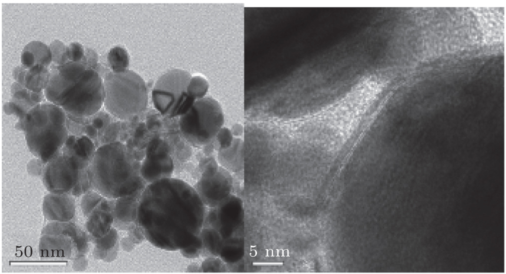
3.1. Characterization of Ni(C) nanoparticles

Figure 2 shows the TEM images of core-shell structured Ni(C) nanoparticles. As for Ni(C) nanoparticles, the magnetic nickel particle acts as a core, and carbon layer, which acts as a shell, is coated evenly on the surface of the nickel nanoparticle. The carbon layer has a high dielectric constant. As shown in Fig. 2, the diameter of the particle is about 20 nm–80 nm, and the thickness of the carbon layer is about 2 nm–3 nm.

Fig. 2. TEM images of the Ni(C) nanoparticles.

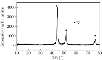
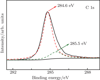
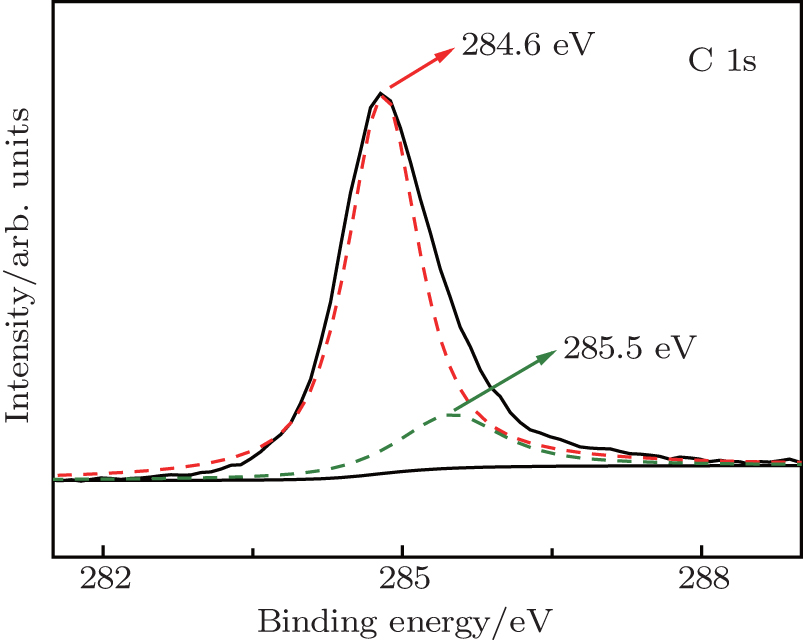
Figure 3 shows the XRD spectrum of the Ni(C) nanoparticles. It can be seen that there are three diffraction peaks in the prepared Ni(C) nanoparticles. Compared with the three standard diffraction peaks of the elemental nickel, neither nickel oxide nor carbides are observed, and the diffraction peaks of the amorphous carbon are very weak. The Ni(C) nanoparticles are composed of the pure carbon and pure metal nickel. Figure 4 shows the variation of intensity with binding energy of the Ni(C) nanoparticles and its fitting curve. The peak at 284.6 eV belongs to 1s electrons of the graphite at the surfaces of Ni(C) nanoparticles. The peak at 285.5 eV belongs to 1s electrons of graphite at the interface between graphite and Ni in the Ni(C) nanoparticles.

Fig. 3. X-ray diffraction patterns of Ni(C) nanoparticles.
Fig. 4. XPS patterns of Ni(C) nanoparticles.

Figure 5 is the hysteresis loop of Ni(C) nanoparticles. It can be seen that the intensity of saturation magnetization (Ms) is 40.339 emu/g, the intensity of remanence (Mr) is 8.147 emu/g, and the coercive force (Hc) is 61 Oe (1 Oe = 79.5775 A·m−1) when the test temperature is equal to 304 K.

Fig. 5. Hysteresis loops of Ni(C) nanoparticles at T = 304 K.
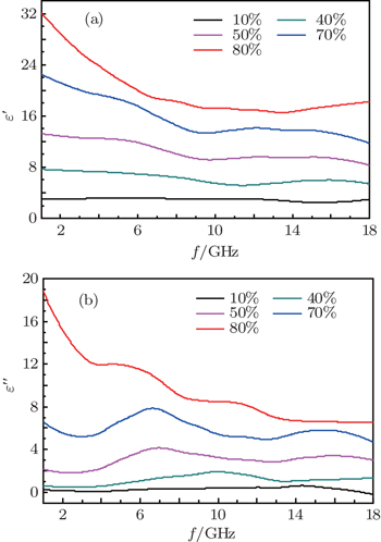
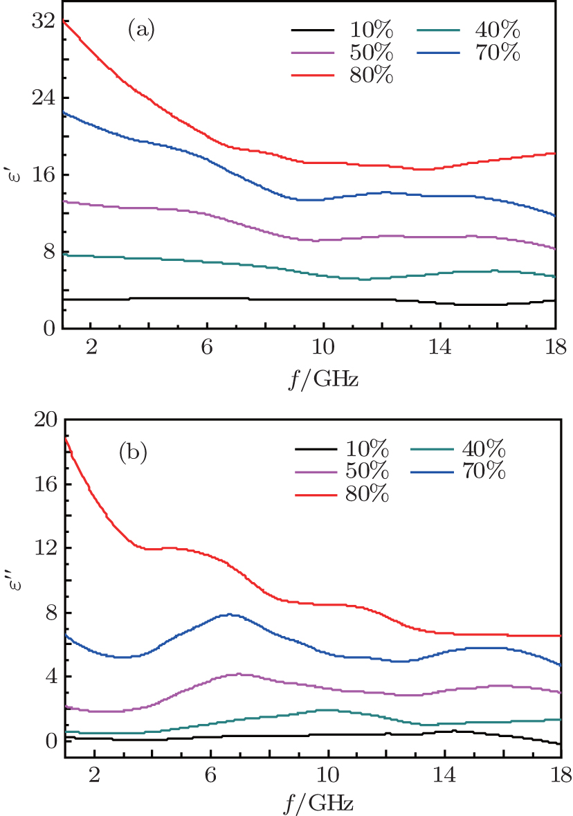
3.2. Relative complex permittivity and permeability of paraffin-Ni(C) composites

Figure 6 shows the variations of relative complex permittivity of paraffin-Ni(C) composites with frequency, measured in a frequency range of 2 GHz–18 GHz for the weight ratios of Ni(C) in paraffin-Ni(C) composites of 10 wt%, 40 wt%, 50 wt%, 70 wt%, and 80 wt%, respectively. Since the complex permittivity of paraffin is small, the complex permittivity of paraffin-Ni(C) increases gradually with the increase of the weight ratio of Ni(C) nanoparticles. It is shown that there is no change in the relative complex permittivity of paraffin-Ni(C) composites when the weight ratio of Ni(C) is less than 40 wt%. However, above 50 wt%, both the real part (ε′) and imaginary part (ε″) of each relative complex permittivity decreases with the increase of frequency. When the weight ratio of Ni(C) nanoparticles is equal to 80 wt%, the real part (ε′) value of relative complex permittivity declines sharply from 32 to 20 in a frequency range from 2 GHz–18 GHz.

Fig. 6. Variations of (a) the real part and (b) the imaginary part of the relative complex permittivity of paraffin-Ni(C) wax composites with frequency for different percentages of Ni(C) in composites.

According to the loss mechanism of absorbing materials for the electromagnetic wave, absorbing materials can be divided into two kinds of materials: the dielectric medium and magnetic medium. The dielectric medium type of absorbing material, which produces electric polarization, absorbs electromagnetic wave energy under the action of electromagnetic field (dielectric loss). Likewise, the magnetic medium type of absorbing material, which produces magnetic polarization, absorbs electromagnetic wave energy under the action of an electromagnetic field (magnetic loss), such as magnetic hysteresis, domain-wall displacement, natural-resonance and eddy-current loss. The Ni(C) nanoparticle is a nanocapsule composite with the shell of a dielectric loss type and the nucleus of a magnetic loss type, and may establish a suitable electromagnetic matching in the microstructure for electromagnetic wave absorption in the gigahertz range. Previous reports have indicated that the surface-anisotropy field in the FeNi(C) nanoparticles is larger than that in the FeNi nanoparticles, which leads to a higher natural-resonance frequency.[27] The same phenomenon has been found in other nanocapsules.[2830]

Some similar fluctuation peaks in the ε″ curves of the Ni(C) nanoparticles are dielectric loss peak (ε″) and attributed to various polarizations. The maximum imaginary part value of relative complex permittivity (ε″) is 19 at 2 GHz. Han et al.[31] reported a similar permittivity spectrum of the carbon-encapsulated FeCo system. Considering the special core/shell microstructure of the Co(C) nanoparticles, a reasonable explanation for observed permittivity curves is that the dipole polarization is dominant at a higher frequency and the space charge polarization plays an important role at a lower frequency.[24,32,33] Similar observations were previously reported in carbon-encapsulated iron nanoparticles.[6]

On the other hand, according to the free electron theory, ε ≈ 1/2πε0ρ f, where ρ is the electrical resistivity.[23] Obviously, low ε″ corresponds to high electrical resistivity. It can be concluded that the electrical resistivity of Ni(C) composites is higher than that of nano-nickel (ρ ∼ 10−3 Ω·cm) due to capsuled carbon (ρ ∼ 10−1 Ω·cm). The protective carbon shells on the surface of Ni nanoparticles can also effectively disperse Ni(C) nanoparticles in paraffin[31,32] so that the perfect performance of Ni(C) composites can be realized.

It is proposed that the core/shell microstructure of the Ni(C) nanoparticles can improve the microwave absorption of nano-carbon particles. The orientation (dipole) polarization and space charge polarization (interfacial polarization) are considered as relaxation polarization and produced larger absorption in the measured frequency range of 2 GHz–18 GHz. The interfacial polarization is also believed to give Co(C) strong dielectric loss, which has been proved in previous work.[28,33,34] The space charge polarization (interfacial polarization) often occurs in an inhomogeneous medium, such as the interface between the core and the shell. Actually, grain boundary, phase boundary and impurity defects can also become an obstacle to the free charge movement, so free charge accumulation is produced and space charge polarization is formed. When Ni(C) is subjected to an electromagnetic field, the space charge polarization occurs at the interface between the amorphous carbon shell and the inner nickel core.

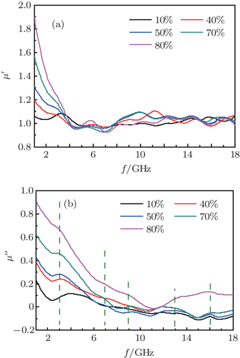
The curves of relative complex permeability in the paraffin-Ni(C) composites at frequencies ranging from 2 GHz to 18 GHz are shown in Fig. 7. The weight percentages of Ni(C) in paraffin-Ni(C) composites are 10 wt%, 40 wt%, 50 wt%, 70 wt%, and 80 wt%, respectively. The relative complex permeability of the paraffin-Ni(C) composite includes the real (μ′) and imaginary (μ″) parts. When the weight percentage of Ni(C) in paraffin-Ni(C) composite is low, the real and imaginary parts of the permeability are small. As the weight percentage of Ni(C) increases, the real and imaginary parts of magnetic permeability increase.

Fig. 7. Plots of (a) the real part and (b) imaginary part of relative complex permeability of paraffin-Ni(C) wax composites versus frequency for 10 wt%, 40 wt%, 50 wt%, 70 wt%, and 80 wt% Ni(C) in composites.

As shown in Fig. 7, the change of permeability at low frequency is more obvious than that at high frequency. When the weight percentage of the Ni(C) nanoparticles is equal to 80 wt%, the values of the real part (μ′) of the relative complex permeability decline from 1.9 to 1.0 in a frequency range of 2 GHz–18 GHz and the μ′ maximum values reach up to 1.9. It is believed that the natural-resonance has strong magnetic loss, resulting in enhanced microwave absorption of Ni(C) nanoparticles. Some other effects contributing to magnetic loss, such as magnetic hysteresis, domain-wall displacement and eddy-current loss, are relatively weak in the Ni(C) nanoparticles. The hysteresis loss is negligible due to the applied microwave field being weak.[25,35] Because the sizes of the ferromagnetic metal nanoparticles and ferromagnetic metal/C nanoparticles are much lower than the skin depth (∼ 1 μm) and the frequency is in a gigahertz range, the contribution of domain-wall displacement can be excluded.[24,35] Therefore, the magnetic loss in the present Ni(C) nanoparticles is caused mainly by the natural- resonance. The imaginary part of complex permeability (μ″) is related to the natural-resonance frequency. The peaks of natural-resonance exhibit broad multi-resonance peaks in a range of 2 GHz–18 GHz, which implies that the natural-resonance occurs in Ni(C) nanoparticles. The frequency positions marked in Fig. 8 are 3, 7, 9, 12.5, 16 GHz, respectively, which are also described similarly in previous papers about graphite-coated FeNi nanoparticles[27] and graphite-coated Fe nanoparticles.[30]

Fig. 8. Plots of (a) dielectric loss tangent and (b) magnetic loss tangent of 50-wt% Ni(C) nanoparticles in composites versus frequency.

In the Ni(C) nanoparticles, the inner nickel cores are separated by the outer carbon shell, so that the direct exchange interactions between magnetic metallic nickel cores are negligible, and the dipolar interaction is the main effect.[25,36] Without the protection of the carbon shell, the direct contact between the metallic nickel cores would take place, and the resulting eddy current would lead to the decrease of μ′ at a lower frequency.[26] The carbon shells between the nickel nanoparticles act as a barrier that effectively reduces the effect of the eddy current in the GHz frequency range. As mentioned previously, Ni(C) has a high electric resistivity, and the eddy current loss is reduced due to the outer carbon shells.[35,37] The Ni(C)/paraffin composite is mainly due to natural resonance instead of magnetic hysteresis, domain-wall displacement, and eddy current loss.

The relationship between the dielectric loss tangent (tanθ) and the frequency of paraffin-Ni(C) composites with 50-wt% Ni(C) nanoparticles is shown in Fig. 8(a). The dielectric loss tangent is also named loss factor and can be calculated from the equation: tanθ = ε″/ε′. As shown in Fig. 9(a), the dielectric loss tangent (tanδ) of the paraffin-Ni(C) composites increases from 0.175 at a frequency of 0 GHz to 0.45 GHz at a frequency of 18 GHz. A peak of dielectric loss tangent is observed at about 7 GHz–8 GHz. Figure 9(b) displays the relationship between the magnetic loss tangent (tanδ) and frequency of paraffin-Ni(C) composites with 50-wt% Ni(C) nanoparticles. The magnetic loss tangent can be obtained from the equation: tanδ = μ″/μ′. A peak of magnetic loss tangent is found to be at about 13 GHz, suggesting that there is a natural resonance at a frequency of 13 GHz. This is also an indication that some magnetic losses occur in paraffin-Ni(C) composites.

Fig. 9. (a) Curves of reflection loss versus frequency for 40 wt%–80 wt% Ni(C) in composites coating with 3-mm thickness, and (b) curves of reflection loss versus frequency for 50 wt% Ni(C) in composites coating with 2 mm–4 mm thickness.
3.3. Theoretical simulation and practical measurement of reflection loss for paraffin-Ni(C) composites

According to the theoretical simulation, the curves of the reflection rate in paraffin-Ni(C) composites with 40% −80% wt% Ni(C) nanoparticles are shown in Fig. 9(a). The thickness of paraffin-Ni(C) composites is about 3 mm. It can be seen that a peak of reflection rate in paraffin-Ni(C) composites with Ni(C) nanoparticles of 50% weight percentage is obtained to be −60 dB at 8 GHz. The absorption frequency under −10 dB (bandwidth) is over 5 GHz. When the weight percentage of Ni(C) nanoparticles continues to increase, absorption peaks shift towards the low frequency. Therefore, the combination of dielectric loss and magnetic loss has an excellent absorption effect.

Based on the theoretical simulation, the reflection rate curves of paraffin-Ni(C) composites with 50% Ni(C) nanoparticles and the thickness values of 2, 3, and 4 mm, respectively, are shown in Fig. 9(b). As for the thickness of 2 mm, there is a reflection rate peak of −32 dB at 12.5 GHz in the reflection rate curve and the bandwidth under −10 dB is about 8 GHz. When the thickness is 3 mm, the reflection rate peak is found to be −60 dB at 8 GHz, and the bandwidth under −10 dB is about 5 GHz. With the decrease of thickness of paraffin-Ni(C) composites, the absorption peaks shift towards high frequency.

Generally, the excellent microwave absorbers result from the efficient complementarity between the relative complex permittivity and permeability of the material. The existence of carbon shells and magnetic Ni cores for Ni(C) nanoparticles is favourable to setting up an excellent electromagnetic match. Based on the above measured data of relative complex permeability and permittivity, a simulation of reflection loss is carried out with 2-mm thickness microwave absorbing coating consisting of paraffin-Ni(C) composites and calculated theoretically the reflection loss according to the transmit-line theory.[38,39] Figure 10(b) shows the simulated results, indicating that the maximum theoretical reflection loss reaches −32 dB at about 12 GHz, and the absorption frequency range under −10 dB is over 7 GHz. Therefore, it is convincing that the Ni(C) can improve the electromagnetic match and obtain strong microwave adsorption due to the particular structure of Ni(C).

Fig. 10. Practical reflection loss versus frequency for 2-mm-thick Ni(C)/resin composites coating.

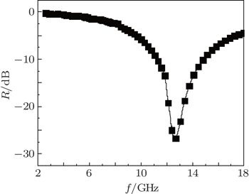
To further prove theoretical simulation of the excellent microwave absorption in Ni(C) nanoparticles, epoxy resin-Ni(C) microwave absorption is prepared by dispersing the Ni(C) nanoparticles in epoxy resin and painting them onto the aluminum plate. The coating thickness is 2 mm and the weight percentage of Ni(C) is 50 wt%. As shown in Fig. 10, the maximum practical reflection loss reaches −26.73 dB at 12.7 GHz, and the absorption range under −10 dB is from 11.2 GHz to 14.8 GHz. The measured absorbing peak is close to the simulated result, indicating that Ni(C) nanoparticles indeed have an excellent microwave absorption.

4. Conclusions and perspectives

In this study, we can see that the relative complex permittivity and permeability of paraffin-Ni(C) composites increase with the increase of the weight percentage of Ni(C) in paraffin-Ni(C) composites. The paraffin-Ni(C) composites exhibit excellent microwave absorption, which is attributed to the combination of the dielectric loss of shells and the magnetic loss of cores arising from the core and shell microstructure of Ni(C) nanoparticles. The absorption of paraffin-Ni(C) composites is mainly due to natural resonance instead of magnetic hysteresis, domain-wall displacement, and eddy current loss.

As for the 50-wt% Ni(C) nanoparticles in paraffin-Ni(C) composites, the simulated results indicate that the maximum theoretical reflection loss reaches −60 dB at 8 GHz and the absorption frequency range under −10 dB is over 5 GHz for the thickness of 3 mm. When the thickness decreases to 2 mm, the maximum theoretical reflection loss is observed to be −32 dB at 12.5 GHz, suggesting that reducing the thickness of the paraffin-Ni(C) composite will be beneficial to the shift of the absorption peak toward the high frequency. The experimental results show that the maximum reflection loss is −26.73 dB at 12.7 GHz and the absorption bandwidth less than −10 dB is 4 GHz with an absorption layer of 2-mm thickness. Theoretical simulation results are well consistent with the measured absorption peak frequency position. The excellent Ni(C) nanoparticles microwave absorber can be prepared by choosing an optimum layer number and weight percentage of Ni(C) nanoparticles in the composites.

Reference
1Yu Z HTian J RSong Y R 2014 Chin. Phys. 23 094206
2Liu G QYing H P 2014 Chin. Phys. 23 050502
3Zhao S MZhuang P 2014 Chin. Phys. 23 054203
4Ramasubramaniam RChen JLiu H Y 2003 Appl. Phys. Lett. 83 2928
5Zhang X FDong X LHuang H 2007 Acta Mater. 55 3727
6Zhang X FDong X LHuang H 2007 J. Phys. D: Appl. Phys. 40 5383
7Zeng MLiu JYue MYang H ZDong H RTang W KJiang HLiu H FYu R H2015J. Appl. Phys.117B527
8Zuo H PGe S HWang Z K 2008 IEEE Trans. Magn. 44 3111
9Liao Z QNie YRen W Y 2010 IEEE Magn. Lett. 1 5000204
10Qiu JGong R ZFeng Z K 2010 J. Alloys Compd. 496 467
11Huang X GZhang JLiu Z HSang T YSong BZhu H LWong C P 2015 J. Alloys Compd. 648 1072
12Huang X GZhang JXiao S RChen G S 2014 J. Am. Ceram. Soc. 97 1363
13Cho H SKim S S2015J. Appl. Phys.117311
14Cao M SShi X LFang X YJin H BHou Z LZhou W 2007 Appl. Phys. Lett. 91 203110
15Zhang H YZeng G XYing G 2009 J. Appl. Phys. 105 054314
16Zhan Y QZhao RLei Y J 2011 J. Magn. Magn. Mater. 323 1006
17Tong G XWu W HHua Q A 2011 J. Alloys Compd. 509 451
18Ye ZLi ZRoberts J A 2010 J. Appl. Phys. 108 054315
19Chen M DJie X HZhang H Y 2014 Acta Phys. Sin. 63 066103 (in Chinese)
20Zou T CLi H PZhao N G 2010 J. Alloys Compd. 496 L22
21Zhao D LZhang J MLi X 2010 J. Alloys Compd. 505 712
22Wang H YZhu D MZhou W CLuo F 2015 Chem. Phys. Lett. 633 223
23Zhang X FDong X LHuang HLiu Y YWang W NZhu X GLv BLei J P 2006 Appl. Phys. Lett. 89 053115
24Wang HDai Y YGong W JGeng D YMa SLi DLiu WZhang Z D 2013 Appl. Phys. Lett. 102 223113
25Naito YSuetake K 1971 IEEE Trans. Microwave Theory Tech. 19 65
26Yusoff A NAbdullah M HMansor A AHamid S A A 2002 Appl. Phys. 92 876
27Liu X GOu Z QGeng D YHan ZJiang J JLiu WZhang Z D 2010 Carbon 48 891
28Liu X GJiang J JGeng D YLi B QHan ZLiu W 2009 Appl. Phys. Lett. 94 053119
29Liu X GLi BGeng D YCui W BYang FXie Z G 2009 Carbon 47 470
30Liu X GOr S WSun Y PLi W HHe Y ZZhu G HJin C GYan QLv Y HHo S LZhao S S 2013 J. Alloys Compd. 548 239
31Han ZLi DWang HLiu X GLi JGeng D Y 2009 Appl. Phys. Lett. 95 023114
32Liu X GGeng D YShang P JMeng HYang FLi B 2008 J. Phys. D: Appl. Phys. 41 175006
33Sun Y PLiu X GFeng CFan J CLv Y HWang Y R 2014 J. Alloy Compd. 586 688
34Wu J HKong L B 2004 Appl. Phys. Lett. 84 4956
35Liu J RItoh MHorikawa TMachida KSugimoto SMaeda T 2005 J. Appl. Phys. 98 054305
36Che R CZhi C YLiang C YZhou X G 2006 Appl. Phys. Lett. 88 033105
37Zhang D FXu F XLin JYang Z DZhang M 2014 Carbon 80 103
38Che R CPeng L MDuan X FChen QLiang X L 2004 Adv. Mater. 16 40
39Zhang X FDong X LHuang HLiu Y YWang W NZhu X G 2006 Appl. Phys. Lett. 89 053115