

Improved performance of polymer solar cells by using inorganic, organic, and doped cathode buffer layers
[Wang Taohong1, Chen Changbo1, Guo Kunping2, Chen Guo2, †,  , Xu Tao2, 3, ‡, , Wei Bin2]
, Xu Tao2, 3, ‡, , Wei Bin2]
|
|


† Corresponding author. E-mail:
‡ Corresponding author. E-mail:
Project supported by the National Natural Science Foundation of China (Grant No. 61204014), the “Chenguang” Project (13CG42) supported by Shanghai Municipal Education Commission and Shanghai Education Development Foundation, China, and the Shanghai University Young Teacher Training Program of Shanghai Municipality, China.
The interface between the active layer and the electrode is one of the most critical factors that could affect the device performance of polymer solar cells. In this work, based on the typical poly(3-hexylthiophene):[6,6]-phenyl C61-butyric acid methyl ester (P3HT:PCBM) polymer solar cell, we studied the effect of the cathode buffer layer (CBL) between the top metal electrode and the active layer on the device performance. Several inorganic and organic materials commonly used as the electron injection layer in an organic light-emitting diode (OLED) were employed as the CBL in the P3HT:PCBM polymer solar cells. Our results demonstrate that the inorganic and organic materials like Cs2CO3, bathophenanthroline (Bphen), and 8-hydroxyquinolatolithium (Liq) can be used as CBL to efficiently improve the device performance of the P3HT:PCBM polymer solar cells. The P3HT:PCBM devices employed various CBLs possess power conversion efficiencies (PCEs) of 3.0%–3.3%, which are ca. 50% improved compared to that of the device without CBL. Furthermore, by using the doped organic materials Bphen:Cs2CO3 and Bphen:Liq as the CBL, the PCE of the P3HT:PCBM device will be further improved to 3.5%, which is ca. 70% higher than that of the device without a CBL and ca. 10% increased compared with that of the devices with a neat inorganic or organic CBL.
Organic solar cells (OSCs) have attracted increasing interest due to their advantages of easy processing, low-cost, high-performance, compatibility with flexible substrates, and use of abundant organic materials.[1–7] It has been regarded as one of the most potential green energy technologies to resolve the increasing energy problems worldwide.[8,9] Recently, rapid development has been achieved for the research of OSC, and the power conversion efficiency (PCE) of OSC has commonly reached 3%–8% in most laboratories,[10–15] while a few have obtained PCE over 10%.[16–18] The device performances of OSCs are mainly determined by the OSC materials, which include not only the donor and acceptor materials, but also the interface and electrode materials.
Conventional OSC devices are composed of a photoactive layer between an indium tin oxide (ITO) anode and a low work function metal cathode. The photoactive layer is formed by the combination of organic donor and acceptor materials, which absorbs solar light and converts photons into charge carriers. The interface material between the active layer and the electrodes plays a key role in charge extraction from the photoactive layer and then the collection to the respective anode and cathode.[19] When the top metal electrode is thermally evaporated on the photoactive layer, the reactive hot metal atoms can lead to chemical interaction at the interface and diffusion into the photoactive layer, which will result in excition quenching and/or a barrier to charge extraction. Inserting a cathode buffer layer (CBL) between the photoactive layer and the top metal cathode is a common way to mitigate the damage from the evaporation of metal onto the photoactive layer.[20] The use of a CBL with a low work function or shallow lowest unoccupied molecular orbital (LUMO) level can efficiently improve the device performance of OSC due to the enhancement of the internal electric field and the reduced carrier defects and traps at the active layer/Al interface.[4,5] Additionally, the CBL can act as both optical spacer and exciton blocking layer.[21] Up to now, the efficient CBL in OSC is still limited to several materials, such as LiF,[22] ZnO,[23] and BCP.[24–26] Thus, it is necessary to develop new materials as the CBL to improve the performance of OSC devices.
In this work, to explore more efficient CBL materials for high-performance OSCs, various inorganic and organic materials commonly used as the electron injection layer in an organic light-emitting diode (OLED), including LiF, Cs2CO3, ZnS, 1,3,5-tris(2-N-phenylbenzimidazolyl) benzene (TPBi), bathophenanthroline (Bphen), and 8-hydroxyquinolatolithium (Liq), are employed as CBLs between the photoactive layer and the top metal electrode in the poly(3-hexylthiophene):[6,6]-phenyl C61-butyric acid methyl ester (P3HT:PCBM) polymer solar cells. Our results demonstrate that all of the devices with various CBLs exhibit much better device performance than those without CBL.
All of the materials used in this work were commercially purchased and used as received. The blend solution of P3HT:PCBM was prepared as follows: 20 mg P3HT and 20 mg PCBM were mixed and dissolved in 1 mL o-dichlorobenzene, then the blend solution was stirred for 24 h and filtered through a 0.2 μm filter before use.
As shown in Fig.
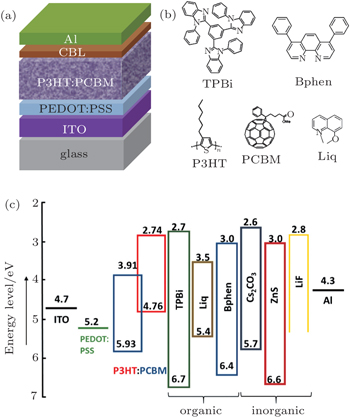
 | Fig. 1. (a) Device structure of P3HT:PCBM polymer solar cell. (b) Molecular structures of P3HT, PCBM, TPBi, Bphen, and Liq. (c) Energy-level diagram of materials under investigation. |
The current density–voltage (J–V) characteristics were measured using a programmable source meter (Keithley 2400) under illumination of 100 mW/cm2 from a solar simulator with AM 1.5G simulated solar spectrum. The external quantum efficiency (EQE) spectra of the devices were measured under standard measurement conditions on a 7-SCSpec solar cell measurement system manufactured by 7-STAR Co. All the measurements were performed in air under ambient conditions without device encapsulation.
Atomic force microscopy (AFM) images were collected in air on a Veeco AFM using a tapping mode. The films for AFM measurement were prepared under the same conditions for fabricating the devices to enable accurate comparisons.
To study the effect of the CBL on the device performance of P3HT:PCBM polymer solar cells, we fabricated and characterized the polymer solar cells based on the device structure of ITO/PEDOT:PSS/P3HT:PCBM/CBL/Al. In the device, the active layer is P3HT:PCBM, and PEDOT:PSS is adopted as the anode buffer layer. For comparison, the same ITO/PEDOT:PSS anode was employed in all of the devices. The P3HT:PCBM photoactive layer was fabricated by spin-coating the P3HT:PCBM solution followed by slow drying and thermal annealing.[27] A P3HT:PCBM device without any CBL was also fabricated as the reference. All of the CBL materials investigated in this work, including LiF (0.3 nm), Cs2CO3 (0.3 nm), ZnS (4 nm), TPBi (4 nm), Bphen (4 nm), Liq (1 nm), Bphen:10% Cs2CO3 (4 nm), and Bphen:10% Liq (4 nm), were thermally evaporated onto the P3HT:PCBM layer in a high-vacuum chamber. Molecular structures of P3HT, PCBM, TPBi, Bphen, and Liq are shown in Fig.
Three inorganic materials LiF, Cs2CO3, and ZnS were used as the CBL in the P3HT:PCBM device in this work to improve the device performance, and the relative device parameters are summarized in Fig.
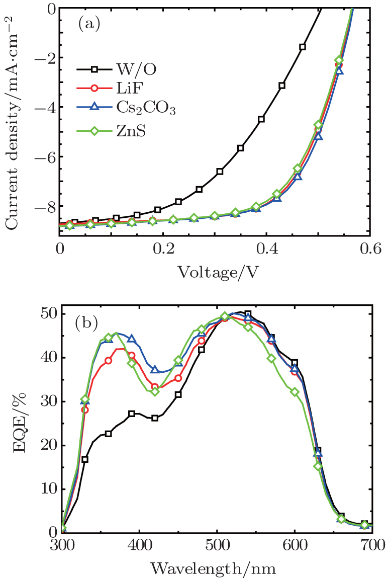 | Fig. 2. Comparison of (a) the J–V characteristics under 100 mW/cm2 illumination of AM1.5G solar spectrum, and (b) the EQE spectra of the P3HT:PCBM devices with various inorganic CBLs with that of the P3HT:PCBM device without a CBL. |
Figure
| Table 1. Device performance of the P3HT:PCBM devices with various inorganic CBLs. Every parameter in the table is the average of 16 individual devices. Rs is the series resistance of the P3HT:PCBM device. . |
It is widely believed that the Voc of polymer solar cells depends mainly on the difference between the highest occupied molecular orbital (HOMO) of the donor and the LUMO of the acceptor.[3] Meanwhile, the difference between the work functions of anode and cathode has a minor effect on the Voc of the device.[31] The significantly increased Voc of the devices with LiF/Al, Cs2CO3/Al, and ZnS/Al cathodes in comparison with that of the device with Al cathode should be attributed to the lower work functions of LiF, Cs2CO3, and ZnS compared with that of Al. Meanwhile, the increased FF for the devices with LiF/Al, Cs2CO3/Al, and ZnS/Al cathodes could be explained by the enhanced charge extraction and obviously decreased series resistance (Rs).[19,31] As shown in Table
BCP is one of the most common organic materials used as the CBL in OSC and OLED.[38] To explore other organic materials as efficient CBL, three organic materials usually used as the electron injection layer: TPBi, Bphen, and Liq, were employed as the CBL in the P3HT:PCBM device in this work. It has been reported that TPBi and Bphen have relatively higher electron mobilities of 3.3×10⁻⁵ cm2·V−1·s−1 and 5.0×10⁻⁴ cm2·V−1·s−1, respectively, leading to good electron transporting properties.[39] This is why we chose Bphen and TPBi as the CBL in this work. Liq is an organic alkali metal complex, which has been considered as an excellent electron injection material similar to the inorganic alkali metal complex LiF and Cs2CO3. However, Liq has rarely been used as the CBL in OSC.
Figure
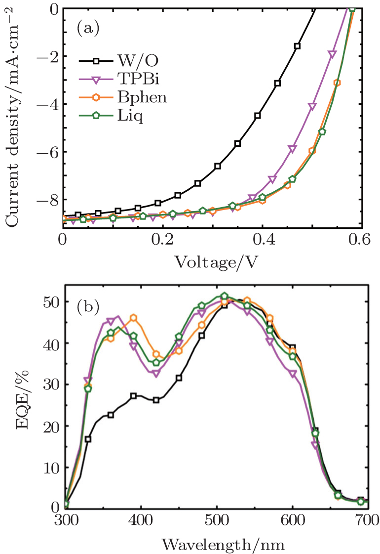 | Fig. 3. Comparison of (a) the J–V characteristics under 100 mW/cm2 illumination of AM1.5G solar spectrum, and (b) the EQE spectra of the P3HT:PCBM devices with various organic CBLs with that of the P3HT:PCBM device without a CBL. |
| Table 2. Device performance of the P3HT:PCBM devices with various organic CBLs. Every parameter in the table is the average of 16 individual devices. . |
The Liq based device demonstrates slightly higher PCE than the TPBi and Bphen based devices, which can be ascribed to the lower work function contacts provided by this organic alkali metal compound. As shown in the energy-level diagram in Fig.
It has been reported that doping can increase the carrier mobility and lead to the generation of very thin space-charge layers at the contacts beneficial for efficient injection.[42–44] The doping of organic materials by metals, such as the doping of Bphen by ytterbium (Yb), has been successfully employed both as an efficient exciton blocker layer and an optical spacer in OSC devices.[45] To further improve the device performance of the P3HT:PCBM devices based on the above described inorganic and organic CBL materials, we used the doped Bphen:Cs2CO3 and Bphen:Liq as CBLs between the active layer and the Al electrode. As mentioned above, Bphen has been proved to have a high electron mobility, so we chose it as the matrix by doping with other materials to explore more efficient doped CBL layers. To obtain the optimal device performance, we also optimized the doping ratio and the thickness of the Bphen:Cs2CO3 and Bphen:Liq layers. The Bphen matrix doped with 10% Cs2CO3 or 10% Liq with the film thickness of 4 nm was finally found as the most efficient doped CBL layer for high-performance devices.
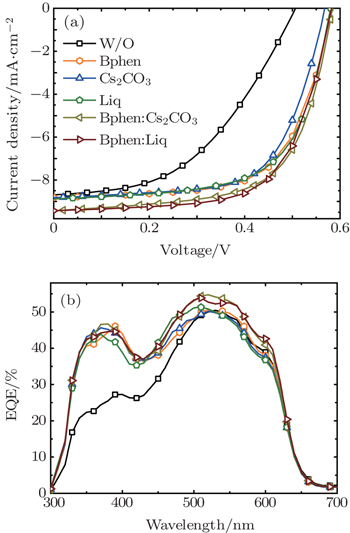
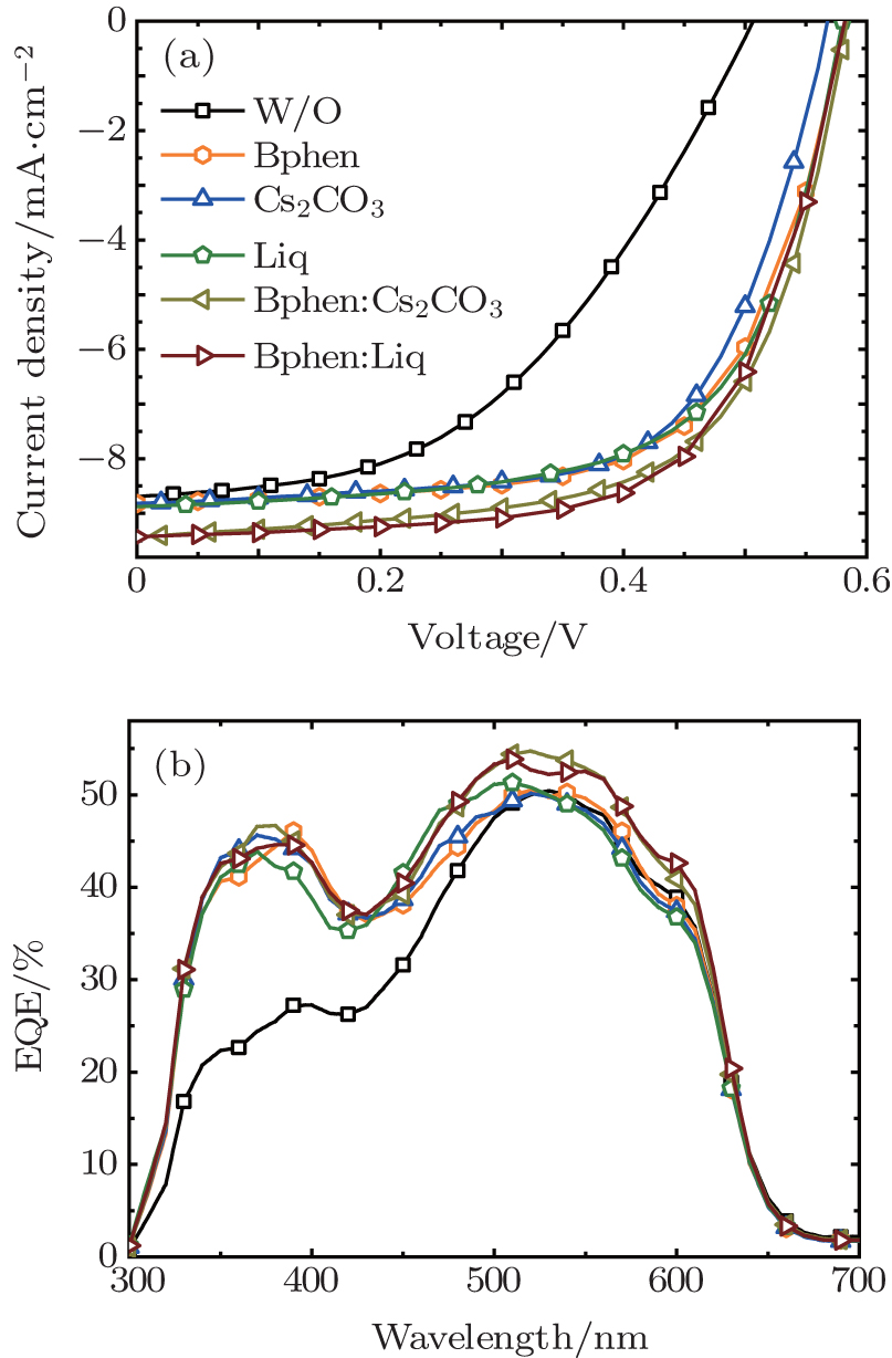 | Fig. 4. Comparison of (a) the J–V characteristics under 100 mW/cm2 illumination of AM1.5G solar spectrum, and (b) the EQE spectra of the P3HT:PCBM devices with various inorganic, organic, and doped CBLs with that of the P3HT:PCBM device without CBL. |
| Table 3. Device performance of the P3HT:PCBM devices with various inorganic, organic, and doped CBLs. Every parameter in the table is the average of 16 individual devices. . |
As depicted in Fig.
In comparison with the performance of the devices employing the neat organic or inorganic CBL (Bphen, Cs2CO3, and Liq), the doped CBL based devices demonstrate improved Jsc and comparable Voc and FF, thus increased PCE. The enhancement of Jsc can directly be reflected by the photoresponse enhancement in the EQE spectra. To elucidate the improvement of Jsc for the device with doped CBL compared with the device without CBL or with neat inorganic and organic CBL, we compared the EQE spectra of the devices with Al, Bphen/Al, Cs2CO3/Al, Liq/Al, Bphen:Cs2CO3/Al, and Bphen:Liq/Al cathodes. As shown in the EQE spectra in Fig.
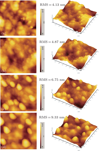
 | Fig. 5. Atomic force microscopy topographic and 3D images of P3HT:PCBM blend films on ITO/PEDOT:PSS substrate (a) without CBL, (b) with Cs2CO3 CBL, (c) with Bphen CBL, and (d) with Bphen:Cs2CO3 CBL. The scan size is 4 μm×4 μm. |
To further understand the effect of these inorganic, organic, and doped CBLs on the device performance of P3HT:PCBM cells, the surface morphologies of P3HT:PCBM photoactive layers without and with various CBLs were also investigated by using tapping-mode AFM, as shown in Fig.
We have studied the effect of a CBL between the active layer and the top metal electrode on the performance of P3HT:PCBM polymer solar cells. Several inorganic materials LiF, Cs2CO3, and ZnS, organic materials TPBi, Bphen, and Liq, as well as doped materials Bphen:Cs2CO3 and Bphen:Liq were employed as the CBL in the P3HT:PCBM polymer solar cells. Our results demonstrate that all of these inorganic and organic materials are efficient CBLs to significantly improve the device performance of the P3HT:PCBM cells. The P3HT:PCBM devices employed various CBLs possessing PCEs of 3.0%–3.3%, which are ca. 50% improved compared to that of the device without a CBL. Furthermore, by using the doped materials as the CBL, the PCE of the P3HT:PCBM device can be further improved up to 3.5%, which is ca. 70% higher than that of the device without a CBL and ca. 10% increased compared to that of the devices with neat inorganic and organic CBLs. This finding indicates that the doped Bphen:Cs2CO3 and Bphen:Liq CBLs have a great potential as efficient CBL for high-performance OSCs.
| 1 | |
| 2 | |
| 3 | |
| 4 | |
| 5 | |
| 6 | |
| 7 | |
| 8 | |
| 9 | |
| 10 | |
| 11 | |
| 12 | |
| 13 | |
| 14 | |
| 15 | |
| 16 | |
| 17 | |
| 18 | |
| 19 | |
| 20 | |
| 21 | |
| 22 | |
| 23 | |
| 24 | |
| 25 | |
| 26 | |
| 27 | |
| 28 | |
| 29 | |
| 30 | |
| 31 | |
| 32 | |
| 33 | |
| 34 | |
| 35 | |
| 36 | |
| 37 | |
| 38 | |
| 39 | |
| 40 | |
| 41 | |
| 42 | |
| 43 | |
| 44 | |
| 45 |