


Wave propagation in beams with anti-symmetric piezoelectric shunting arrays
[Chen Sheng-Bing1, †,  , Wang Gang2]
, Wang Gang2]
 |


† Corresponding author. E-mail:
Project supported by the National Natural Science Foundation of China (Grant No. 51322502).
Piezoelectric shunting arrays are employed to control the wave propagation in flexible beams. Contrary to conventional symmetric configuration, a substrate beam with anti-symmetric shunting arrays is investigated by adapted transfer matrix method. Compared with symmetric scheme, the anti-symmetric one demonstrates some distinctive characteristics. Primarily, the longitudinal and flexural waves are coupled, so they are correlated and must be considered simultaneously. Moreover, the attenuation of flexural wave is much stronger in anti-symmetric scenario, while the longitudinal wave demonstrates the converse side. As a result, the anti-symmetric scheme can be utilized to improve the vibration isolation capability of shunting arrays. Finally, the theoretical analyses are validated by finite element simulations.
Elastic wave propagation in periodic structures has been researched for several decades.[1–3] The study of wave motion in periodic structures has been exerted primarily on pass band and stop band analyses. In recent years, the propagation of elastic waves in periodic composite materials, named phononic crystal (PCs), has received much attention.[4–10] The pioneering work of Liu et al. opened new fields of PCs.[6] They examined three-dimensional PCs consisting of cubic arrays of coated lead spheres immersed in an epoxy matrix, and proposed a new kind of gap formation mechanism, i.e., locally resonant (LR) band gap. More recently, the development of LR PCs has extended to newly emerging field: acoustic metamaterials.[11–13] Acoustic metamaterials are generally regarded as materials with artificial microstructures that possess unusual physical properties such as band gaps, negative refraction, acoustic cloaking, etc.
Structures periodically shunted by electrical resonant circuits can also produce locally resonant band gaps. Moreover, the band gaps can be tuned over desired frequency ranges conveniently through adjustment of the circuit parameters. Thorp et al. utilized an array of resonantly shunted piezoelectric patches mounted on a rod to create band gaps centered at the tuning frequencies of the shunting circuits.[14] Airold et al. proposed using multi-resonant shunts to form multiple band gaps in a beam.[15] Subsequently, they proposed to design one-dimensional tunable acoustic metamaterials through periodic arrays of resonant shunts.[16] The authors also did a lot of theoretical and experimental investigations on wave propagations in structures with shunting circuits,[17–21] and tried to utilized shunting arrays to isolate vibrations propagating in flexible structures. In all these studies, symmetric scheme is generally adopted, i.e., the piezoelectric patches are oppositely mounted on the top and bottom surfaces of the substrate structure. The resulting structure is symmetric with respect to the neutral surface, in which elongation and bending deformations are decoupled, so flexural and longitudinal waves are uncoupled. Consequently, asymmetric schemes lack of elaborate exploration, and some valuable properties need to be dug out.
In this paper, we propose an anti-symmetric scheme of shunting arrays instead of the conventional symmetric layout, and obtain the dispersion relation of coupled waves in the composite beam. The propagation constants are evaluated by transfer matrix method, which is adapted for anti-symmetric scenario. Compared with the symmetric scheme, the anti-symmetric configuration demonstrates some new properties. Specifically, the attenuation of flexural dominated wave in anti-symmetric layout is much stronger than that in symmetric one. However, the attenuation of longitudinal dominated wave shows the converse feature. Finally, the theoretical predications are verified by finite element simulations.
The real structural configuration of the beam with antisymmetric piezoelectric shunting arrays is schematically shown in Fig.
 | Fig. 1. Layout of the beam assembly. (a) Front view and (b) top view. |
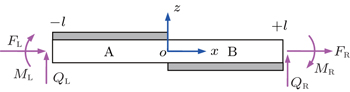
On the analogy of lattice dynamics, the wave motions in the above beam assembly can be derived from one single periodic element as shown in Fig.

 | Fig. 2. Boundary forces acting on the beam element. |
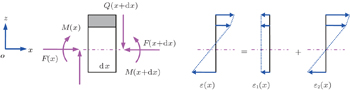
Both the beam segments A and B are asymmetrical with respect to the neutral surface of the substrate beam. As a result, the longitudinal and flexural motions in the segments are coupled. For simplicity, Euler–Bernoulli beam assumption is adopted. Consider an infinitesimally small element of segment A with length dx, as shown in Fig.
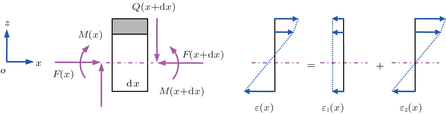 | Fig. 3. Deformation in the cross-section of segment A. |
Hence, the strain on the cross-section can be written as

Piezoelectric patches on the beam surfaces are polarized through z-axis, and assuming that all the surfaces are free of constraint except those along the x-axis. For simplicity, the directions along x, y, and z axes are represented by 1, 2, and 3 in the piezoelectric equations. Hence, the piezoelectric equations can be reduced to[14]


Solving equation set (

Each piezoelectric patch is attached to a serial RL shunting circuit as shown in Fig.


Sketch map of the shunting circuit.
Substituting Eq. (
On the other hand, the amount of electrical charge on the electrode can also be given by

Substituting Eq. (
Utilizing Eq. (

Substituting Eq. (


Combining Eqs. (


Substituting Eq. (

On the assumption of Euler–Bernoulli beam, the coupled longitudinal and flexural motions in the beam segment can be given by

If harmonic motion at frequency ω is assumed, equation (

Applying Laplace transformation into Eq. (

The solution of Eq. (
Substitution of Eq. (

On the other hand, the axial force F(x), bending moment M(x), and shear force Q(x) can be given by


By analogy, the counterpart vector

The continuity between the segment A and B in the n-th periodic element can be expressed as
Therefore,


On the other hand, utilizing Eqs. (

Substituting Eq. (

Consequently, the propagation constant μ can be obtained by solving the eigenvalue of transfer matrix
In the numerical calculation, epoxy (Young’s modulus E = 4.35 × 10⁹ Pa, Poission’s ratio v = 0.37, and density υ = 1180 kg/m3) and PZT-5H (compliance coefficient 

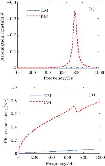
Figure
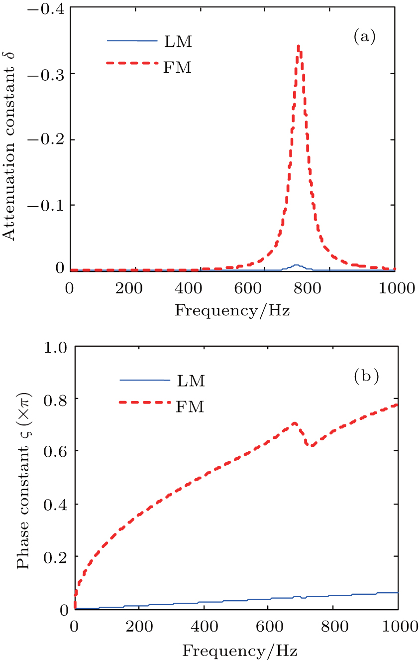 | Fig. 5. (a) Attenuation constant and (b) phase constant of the wave motions. |
As the considered wave motions are coupled, it is of interest to draw a comparison with uncoupled ones. The conventional configuration, which is generally symmetric, also bears two types of wave motions, viz. flexural wave and longitudinal wave. However, these two waves propagate independently in the beam. The comparison of attenuation constant between coupled and uncoupled wave motions are illustrated in Fig.
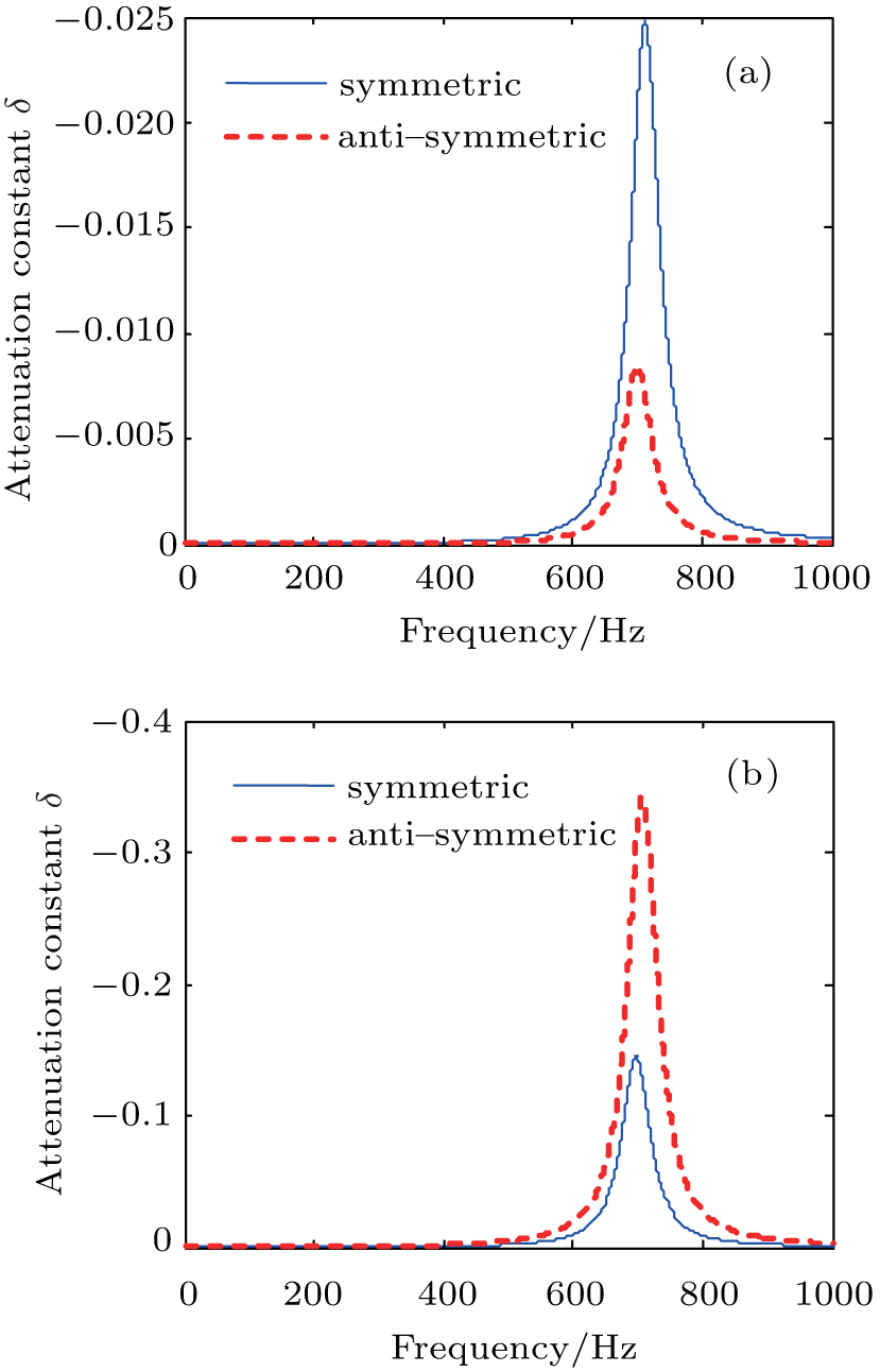 | Fig. 6. Comparison between symmetric and anti-symmetric configuration. Propagation constant of longitudinal wave (a) and flexural wave (b). |
In order to verify the above theoretical analyses, two finite element models with anti-symmetric and symmetric shunting arrays, consisting of 12 periods, are built in COMSOL, respectively. When longitudinal excitation is applied on the left end of the beam, the transmission properties of longitudinal (symmetric) and quasi-longitudinal (anti-symmetric) waves propagating in the beam are demonstrated in Fig.
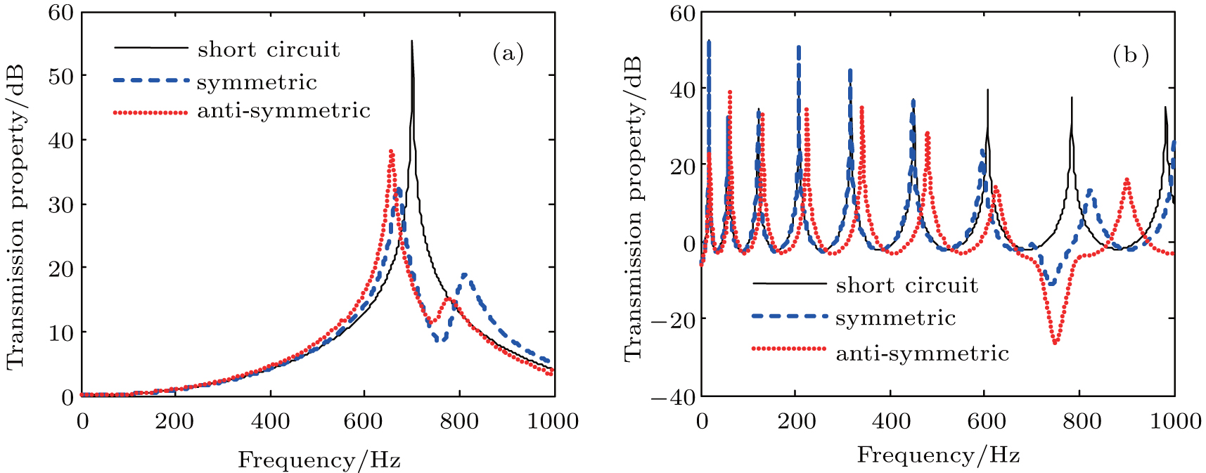 | Fig. 7. Longitudinal (a) and flexural (b) wave transmission properties of the beam. |
Wave propagation and attenuation in beams with anti-symmetric piezoelectric shunting arrays are investigated in this paper. Transfer matrix method is adapted for characterizing wave motions in the anti-symmetric model. In contrast to symmetric scenario, the longitudinal and flexural waves are coupled in anti-symmetric situation. As a result, some distinctive features are observed. First of all, the vibration energy is transformed between longitudinal and transverse degrees of freedom. Second, the attenuation of flexural wave is much stronger if the anti-symmetric configuration is adopted, which can be utilized to enhance vibration isolation capability of shunting arrays. Finally, the theoretical predications are verified by finite element simulations in COMSOL.
| 1 | |
| 2 | |
| 3 | |
| 4 | |
| 5 | |
| 6 | |
| 7 | |
| 8 | |
| 9 | |
| 10 | |
| 11 | |
| 12 | |
| 13 | |
| 14 | |
| 15 | |
| 16 | |
| 17 | |
| 18 | |
| 19 | |
| 20 | |
| 21 | |
| 22 |