Theoretical simulation of a novel birefringent photonic crystal fiber with surface plasmon resonance around 1300 nm
Li Duanming1, 2, †, , Zhou Guiyao3
Laboratory of Science and Technology on Underwater Acoustic Antagonizing, Shanghai 201108, China
Shanghai Marine Electronic Equipment Research Institute, Shanghai 201108, China
Guangdong Provincial Key Laboratory of Nanophotonic Functional Materials and Devices, South China Normal University, Guangzhou 510006, China


† Corresponding author. E-mail: duanming.li@hotmail.com

Project partly supported by the National Basic Research Development Program of China (Grant No. 2010CB327604), the National Natural Science Foundation of China (Grant No. 61377100), and the Natural Science Foundation of Guangdong Province, China (Grant No. S2013040015665).

Abstract
Abstract

In this paper, a novel birefringent photonic crystal fiber (PCF) with the silver-coated and liquid-filled air-holes along the vertical plane is designed. Simulation results show that the thickness of silver layer, the sizes of holes, and the refractive index of liquid strongly strengthen the gaps between two polarized directions. The surface plasmon resonance peak along y axis can be up to 675.8 dB/cm at 1.33 μm. The proposed PCF has important application in polarization devices, such as filters and beam splitters.

1. Introduction

Photonic crystal fibers (PCFs) have been involved in many research areas since their initial fabrication,[1,2] due to their high birefringence,[3] high nonlinearity,[4] and controllable dispersion.[5] Recently, new application of PCFs has been explored. For instance, by filling the cladding holes with gases, liquid crystals, and red blood cells, they can be applied to the chemical sensing and photochemistry,[6] polarization devices,[7] and single-cell biomechanics.[8]

In the previous reports, to achieve the polarization effects, common methods were used to change the air-hole diameters along two orthogonal directions[9,10] or using different materials.[11] Wei et al. demonstrated a birefringent PCF with a tellurite glass T2 doped ellipse core, reaching the birefringence of 7.66 × 10⁻² and nonlinearity of 3400 W−1·km−1 around 1550 nm.[12] These studies focused on obtaining the high refractive index difference between the fundamental modes at x axis and y axis.

Recently, the surface plasmon resonance (SPR) which depends on the phase matching between the incident light and SP wave, shows wide application to improve the sensitivity of optical area, such as enhancing emission of SLED to realize high power[13,14] based on the SPs’ electric field localization and enhancement characteristics. Lee et al. reported the polarization-dependent characteristics of a polarization maintaining PCF with gold wires.[15] Schmidt et al. analyzed the surface plasmon modes in the PCFs with the metal nanowire-filled PCFs, which was fabricated by the high-temperature pressure-cell.[16,17] Yu et al. simulated a selective coating of PCF with metal for SPR sensing.[18] Uebel et al. demonstrated a gold nanowire array in a PCF, where the radial electric field was resolved by a polarization sensitive near-field probe.[19] Xue et al. demonstrated a gold-coated and liquid-filled PCF, where one-side SPR was up to 508 dB/cm.[20] Liu et al. reported a PCF for two kinds of filters with the nanoscale gold film, the extinction ratio (ER) reaches to −20 dB.[21] Fan et al. numerically simulated the D-shaped PCF with gold-filled holes for the filter, gaining 292.8 dB/cm at y polarization axis.[22] Most reports mentioned above mainly concentrated on gold filling or coating, less coating processing due to more difficulty.

Compared to the gold, the cheaper silver shows some benefits, such as better thermal conductivity, easier to generate high-order mode, and relatively easy coating processing. Zhang et al. coated the silver in the air-holes and fabricated an in-fiber absorptive polarizer.[23] Bing et al. simulated and fabricated an SPR-PCF with silver-coated holes for sensor,[24] and yet, the research of silver-coating processing for PCF filter is uncommon, so we do the relative research in the hope of offering theoretical results on the silver-coated PCF for filter research and application.

In this paper, the polarization properties of a silver-coated birefringent structure PCF with water-filled holes in air holes along the y-polarized direction is studied by the finite element method (FEM). The simulation results show that the position and strength of the resonance peak are strongly influenced by the metal thickness and the cladding hole size.

2. PCF design

The cross-section of the PCF designed is shown in Fig. 1, and it consists of 6 layers of air-holes. The pitch Λ between air-holes is 2 μm. To keep different birefringence, the hole d1 = 1.8 μm is larger than the other hole d2 = 1 μm, and the outer silver-coated holes d3 = 1 μm. The d1/Λ increases the confinement ability on the energy along the x axis. In contrast, the smaller holes offer a means of leakage for the energy loss. Additionally, a liquid is filled into d3 to increase the y axis loss marked by the blue color. The black area of holes d3 is coated with Ag, the thickness is R.

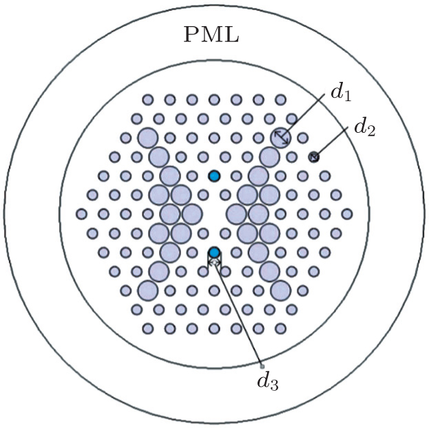
Fig. 1. Cross-section of PCF designed.

The background material is the pure silica whose material dispersion is calculated by Sellmerier formula.[25] In the finite element simulation, an anisotropic perfectly matched layer (PML) is employed. The material dispersion of silver is dependent on the Lorentz–Drude model,[26] which is defined as

where εm is the dielectric constant, ωp is the plasma frequency, k is the number of oscillators with frequency ωp, strength fj and lifetime 1/Γj, while is the plasma frequency associated with the intraband transitions with the oscillator strength f0 and damping constant Γ0.

The absorption losses of water and ethanol are very low within the considered range, so it is not necessary to consider their material dispersion in the next calculation. Their refractive indices are defined as nwater = 1.33 and nethanol = 1.36. The confinement loss is defined as

Here, λ is the wavelength of light and Im(neff) is the imaginary part of the effective refractive index neff.

Recently, the PCF fabrication processing consists of ultrasonic drilling, stacking, and so on. For coating methods, one way is suction and evaporation of the metal-nanoparticle mixtures into the fiber, and another is chemical vapour deposition (CVD). Moreover, for the silver, the chemical deposition has been usually used in the research depending on the adjusting reaction conditions for silver deposition.[23]

3. Simulation results and discussion

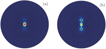
When the real part of surface plasmon polariton (SPP) modes coincides with the core guided modes neff, the energy will be transferred from the core region to the silver-coated layer, leading to a visible energy leak and sudden increase of the confinement loss. Figure 2 shows the dependence of the real part of effective index on wavelength for SPP 2nd and 3rd modes (the blue lines), the refractive index of silica glass (the pink dashed line) and the guided mode in the core (the black and purple curves represent refractive index and loss at x axis and y axis, respectively).

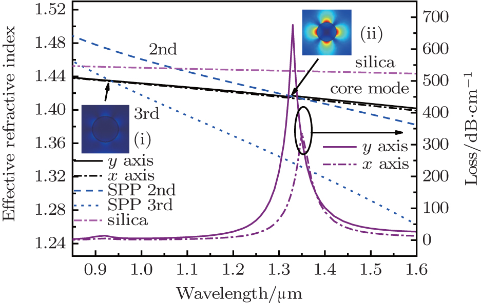
Fig. 2. Wavelength dependence of effective axial refractive index and loss for PCF (Λ = 2 μm, d1/Λ = 0.9, d2/Λ = 0.45, d3/Λ = 0.5 and the thickness of silver is 0.05 μm). The insets (i) and (ii) represent the magnitudes of electric field of the relevant modes.

As seen from Fig. 2, the phase-matching cases between the core mode and the 2nd and 3rd SPP modes occur at the specific cross point (the absorption peak around 1.33 μm for SPP 2nd and 0.92 μm for SPP 3rd), due to the SPR absorption, the guided light in the core can strongly couple to the surface of the silver layer, and significant enhancing of the confinement loss. It can be seen from the insets (i) and (ii) of Fig. 2, that the SPP 2nd intensity is much stronger than that of SPP 3rd. Furthermore, the losses of y-polarized mode are much higher than these of x polarized mode around the resonance wavelength, and the loss of y-polarized mode reaches 675.8 dB/cm at 1.33 μm, which is nearly ten times stronger than that of the x-polarized mode, and the extinction ratio[21] for the proposed fiber is approximately 10 dB at the wavelength. The FWHM (full width at half-maximum) is only 30 nm. These properties provide the PCF with a new possibility for application on the polarization devices. In addition, the x-polarized and y-polarized electric fields at 1.33 μm are shown in Figs. 3(a) and 3(b). As demonstrated in Figs. 2 and 3(b), it can be believed that the higher loss results from both the SPR and the birefringence.

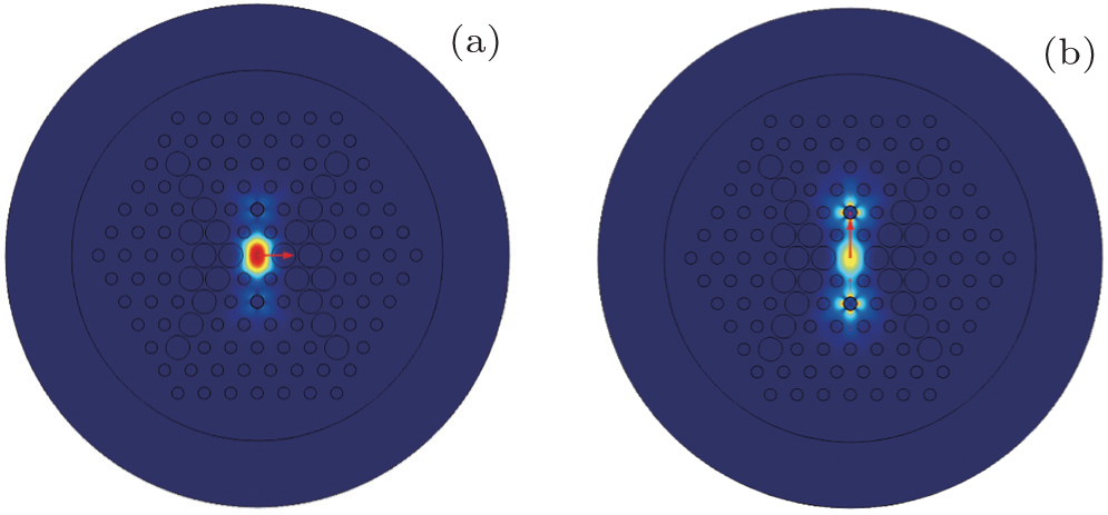
Fig. 3. Fundamental mode field along x axis (a) and y axis (b) at 1.33 μm.

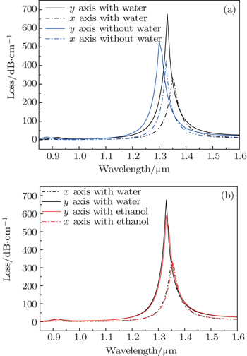
We inject the liquid into the silver-coated air-holes, and the impact of the liquid is presented in Figs. 4(a) and 4(b). The parameters are chosen as follows: Λ = 2 μm, d1/Λ = 0.9, d2/Λ = 0.45, d3/Λ = 0.5 and the thickness R = 0.05 μm. The numerical results show that the presence of liquid affects the resonance peak and wavelength. Its resonance peak is decreased and the resonance wavelength is shifted to the short wavelength without liquid along the y polarization. In contrast, the resonance peak along the x polarized direction is increased, leading to the decreasing of the difference between the two-sided polarizations. Based on the SP theory, phase matching means the effective refractive index of the core mode nneff is nearly equal to the plasmonic mode at the SPP wavelength. Hence, the core mode nneff is close to that of the core material (nsilica depends on Sellmerier formula) while the effective refractive index of the plasmonic mode is close to that of the neighboring material (liquid).[27,28] Therefore, the presence of high index liquid will enhance the coupling efficiency between the core mode nneff and the SPP mode, leading to a red shift of SPR wavelength.[29] Obviously, the presence of the liquid is of benefit for the PCF application in polarization devices. On the other hand, figure 4(b) shows the difference between the water and ethanol, when the material of liquid changes, the resonance strength and wavelength change at the same time, due to the different refractive index among liquids, which affects the effective refractive indexes in the fiber core, leading to the changing of resonance peak and wavelength. Because the presence of water has a stronger effect on the loss than that of ethanol, we will focus on the water.

Fig. 4. Impact on the presence of liquid (a) and the types of liquid (b) in the silver-coated holes.

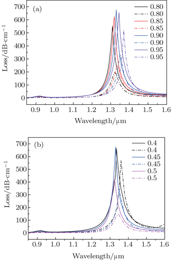
Below the birefringent structure and the thickness of the silver-coated layer will be analyzed. As introduced before, the birefringence influence could cause the expanding gap of neff between the two sides, the different SPR wavelength, and the much stronger SPR strength along y axis. Hence, the dependence of birefringence on the sizes of the diameters d1, d2, which is such that birefringence increases with the enlarging of d1 or the decrease of d2, is analyzed in Fig. 5. The loss curves of variables for d1/Λ are shown in Fig. 5(a), where Λ, d2/Λ, d3/Λ, and R are fixed at 2 μm, 0.45, 0.5, and 0.05 μm, respectively. The peak of loss increases with the increase of d1/Λ from 0.8 to 0.9 then a slight decrease at 0.95 along y axis. On the other hand, it shows continuous growth with the increase of d1 along x axis. It is worth noting that the phase-matching wavelength happens to be red shift with the increase of d1/Λ along both of the polarized directions.

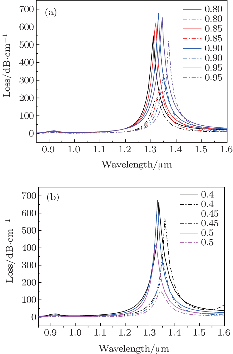
Fig. 5. Variation effects of d1/Λ (a) and d2/Λ (b) on the loss, the solid and dashed lines are the loss of core guided modes along y-polarized and x-polarized directions, respectively.

The influence of d2/Λ on the loss is presented in Fig. 5(b), where Λ, d1/Λ, d3/Λ, and R are fixed at 2 μm, 0.9, 0.5, and 0.05 μm, respectively. The resonance strength and wavelength increase slightly between 0.4 and 0.45, then decrease significantly with the increase of d2/Λ, from 0.45 to 0.5 because the enlarging of d2 blocks the light to tunnel through the outer silica cladding by the evanescent field and the SPRs between the silver-coated hole and the core region.

The birefringent structure shows a weaker impact on the position of resonance wavelength, but it strongly affects the resonance peak. The structure offers a stronger resonance peak and a suitable resonance wavelength, when parameters Λ, d1/Λ, d2/Λ, and d3/Λ are fixed at 2 μm, 0.9, 0.45, and 0.5, respectively.

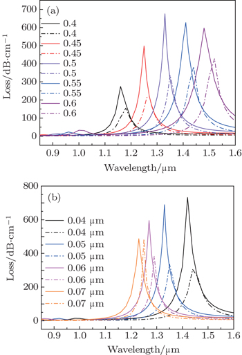
Due to the strong effect of the silver-coated hole size and silver thickness on the resonance wavelength, the outside diameter of silver-coated holes d3 is studied. As shown in Fig. 6(a), d3/Λ is increased from 0.4 to 0.6, and Λ, d1/Λ, d2/Λ, and R are fixed at 2 μm, 0.9, 0.45, and 0.05 μm, respectively. Comparing with both of the polarization directions, the gap between the polarizations shows an increasing trend of 0.4 to 0.5, and a changing trend arrives slowly and begins to decrease, when d3/Λ reaches a certain degree. It is a possible reason that the oversized interface for surface plasmon will attenuate the strength gap between the two polarizations, after the resonance peak reaches a maximum value. In addition, the increasing of d3 (silver-coated hole) also offers a resisting function for the energy leakage along y-polarization axis.

Fig. 6. Variation effects of silver-coated holes d3/Λ (a) and thickness R (b) on the loss, the solid and dashed lines are the loss of core guided modes along y polarized and x polarized directions, respectively.

As mentioned in the previous section, the coating process could possess an economical metal cost and more importantly, the resonance strength is much stronger than that filled in Ref. [20], so the dependence of the loss on R is also analyzed, as shown in Fig. 6(b), when Λ, d1/Λ, d2/Λ, and d3/Λ are 2 μm, 0.9, 0.45, and 0.5, respectively. The resonance wavelengths in both polarizations have a red shift with the decrease of the thickness. The thinner silver layer leads to the stronger evanescent wave, which means a stronger effect between the incident light and silver. Due to the energy level relaxation phenomenon, the function photons would lose part of the energy, leading to a red shift of the resonance wavelength.[19,30] Additionally, the decrease of R is followed with an increase of the difference between the two-polarization resonance peaks. When R reaches 0.05 μm, the gap between both polarizations at 1.33 μm has a better ratio with a lower FWHM. The x-polarization and y-polarization have a similar resonance peak when R = 0.07 μm. As demonstrated in Fig. 6(b), the silver layer also needs a suitable thickness, which agrees with that in Ref. [19]. Furthermore, the quality and thickness of the silver layer could be achieved by adjusting reaction conditions during the chemical deposition.[23]

4. Conclusion

In summary, a novel silver-coated and liquid-filled PCF is designed, and the resonance peak at 1.33 μm can be up to 675.8 dB/cm along the y-polarization direction. The simulation results show that the polarization properties are determined by the air-hole size and the silver layer thickness. The proposed PCF shows a significant difference of the resonance peaks between two directions within the studied wavelength range, which will have important application in polarization devices.

Reference
1Knight J CBirks T ARussell P St J 1996 Opt. Lett. 21 1547
2Knight J C 2003 Nature 424 847
3Ortigosa-Blanch AKnight J CWadsworth W JArriaga JMangan B JBirks T ARussell P St J 2000 Opt. Lett. 25 1325
4Tatsuya KYoshinori NKazuy ATaito KShubi F K 2010 Opt. Rev. 17 61
5Saitoh KFlorous NKoshiba M 2005 Opt. Express 13 8365
6Cubillas A MUnterkofler SEuser T GEtzold B J MJones A CSadler P JWasserscheid PRussell P St J 2013 Chem. Soc. Rev. 42 8575
7Ren GShum PYu XHu JWang GGong Y 2008 Opt. Commun. 281 1598
8Unterkofler SGarbos M KEuser T GRussell P St J 2013 J. Biophotonics 6 743
9Ritari TLudvigsen HWegmuller MLegré MGisin NFolkenberg J RNielsen M D 2004 Opt. Express 12 5931
10Li D MZhou G YXia C MWang CYuan J H 2014 Chin. Phys. B 23 044209
11Liu SLi S GYin G BFeng R PWang X Y2012Opt. Commun.21097
12Wei SYuan J HYu C XWu QFarrell GLi SJin BHu X M 2014 Opt. Fiber Technol. 20 320
13Zang Z GMinato TNavaretti PHinokuma YDuelk MVelez CHamamoto K 2010 IEEE Photon. Technol. Lett. 22 1041
14Zang Z GMukai KNavaretti PDuelk MVelez CHamamoto K 2012 Appl. Phys. Lett. 100 031108
15Lee H WSchmidt M ATyagi H KSempere L PRussell P St J 2008 Appl. Phys. Lett. 93 111102
16Schmidt M ARussell P St J 2008 Opt. Express 16 13617
17Schmidt M APrill S L NTyagi H KPoulton C GRussell P St J 2008 Phys. Rev. B 77 033417
18Yu XZhang YPan S SShum PYan MLeviatan YLi C M 2010 J. Opt. 12 015005
19Uebel PSchmidt M ALee H WRussell P St J 2012 Opt. Express 20 28409
20Xue J RLi S GXiao Y ZQin WXin X JZhu X P 2013 Opt. Express 21 13733
21Liu QLi S GChen H L 2015 IEEE Photon. J. 7 1
22Fan Z KLi S GChen H LLiu QZhang WAn G WLi J SBao Y J 2014 Plasmonics 10 675
23Zhang XWang RCox F MKuhlmey B TLarge M C J 2007 Opt. Express 15 16270
24Bing P BLi Z YYao J QLu YDi Z GYan X 2012 Optoelectron. Lett. 8 245
25Agrawal G P1989Nonlinear Fiber OpticsAcademic Press
26Rakic A DDjurisic A BElazar J MMajewski M L 1998 Appl. Opt. 37 5271
27Hassani ASkorobogatiy M 2006 Opt. Express 14 11616
28Gauvreau BHassani AFehri M FKabashin ASkorobogatiy M 2007 Opt. Express 15 11413
29Luan N NWang RLu YYao J Q 2014 Opt. Eng. 53 067103
30Al-Qazwini YNoor A S MArasu P TSadrolhosseini A R 2013 Curr. Appl. Phys. 13 1354