Influence of Fano interference and incoherent processes on optical bistability in a four-level quantum dot nanostructure
Department of Physics, Marvdasht Branch, Islamic Azad University, Marvdasht, Iran
† Corresponding author. E-mail: S.Hosein.Asadpour@gmail.com
1. IntroductionRecently, electromagnetically induced transparency (EIT), due to its potential applications in quantum information science and technology, has been studied by many research groups.[1–3] In this case, some related phenomena such as lasing without inversion (LWI),[4] four-wave mixing (FWM),[5–7] superluminal and subluminal light propagation,[8,9] enhanced Kerr nonlinearity,[10–12] and other[13–20] have been discussed theoretical or experimentally. Among these, optical bistability (OB) in multi-level atomic system embedded in a unidirectional ring cavity because of its wide applications in all-optical switches and logic circuits[21–25] has been the subject of many recent investigations. The researchers found that the intensity threshold of OB can be adjusted via different controllable parameters such as laser fields, phase fluctuation, quantum interference, and so on.
On the other hand, quantum coherence and interference based phenomena in semiconductor quantum wells (SQWs) or quantum dots (SQDs) have also been studied in past decade,[26–30] because of important applications in optoelectronic and solid-state quantum information science. For example, Yuan showed the slow light controlling of propagated light in vertically coupled InGaAs/GaAs quantum dots via electric fields.[26] In another study,[28] Yang et al. theoretically investigated the simultaneous formation and stable propagation of slow optical solitons pairs in SQDs with four-level biexciton-exciton cascade configuration. Moreover, the controlling of OB curves in SQWs and SQDs are also discussed by many research groups.[31–36] In fact, there are two different approaches for analyzing the optical bistability in SQWs. In the first approach,[31–36] multi-level quantum well systems can be used in a unidirectional ring cavity, and the OB can be induced via feedback mechanism of the cavity. However, in the second approach, the intrinsic OB can be obtained from the nonlinearities arising from the electron-electron interactions.[37–39]
In this paper, we use the first approach and study the optical bistability in a four-level InGaN/GaN quantum dot nanostructure confined a unidirectional ring cavity. It is demonstrated that the Fano interference for different rates of incoherent pumping rates can affect differently the properties of OB curves. Moreover, it is shown that the medium in the presence of Fano interference becomes phase-dependent, therefore the intensity threshold of OB can be easily controlled by relative phase of applied fields.
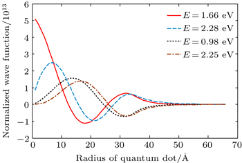
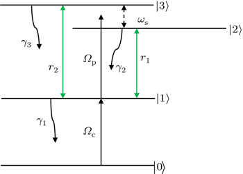
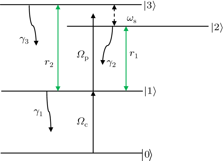
2. Model and equationsA four-level InGaN/GaN quantum dot nanostructure based on Ref. [40] is considered for studying the behaviors of optical bistability in a unidirectional ring cavity. The proportion values for calculating the wave functions and eigen-energies are as follows: the radius of quantum dot is 35 Å, the quantum dot barrier is 30 Å, the applied external voltage is 0.5 V, the length of quantum dot is 65 Å, and the number of obtained energy levels is 4. It is noted that these values result from solving the Schrödinger–Poisson equations self consistently for carrier in InGaN/GaN quantum dot’s conduction band. The normalized wave functions with related eigen-energies are shown in Fig. 1. By consideration these properties one can obtain the properties of laser fields for interacting by four-level quantum dot nanostructure. The schematic of InGaN/GaN quantum dot nanostructure is demonstrated in Fig. 2. A controlling laser field Ωc with frequency ωc is coupled with transition |0〉 → |1〉. A probe field with frequency ωp simultaneously couples level |1〉 to levels |2〉 and |3〉 with Rabi frequencies Ωp1 = μ21 Ep/2ħ and Ωp2 = μ31 Ep/2ħ, and μ21 and μ31 are the dipole moments of the respective transitions |1〉 ↔ |2〉 and |1〉 ↔ |3〉. Here, we assume μ21 = μ31 = μ, therefore Ωp1 = Ωp2 = Ωp. For the purpose of incoherent pumping, two broadband polarization fields (namely, ɛ2 and ɛ3) can be applied between energy level |1〉 and upper levels |2〉 and |3〉. The polarizations of the incoherent fields can be arranged in such a way that μ21 · ɛ3 = 0 and μ31 · ɛ2 = 0. Consequently, each of the two incoherent fields acts only on one transition so that one can avoid the interference induced by the incoherent pump fields in stimulated emissions. The corresponding total decay rates of band |i〉 (i = 0, 1,2,3) are added phenomenologically and are shown with Γi j. In the SQDs,  depicts the corresponding total decay rate of level |i〉, where γi is the population decay rate of level |i〉. Mainly, due to longitudinal-optical (LO) phonon emission events at low temperature,
  is the dephasing broadening linewidth, which may originate from electron–electron scattering and electron–phonon scattering, as well as inhomogeneous broadening due to scattering on interface roughness.[41,42] The parameter η = (γ2 γ3)1/2 represents the cross-coupling of states |2〉 and |3〉, describing the process in which a phonon is emitted by state |2〉 and recaptured by state |3〉 via LO phonon relaxation. The strength of the Fano interference, defined by p = η/(Γ21 Γ31)1/2 and the values p = 0 and p = 1, corresponds to no interference and perfect interference (no dephasing). Therefore, the strength of the Fano interference between upper states can be controlled by dephasing rates which are realized by changing the temperature appropriately.[43] In our model, the system is sensitive to the phases of the probe and coupling fields. Therefore, we should treat the Rabi frequencies as complex parameters: Ωp = |Ωp| e iφp and Ωc = |Ωc| e iφc, where φp and φc are the phases of the probe and coupling fields, respectively. The density matrix equation of motion in the rotating wave approximation and electric dipole approximation can be written as
where
ϕ =
φp −
φc. The density-matrix element
ρjk follows the symmetry relationship:

. For closeness of the system we have

. The detunings are
Δc =
ωc −
ω10 and
Δp =
ωp −
ωm. The average transition frequency
ωm is equal to

.
Now, we consider a medium with length L composed of the above described QW structure in unidirectional ring cavity.[31–37] The dynamic response of the probe field under slowly varying envelop approximation is governed by Maxwell’s equations,

P(
ωp) is induced polarization in the transitions |1〉 → |2〉 and |1〉 → |3〉, which is given by

In the steady state condition, one can obtain the field amplitude relation by substituting Eq. (
3) into Eq. (
2),

In a perfectly tuned cavity regime, the boundary conditions in the steady-state limit between the incident field

and transmitted field

are

where
L is the length of the sample,
R is the feedback mechanism, and it is responsible for the bistable behavior. Therefore, one does not expect-any bistability for
R = 0 in Eq. (
6). According to the mean-field limit
[?] and by using of the boundary conditions the steady state behavior of transmitted field is given by

where

and

are the normalized input and output field, respectively. The parameter
C =
NωpLμ2/2
ħɛ0cT is the cooperative parameter in a ring cavity. The coherence terms
ρ21 +
ρ31 in Eq. (
7) has an essential role for controlling the transmitted field in a ring cavity.
3. Results and discussionIn this section, a few numerical results for the steady state of the output field intensity versus the input field intensity in order to control the threshold of OB are discussed. In the following, it is assumed that the electron–electron effects have very small influence on our results, and also parameters to be dimensionless units by scaling γ = 1 meV and Δp = 0.
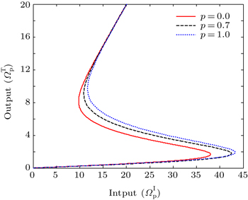
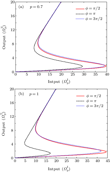
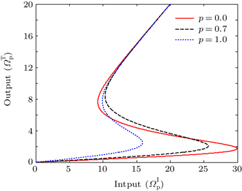
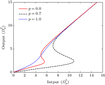
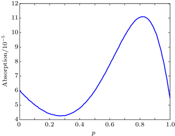
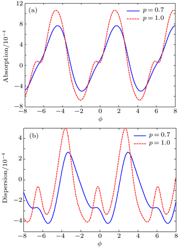
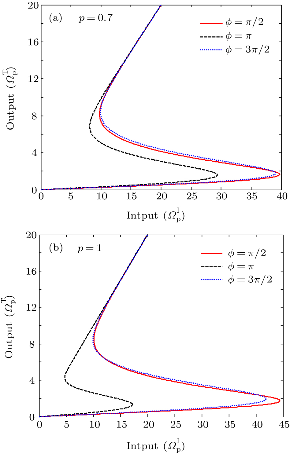
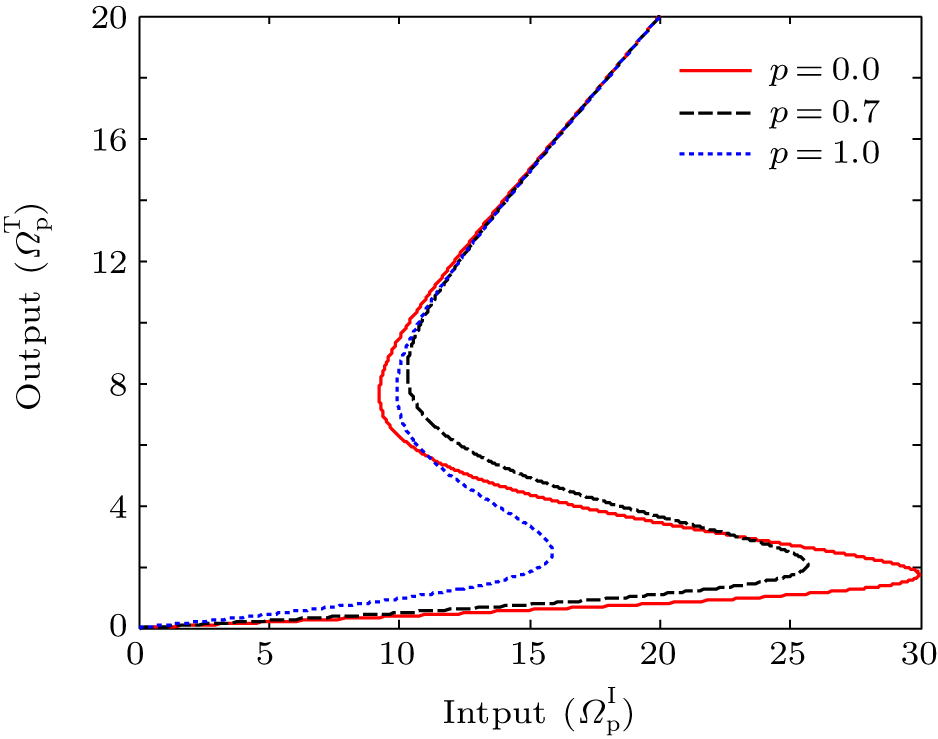
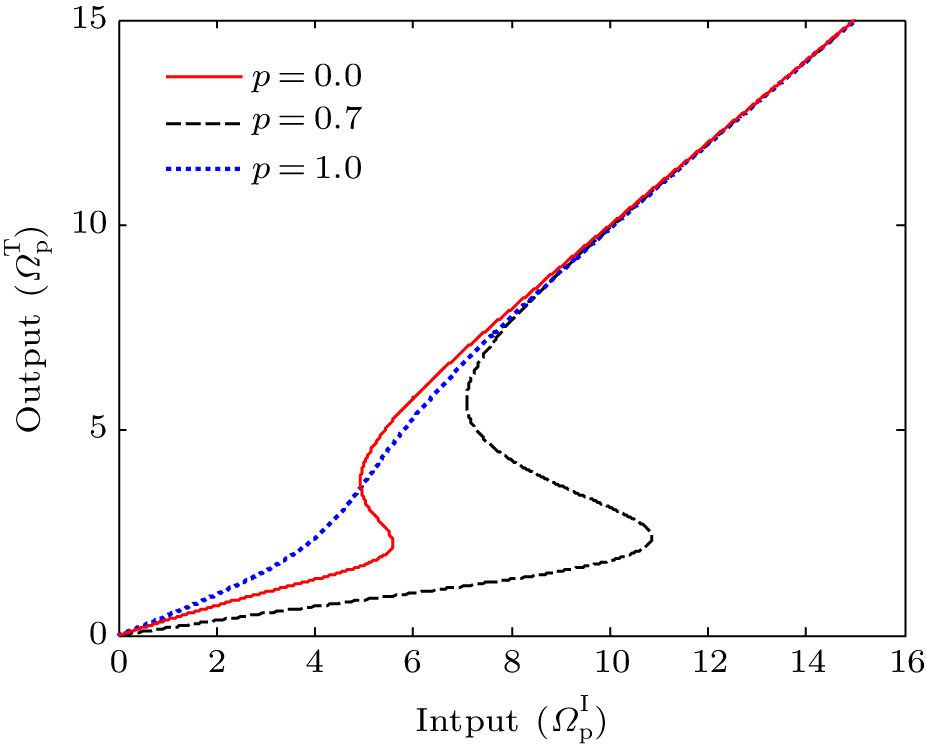
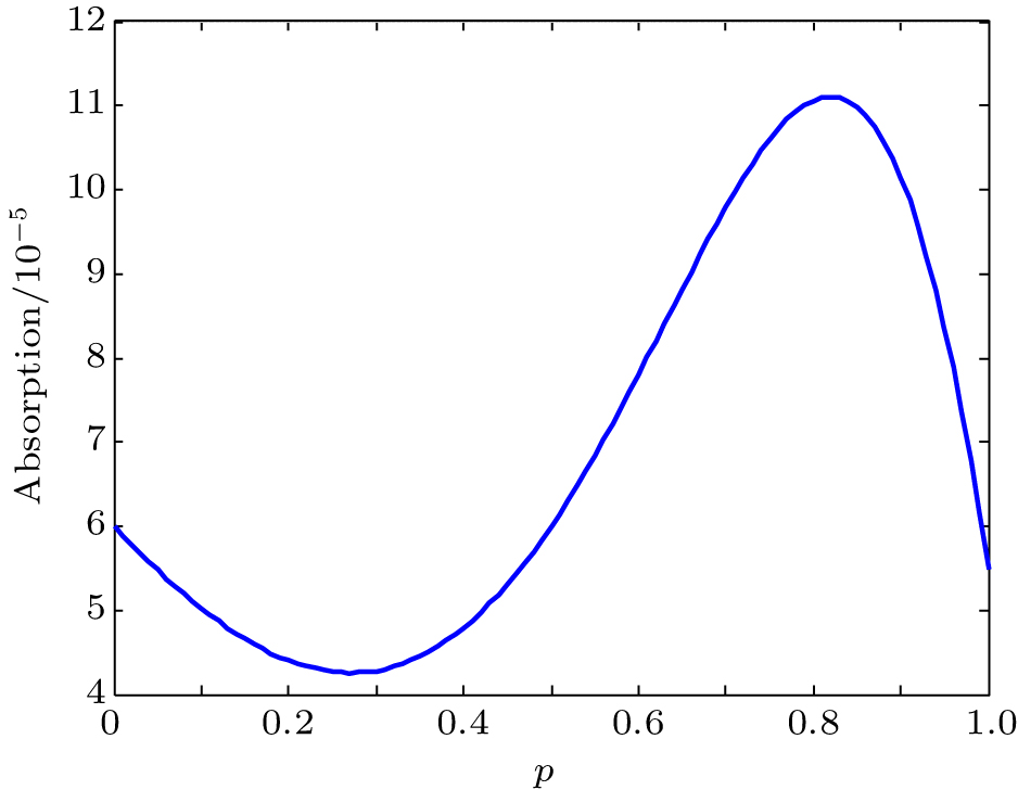
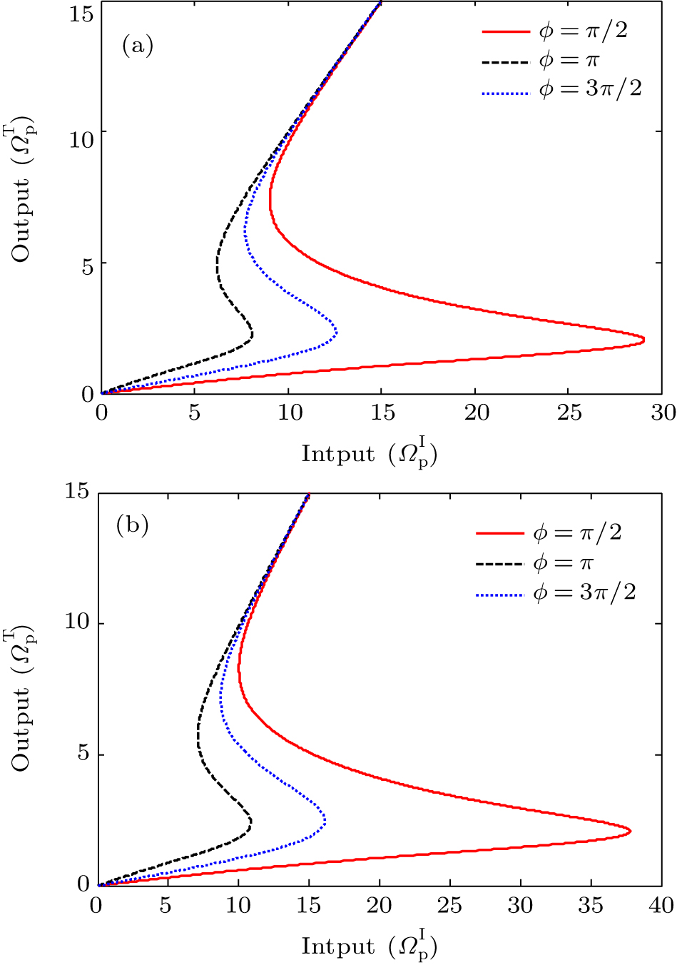
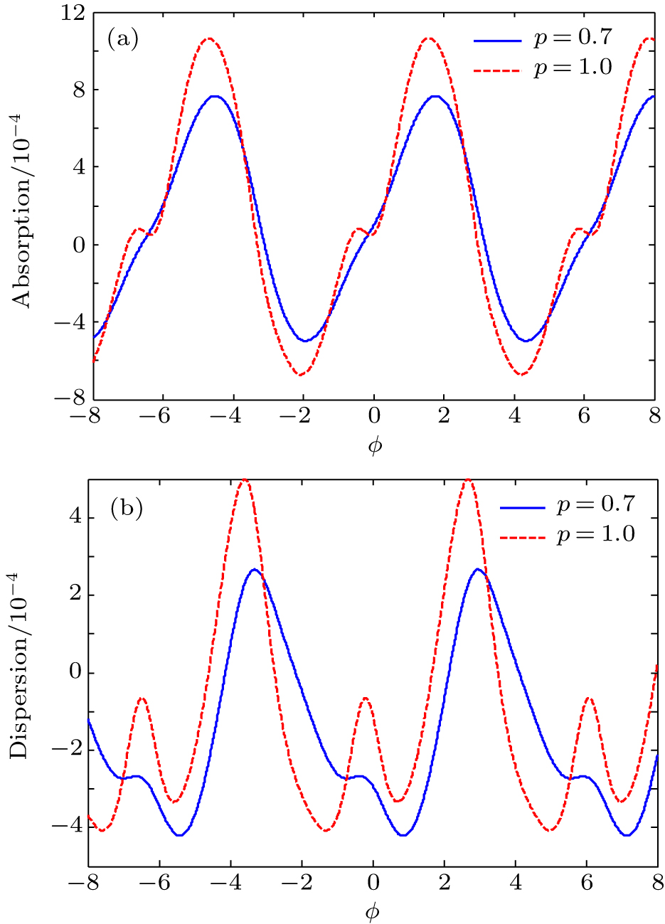
First of all, the effect of the strength or quality of the interference on OB in the absence of incoherent pumping fields can be seen in Fig. 3. We can observe the changing of threshold as we go from p = 0 (solid curve) to p = 1 (dotted curve), and the region on OB becomes narrowed. As a result, we can achieve optimally the desired bistable curve via properly tuning the Fano interference. It is known that the quantum interference due to the Fano interference makes the system completely phase-dependent. Here, we analyze the impact of the relative phase of the applied fields on the OB curves. The effect of relative phase on OB curve for Λ1 = Λ2 = 0 is displayed in Fig. 4. It can be seen that for both values of parameter p = 0.7 and p = 1, the OB thresholds dramatically changes by controlling the relative phase of applied fields. It is worth to point out that the OB thresholds for relative phase ϕ = π/2 and ϕ = 3π/2 in the case of p = 1 are greater than in the case of p = 0.7. However, for relative phase ϕ = π, the results are reverse. The behaviors of OB curve for different strengths of the Fano interference in the case of Λ1 = 2γ, Λ2 = 0 are shown in Fig. 5. It can be seen that the threshold of OB is reduced when we change the parameter p from 0 to 1. As a result, we can achieve optimally the desired bistable curve via properly tuning the Fano interference. A reasonable explanation for this is that the increase in strength of Fano interference can reduces in the absorption and enhance the nonlinearity of the electronic medium, which makes the cavity field easier to reach saturation. The effect of Fano interference on OB curve in the case of Λ1 = Λ2 = 2γ is analyzed in Fig. 6. It is found that by increasing the strength of Fano interference from 0 to 0.7, the threshold firstly increases and then by changing parameter p from 0.7 to 1, the threshold decreases to its minimal value. For further discussion of the above result, we investigate the behavior of absorption spectrum versus parameter p in Fig. 7. It can be seen that with a gradual increase of parameter p from 0 to 0.3, the absorption for the probe field decreases, and makes the cavity field easily reach saturation. By enhancing the parameter p from 0.3 to 0.8, the absorption for the probe light enhances and makes the cavity field more difficult to reach saturation, and finally by increasing parameter p from 0.8 to 1, the absorption of probe field decreases rapidly and therefore the cavity field more easier to reach saturation. In Fig. 8, the effect of relative phase between applied fields for incoherent pumping rates Λ1 = Λ2 = 2γ in two cases of p = 0.7 Fig. 8(a) and p = 1 Fig. 8(b) is discussed. By comparing with Fig. 4, we can find that the OB threshold for the case of p = 0.7 and ϕ = π has a minimum value rather than other cases. However, in Fig. 4, for the case of p = 1 and ϕ = π the OB threshold has a minimum value. Therefore, we find that the incoherent pumping fields can reduce the intensity threshold of OB by adjusting the absorption and dispersion properties of probe light. In order to have deeper attention for the above results, we plot the absorption (Fig. 9(a)) and dispersion (Fig. 9(b)) spectrums of probe light versus relative phase ϕ, in the case of Λ1 = Λ2 = 2γ. We can observe that for two cases of p = 0.7 and p = 1, the absorption and dispersion spectra have a similar behavior. However, the values of two spectra are different. For example, the value of absorption spectrum for case p = 0.7 and ϕ = π is lesser than case p = 1 and ϕ = π. This behavior makes the laser field for the case p = 0.7 and ϕ = π easier to reach saturation. These results have a good agreement with our previous results in Fig. 8.
4. ConclusionIn summary, the OB behaviors of laser probe field which circulate in a unidirectional ring cavity composed of a four-level quantum dot nanostructure have been theoretically investigated. The effect of Fano interference in the absence and presence of incoherent pumping fields have been discussed and analyzed. It has been found that the OB threshold and hysteresis curve can be manipulated by strength of Fano interference and incoherent pumping rates. Moreover, it is found that in the presence of Fano interference the medium becomes phase-dependent. Therefore, by adjusting the relative phase of applied fields the behaviors of OB can be easily controlled.


 , Solookinejad G, Panahi M, Ahmadi Sangachin E]