


High-power electro-optic switch technology based on novel transparent ceramic
[Zhang Xue-Jiao1, 2, Ye Qing1, †,  , Qu Rong-Hui1, Cai Hai-wen1]
, Qu Rong-Hui1, Cai Hai-wen1]
|
|


† Corresponding author. E-mail:
Project supported by the National Natural Science Foundation of China (Grant Nos. 61137004, 61405218, and 61535014).
A novel high-power polarization-independent electro-optic switch technology based on a reciprocal structure Sagnac interferometer and a transparent quadratic electro-optic ceramic is proposed and analyzed theoretically and experimentally. The electro-optic ceramic is used as a phase retarder for the clockwise and counter-clockwise polarized light, and their polarization directions are adjusted to their orthogonal positions by using two half-wave plates. The output light then becomes polarization-independent with respect to the polarization direction of the input light. The switch characteristics, including splitter ratios and polarization states, are theoretically analyzed and simulated in detail by the matrix multiplication method. An experimental setup is built to verify the analysis and experimental results. A new component ceramic is used and a non-polarizing cube beam splitter (NPBS) replaces the beam splitter (BS) to lower the ON/OFF voltage to 305 V and improve the extinction ratio by 2 dB. Finally, the laser-induced damage threshold for the proposed switch is measured and discussed. It is believed that potential applications of this novel polarization-independent electro-optic switch technology will be wide, especially for ultrafast high-power laser systems.
A high-power laser system with ultra-short pulse width and high average power has wide applications in modern material processing, military, space exploration, and medicine. Developing novel laser optoelectronic devices is a key for raising the current level of laser technology. An electro-optic switch using the electrically controllable refractive index modulation effect may realize a high switch speed (with response time of the order of nanoseconds or even picoseconds), which is very attractive for applications in the future all-optical network.[1] However, the fiber-type or waveguide structure limits the working area of available switch technologies, and their laser-induced damage thresholds are low, causing them unfit for use in the high-power laser systems. In order to develop high-power laser optoelectronic devices, some electro-optic crystals, such as potassium dihydrogen phosphate (KDP), lithium niobate (LiNbO3), and barium metaborate (BBO) crystals, must be used. The KDP crystal possesses a large electro-optic coefficient, a high laser-induced damage threshold, and a large size via growth from solution. However, the deliquescent properties of the crystal require very strict application environments. The LiNbO3 crystal has wide applications in optical communication and sensors because of its fast response time and low half-wave voltage; its low laser-induced damage threshold, however, restricts its usage in all-solid-state high-power laser modulation. Moreover, the polarization-dependent characteristic of the crystal is a significant destabilizing factor. The BBO crystal has an excellent damage threshold (> 20 GW/cm2) in a high power density system, however, a driven voltage of tens-of-thousands volts is harsh for a working condition.[2–5]
Transparent electro-optic ceramics, i.e., lanthanum-modified lead zirconate titanate (PLZT) and lead magnesium niobate-lead titanite (PMNT), represent a class of materials possessing relaxor properties, which easily produce birefringences and exhibit good electro-optic effects. In general, the attractive features of PLZT and PMNT include a high electro-optic coefficient (approximately 100 times of that of LiNbO3 at room temperature), a good optical transparency (larger than 95% with an antireflection film), a fast response time (about 100 ns), a large size (by the mature hot-pressing technique), and a high laser damage threshold. Especially for PMNT, a high electro-optic coefficient (2−5 times of that of the PLZT ceramic) and a low electric hysteresis (noticeably narrower in the range of 0−70°C) have also been realized.[6–12] Therefore, these quadratic electro-optic ceramics may be adapted to high-power electro-optic components, especially in ultrafast laser applications.
In this paper, a novel high-power polarization-independent electro-optic switch technology based on these kinds of transparent quadratic electro-optic ceramics is proposed and analyzed both theoretically and experimentally. The electro-optic ceramic is used as an electrically controllable phase retarder, which is inserted into a reciprocal structure Sagnac interferometer for the clockwise and counter-clockwise polarized light. By adjusting the initial polarization states of two beams, a polarization-independent electro-optic switch technology is realized. The switch characteristics, including splitter ratio and polarization state, are analyzed and simulated in detail by the matrix multiplication method. An experimental setup is also built to verify the analysis results. Experimental findings agree with theoretical results. Finally, the laser-induced damage threshold of this proposed switch is also measured and discussed. It is believed that the novel polarization-independent electro-optic switch technology will have wide potential applications in the fields of the ultrafast high-power laser systems.
The rest of this paper is organized as follows. In Section 2, the basic theory for the polarization characteristic of the proposed switch is presented by using the matrix multiplication method. In Section 3, the corresponding numerical simulation results for different splitter ratios and polarization states are presented. In Section 4, the analysis is verified through an experiment. In Section 5, some experimental measurements of the laser-induced damage threshold are discussed and the potential applications of the technology, especially in the Q-switched all-solid-state high power laser, are outlined. Finally, in Section 6, the conclusions are drawn from the present study.
The electro-optic Q-switch is a key component for generating nanosecond-to-subpicosecond laser pulses. PLZT or PMNT is a high quadratic electro-optic material and may be considered as the electrically controllable phase retarder in the Q-switch as shown in Fig.
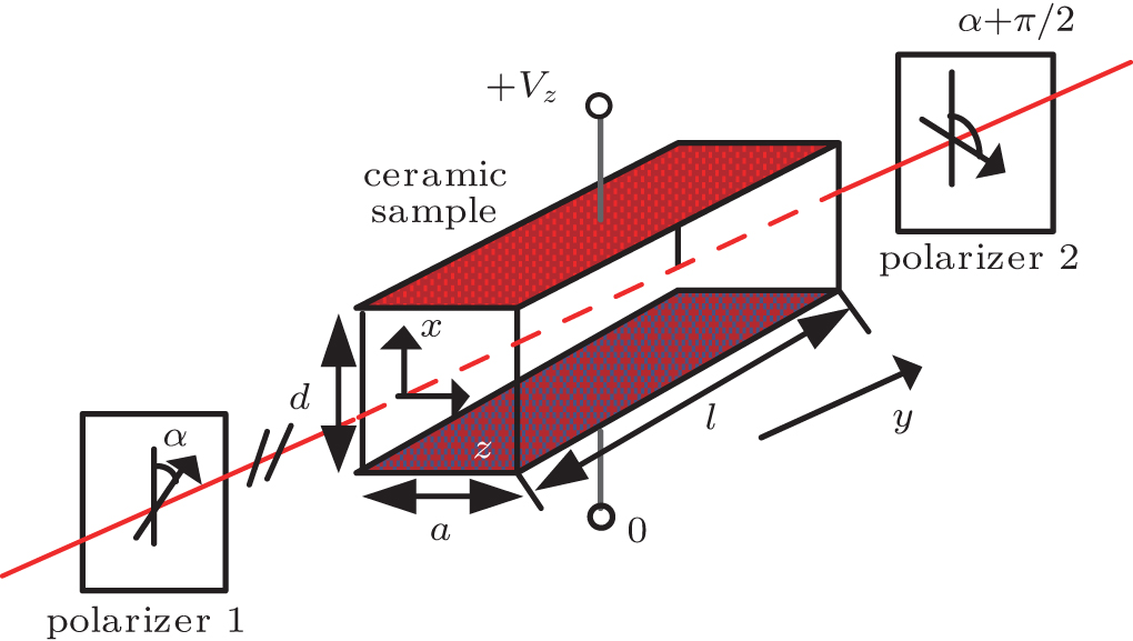 | Fig. 1. Schematic of a Q-switch design with quadratic electro-optic ceramic. |
The phase retardation contributed by the PLZT/PMNT ceramic is given by[13,14]


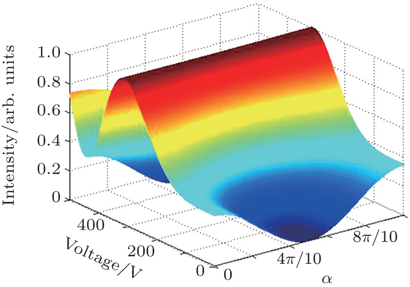
It is obvious that the switch output intensity is closely related to the input polarization state (i.e., α). This Q-switch structure is polarization-dependent. Figure
 | Fig. 2. Intensity changes with phase change and polarization angle. |
Polarization-independence is very important for a laser system and may exempt some complex optic or electric technology. In this subsection, a novel high-power polarization-independent electro-optic switch based on a reciprocal structure Sagnac interferometer and a transparent quadratic electro-optic ceramic is proposed and analyzed in detail as shown in Fig.
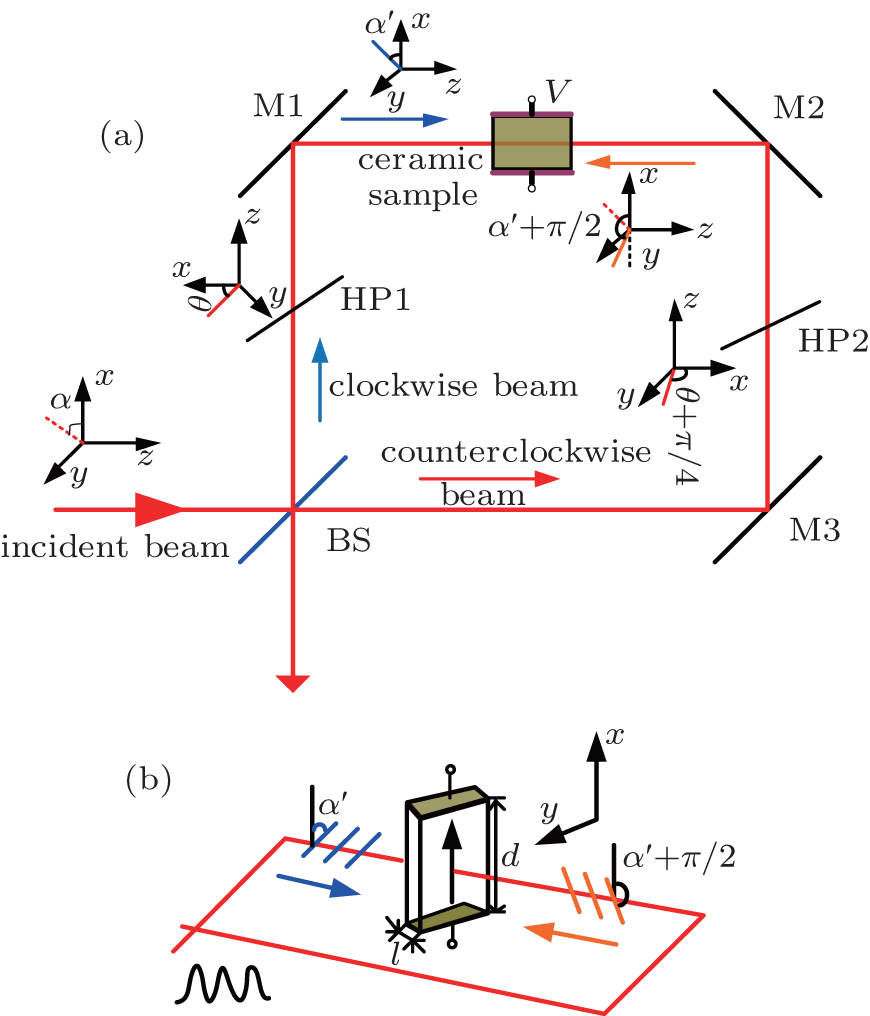 | Fig. 3. (a) Theoretical scheme of the polarization-independent switch. (b) Phase difference between two polarized beams. |
If we ignore the intensity losses due to the wave plates and beam splitter absorption, and assume that all reflections will lead to a π phase difference and the angle between the main axis of HP1 and the x axis is θ, then the Jones matrices for the components may be written as


The output is a linearly polarized beam that has a 4θ deflection angle with respect to the incident light. When the principle axis of HP1 is designed to be parallel to the applied voltage (i.e., the x axis), the output light intensity becomes independent of incident angle α and may be described as
Based on the above theoretical analysis, some numerical simulation results are given to analyze the effect of each component on the characteristic of the proposed switch. A new component of PMNT ceramic is used as an electrically controllable phase retarder and the corresponding parameters are l = 2 mm, a = 10 mm, and d = 1 mm. The effective quadratic electro-optic coefficient γeff is 28 × 10−16 m2/V2 from the measurement in Ref. [11], which describes the birefringence ability. The refractive index of the PMNT ceramic is n = 2.45. Figure
 | Fig. 4. Output intensity versus applied voltage. |
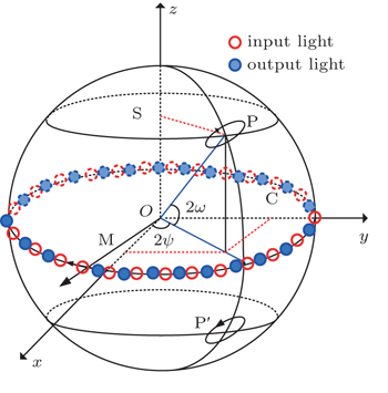
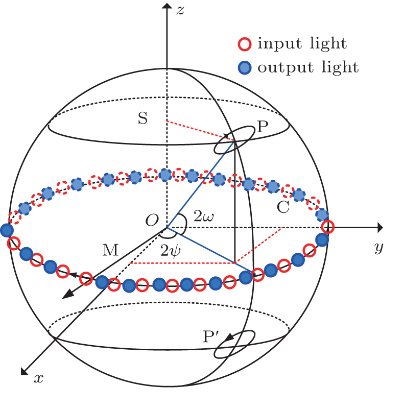 | Fig. 5. Description of polarization states on the Poincare sphere. |
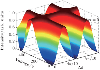
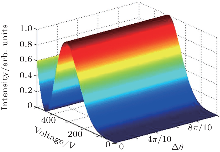
In our design, two half-wave plates are inserted into the Sagnac interferometer to maintain the polarization angle θ = π/4 strictly for clockwise light and counter-clockwise light in which they are orthogonal on the face of the electrically controllable birefringence ceramic sample. However, some angle difference Δθ = θ − π/4 will be introduced to degrade the polarization-independent performance, which is shown in Fig.
 | Fig. 6. Output intensity versus applied voltage with various angle difference Δθ. |
The effect of the incident light polarization state on the switch performance is also analyzed and simulated as shown in Fig.
 | Fig. 7. Output intensity versus applied voltage for parallel polarized intersectional light (i.e., Δθ = π/4). |
 | Fig. 8. Effect of angle Δθ =π/10 on the performance of the switch. |
The Jones matrix above shows that the output light is elliptically polarized. Thus, a Poincare sphere coordinate is used to illuminate the change in the polarization state. When Δθ = 1°, ω ranges from 0 to 8.3843 × 10⁻¹³, and ψ difference ranges from −1.5573 to 1.5573; when Δθ = π/10, the corresponding ω ranges from 0 to 1.4121 × 10⁻¹¹, and ψ changes from −1.5574 to 1.5574. The term ω is obviously so small that the approximately linear polarization vector of the output beam remains at the equator. Therefore, the angle Δθ has a slight effect on the polarization state of the output beam, but has a large effect on the extinction ratio.
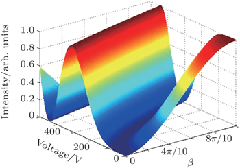
In our designed structure, various incident angles on the BS or mirror lead to different phase shifts for the reflection beam, i.e., the reflection mirror cannot exactly generate a π-phase shift. We assume that this additional phase shift is β and the corresponding Jones matrix is


Figure
 | Fig. 9. Intensity versus applied voltage with different additional phase shift β. |
The splitting ratio of the BS, which cannot be exactly 1:1 because of differences in wavelength and power, is another factor influencing the output intensity. If the splitting ratio of the BS is η : 1, the corresponding output intensity is
Figure
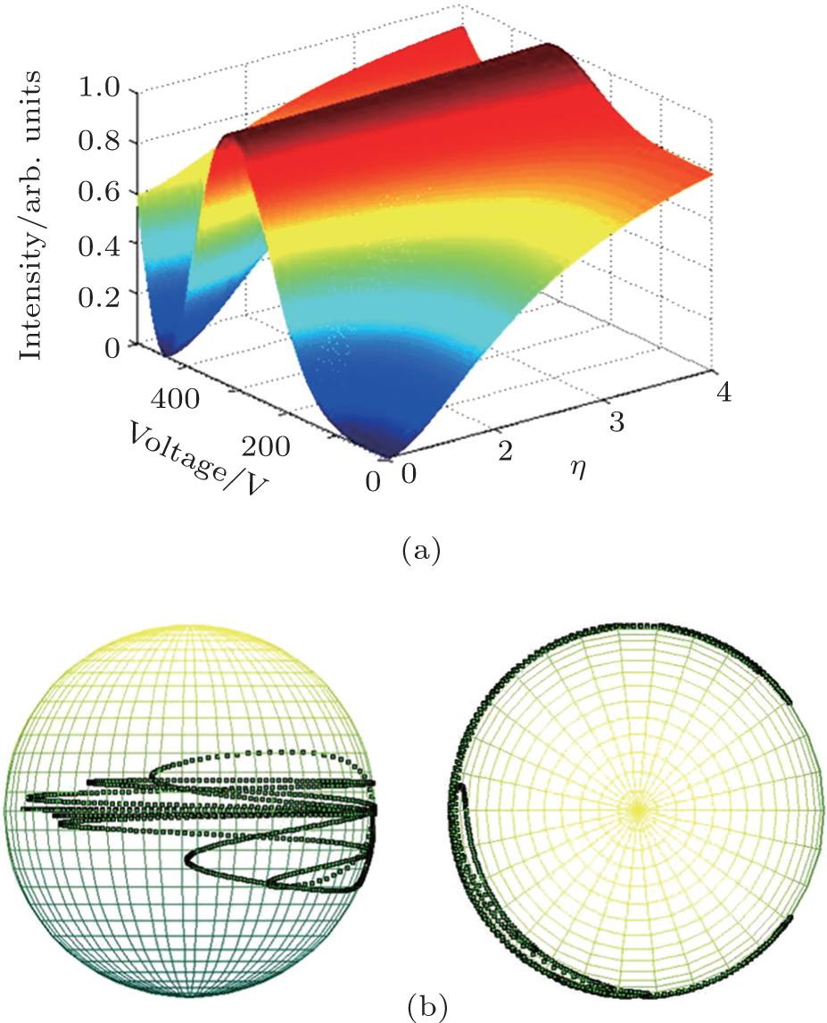 | Fig. 10. (a) Output intensity with different splitting ratios. (b) Polarization states in the Poincare sphere coordinate when η = 1.1. |
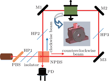
We design an experimental setup to verify the analysis described above, as shown in Fig.
 | Fig. 11. Schematic diagram of the experimental setup for the polarization-independent electro-optic switch. |
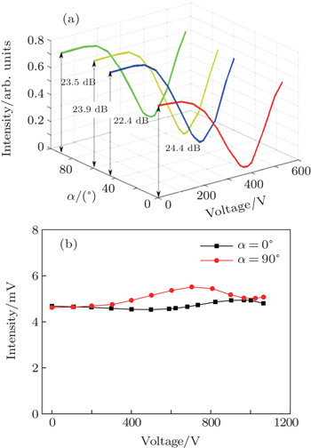
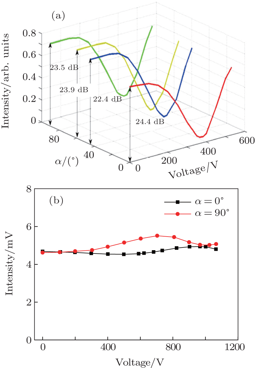 | Fig. 12. (a) Switch performance for different incident linearly polarized beams. (b) Output intensity versus applied voltage when Δθ = π/4 with different incident angles. |
Figure
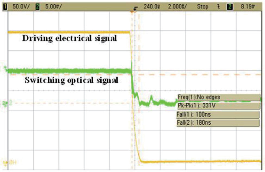 | Fig. 13. Response time of the polarization-independent modulator. |
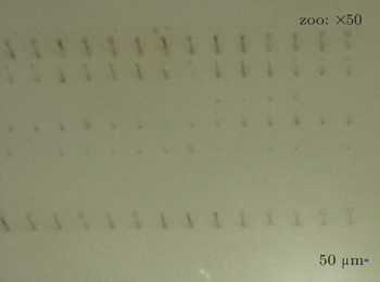
For a high-power laser system, the laser-induced damage threshold is a very important parameter that directly affects the component lifetime. Because the PBS, mirror, and HP are very mature components in laser systems, we focus on analyzing the laser damage threshold of the quadratic electro-optic ceramic in this subsection. In our experiment, the samples are polished and the surface waviness is maintained within 10 nm. Damage morphologies on the ceramic sample surface induced by nanosecond pulses at the wavelength of 1064 nm are recorded; here, the pulses are nearly Gaussian beams and the pulse duration is 12 ns. According to the one-on-one regime of ISO 11254-1,[16,17] twenty sites for each energy density are tested. Error analysis of pulse energies, spot sizes, and so on yields an error budget of damage probability of about 15%. The damage probability is observed online, and the pulse powers are adjusted to suitable levels. Damage morphologies induced by different energy levels are also observed by a microscope (VHX-700F company KEYENCE CORPORATION) with a very incident angle. Figure
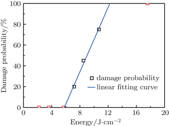
The damage probability is 100% when the irradiation energy is 17.6 J/cm2 or above. With the energy declining, the damage probability reduces to 80% when the energy is 14 J/cm2. When the energy is 5.7 J/cm2, the ceramic shows no damage spot on the surface. According to linear fitting, the laser-induced damage threshold of the ceramic is 5.79 J/cm2. By contrast, the lithium tantalite (LiTaO3) and other widely-used crystals all have a value around 1.4 J/cm2.
 | Fig. 14. Damage morphologies obtained when the samples are irradiated by nanosecond pulses of different energy levels. |
 | Fig. 15. Laser-induced damage threshold of ceramic. |
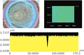
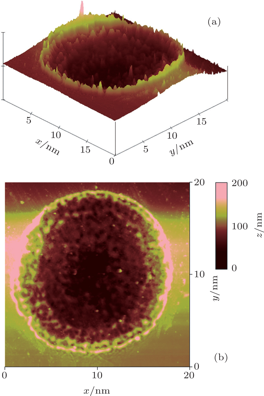 | Fig. 16. AFM images of the stereoscopic damage morphology. |
Figure
Variations of damage spot diameter with irradiation energy are analyzed. Variations of damage depth with damage spot diameter and the damage morphology in the ceramic are also detected and recorded. Small damage spots are observed by atomic force microscopy, and the images obtained are presented in Fig.
 | Fig. 17. Damage and defect morphology. |
A damage dot caused by defects in the ceramic is presented in Fig.
The grain boundary and porosity in polycrystalline ceramic are known to influence transmittance. Lengthening the holding time and two-stage sintering the conventional starting materials lead to the decrease of the ultimate residual porosity, improve the density and transmittance, and yield a pure phase perovskite structure. Over 10% La doping can yield the pyrochlore phase and affect the transmissivity of the material. Thus, La doping must be controlled to an appropriate proportion. The electric domain size is another key factor affecting the transmittance and electro-optic performance: this factor also depends on the Pt and La contents. During cooling, the furnace is partially opened to achieve different cooling speeds and obtain smaller grains. All these steps will be taken into consideration in future studies to raise the laser-induced damage threshold.
The polarization-independent switch can be considered as a Q-switch optical intensity modulator for intracavity or external cavity laser modulation[18] as shown in Fig.
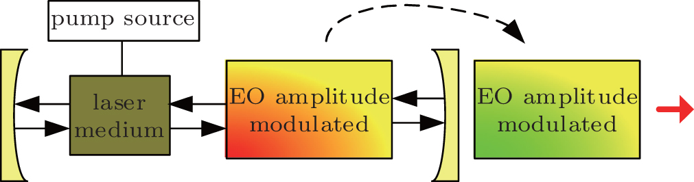 | Fig. 18. Intracavity and extracavity beam control in high power ultra-short pulse laser application. |
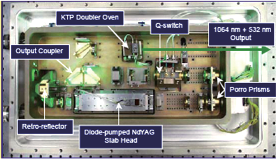 | Fig. 19. CALIPSO laser transmitter. |
A novel high-power polarization-independent electro-optic switch technology based on a reciprocal structure Sagnac interferometer and a transparent quadratic electro-optic ceramic is investigated. The polarization-independent characteristic of the device and the output optical beam induced by the controllable electric field are analyzed theoretically, simulated numerically, and implemented experimentally. Research shows that the experimental results in the free space Sagnac structure are accordant very well with the theoretical analysis. Some potential applications of the high-power laser system for polarization-independent modulation are discussed. The laser-induced damage threshold of the ceramic is also measured in this study. Damage morphologies obtained under different powers and different pulse widths are shown and some techniques, such as two-step sintering and lengthening holding time, are speculated to increase the laser-induced damage threshold.
| 1 | |
| 2 | |
| 3 | |
| 4 | |
| 5 | |
| 6 | |
| 7 | |
| 8 | |
| 9 | |
| 10 | |
| 11 | |
| 12 | |
| 13 | |
| 14 | |
| 15 | |
| 16 | |
| 17 | |
| 18 | |
| 19 |