STED microscopy based on axially symmetric polarized vortex beams
Zhou Zhehai†, , Zhu Lianqing‡,
Beijing Key Laboratory for Optoelectronic Measurement Technology, Beijing Information Science and Technology University, Beijing 100192, China


† Corresponding author. E-mail: zhouzhehai@bistu.edu.cn

‡ Corresponding author. E-mail: zhulianqing@sina.com

Project supported by the National Natural Science Foundation of China (Grant Nos. 61108047 and 61475021), the Natural Science Foundation of Beijing, China (Grant No. 4152015), the Program for New Century Excellent Talents in Universities of China (Grant No. NCET-13-0667), and the Top Young Talents Support Program of Beijing, China (Grant No. CIT&TCD201404113).

Abstract
Abstract

A stimulated emission depletion (STED) microscopy scheme using axially symmetric polarized vortex beams is proposed based on unique focusing properties of such kinds of beams. The concept of axially symmetric polarized vortex beams is first introduced, and the basic principle about the scheme is described. Simulation results for several typical beams are then shown, including radially polarized vortex beams, azimuthally polarized vortex beams, and high-order axially symmetric polarized vortex beams. The results indicate that sharper doughnut spots and thus higher resolutions can be achieved, showing more flexibility than previous schemes based on flexible modulation of both phase and polarization for incident beams.

1. Introduction

In recent years, stimulated emission depletion (STED) microscopy has attracted much attention because of its unique microscopic properties, such as higher imaging speed and super-resolution imaging capacity, and wide applications in many fields.[1] The technique was invented by Hell and Wichmann,[2] and further realized experimentally by Hell and Thomas.[3] STED achieves the super-resolution imaging by use of the non-linear response of fluorophores, and differs from PALM[4] and STORM[5] which use mathematical models to reconstruct a sub-diffraction limit using a set of diffraction limited images.

STED works by depleting fluorescence in specific regions of the sample, while leaving a center focal spot active to emit fluorescence. This focal area can be engineered by altering the properties of the pupil plane of the objective lens or modulating the phase and polarization properties of incident beams. The most common means is to use diffractive optical elements (DOEs) by phase modulation for incident beams to get a doughnut shape,[6] and an axial resolution on the order of 100 nm has been demonstrated using different DOEs. Another popular way by phase modulation is to use an optical vortex, and a twisted light beam with an orbital angular momentum causes a zero point at the center, which can be easily operated with a spiral phase plate (SPP)[7] or a spatial light modulator (SLM).[8] In addition, several methods based on polarization modulation for incident beams have been proposed, and higher resolution has been achieved. The use of Gauss–Laguerre vector beams in STED microscopy was studied first,[9] and effects of coherence and vector properties of the light on the resolution limit in the STED microscopy were then discussed.[10] Meanwhile, several methods using cylindrical vector beams (CVBs) in STED microscopy were demonstrated,[1113] including radially polarized beams and azimuthally polarized beams. All these results have verified the excellent applicability of vector beams in the STED microscopy.

In the paper, we propose a new means using axially symmetric polarized vortex beams (ASPVBs) in STED microscopy, which have vector-vortex polarization and helical phase distributions, and thus have some unique tight focusing properties. The concept of ASPVBs is introduced first, and the operation principle and simulation results are presented. The results show a doughnut spot can be achieved by flexibly modulating both phase and polarization of depletion laser beams, and also more flexibility and potential of higher resolution than previous schemes.

2. Basic method

ASPVBs are vector beams with axially symmetric polarization and vortex phase distributions,[14] whose electric field in a cylindrical coordinate can be expressed as

where A is a constant, l0 (θ) is the pupil apodization function which denotes the relative amplitude and phase of the incident beam, l is the topological charge, P is the polarization order, and er, eϕ are unit vectors in radial and azimuthal directions, respectively. If P is 1, they are well-known cylindrical polarized vortex beams, including radially polarized vortex beams (P = 1, ϕ0 = 0) and azimuthally polarized vortex beams (P = 1, ϕ0 = π/2). The focused field of ASPVBs can be obtained using vector diffraction theory,[15]

where S(rs,ϕs,zs) is an observation point near focus, and Er, Eϕ, and Ez are the amplitudes of the radial, azimuthal, and longitudinal components, respectively, and the total field is the sum of the three components. k is the wavelength number, and θ denotes the focusing angle (the angle between the optical axis and the propagation vector). Hence, the relationship between the maximum of θ and the NA of the objective lens is given by α = sin−1(NA/n), where n is the refractive index of the surrounding medium.

Furthermore, the three orthogonal components of the focusing field can be simplified, respectively, as

where X = −krs sinθ. Based on Eqs. 3(a)3(c), we can individually calculate the intensity distributions corresponding to the three orthogonal components as well as the total field near focus. By analyzing the Bessel functions JlP, JlP+1, and JlP+2 in Eqs. 3(a)3(c), we find that the transverse components of focused fields are not zero on the optical axis on condition that P = l and P = l + 2, and the longitudinal component also gives rise to a nonzero optical intensity on the optical axis under the condition of P = l + 1. So the total focused field shows nonzero optical intensity when P = l, P = l + 1, or P = l + 2. The reported results have shown that the focused ASPVBs can present many types of focal patterns based on different combinations of polarization orders and topological charges, and some tight focused doughnut and spot fields can be obtained,[9] which can be used in optical trapping, material processing, and microscopy.

Figure 1 schematically shows our proposed STED scheme. Two lasers with two different wavelengths are used in the system, where laser 1 with shorter wavelength is used as the simulated beam, and the laser 2 with larger wavelength is used as the depletion beam. Then both laser beams are processed similarly by pin-hole filters (PHF1 and PHF2) and collimators (L3 and L4), and the collimated beams are converted into the ASPVBs using the polarization converters (PV1 and PV2), where the polarization converters are optical beam transformation systems based on liquid crystal modulators (SLMs).[14] Subsequently, the converted beams can be modulated in phase and amplitude by pupil filters (PF1 and PF2), and the modulated beams are focused into the sample by the objective lens (L5) after reflection by two dichroic splitters (DS1 and DS2), where the sample is placed onto a 3D stage, and the 3D scanning of the sample is realized by moving of 3D stage. The activated fluorescence signals are collected by another objective lens (L6) and detected by a detector after a beam filter and a pinhole. The role of the filter is to block the reflected stimulated and depletion beams and only to pass through the fluorescence signals, and the role of the pinhole is to further enhance the imaging resolution based on the confocal imaging principle.

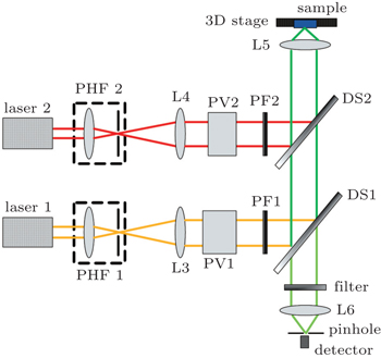
Fig. 1. Schematic diagram of the STED microscopy using ASPVBs. PHF: pin-hole filter, L: lens, PV: polarization converter, PF: pupil filter, DS: dichroic splitter.

For STED, a modified Abbe’s equation describes its sub-diffraction resolution as

where n is the refractive index of the medium, I is the intracavity intensity, and Isat is the saturation intensity. Theoretically, the resolution approaches zero if the intracavity intensity I is infinite. In fact, the intensity is not infinite to avoid damage to sample, and the resolution is also influenced by other factors, such as delay time, spot size, pulse lifetime, and so on.

3. Simulation results

First, we consider the use of cylindrically polarized vortex beams in our proposed STED scheme. Here we separately present the results using radially polarized beams (RPBs) and azimuthally polarized beams (APBs), as shown in Figs. 2 and 3, where the numerical aperture (NA) of objective lens is 0.95, all length measurements are in units of wavelength, and

Obviously, excitation spot and doughnut-shape de-excitation spot can be obtained by modulation of topological charges of cylindrically polarized vortex beams, and super-resolution imaging can be achieved. As we know that, a sharper spot can be realized for tight focusing of RPBs which have been used in microscopy. For radially polarized vortex beams (RPVBs), a doughnut-shape spot is presented if the topological charge is larger than 1, which can be used as the de-excitation beam. As shown in Fig. 2, the full width at half maximum (FWHM) of spot is 0.68λ for the focused RPBs, and the FWHM for the central dark hole is 0.70λ for the focused RPVBs when the NA of objective lens is 0.95. Oppositely, APBs can be used as de-excitation beams for their hollow focusing, and azimuthally polarized vortex beams (APVBs) with topological charge 1 can be used as excitation beams. As shown in Fig. 3, the FWHM of the spot is 0.48λ for the focused APVBs, and the FWHM of the central dark spot is 0.46λ for the focused APBs. In fact, the spot or hole size can be reduced if an objective lens with larger NA is used. Meanwhile, we can also choose the combination of RPBs and APBs as excitation and de-excitation beams.

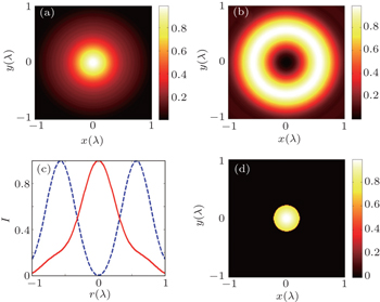
Fig. 2. Calculated results for STED microscopy using RPBs and RPVBs, where (a) excitation spot is formed by focusing RPBs, (b) doughnut-shape de-excitation spot is formed by focusing RPVBs (l = 2). (c) The line scan of intensity distributions for panels (a) and (b). (d) Remaining focal area allowing fluorescence.
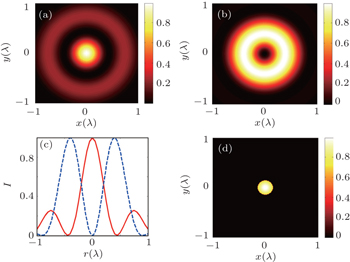
Fig. 3. Calculated results for STED microscopy using APBs and APVBs, where (a) excitation spot is formed by focusing APVBs (l = 1), (b) doughnut-shape de-excitation spot is formed by focusing APBs. (c) The line scan of intensity distributions for panels (a) and (b). (d) Remaining focal area allowing fluorescence.

Figure 4 further shows the results using high-order axially symmetric polarized vortex beams, where the polarization order is 5, all length measurements are in units of wavelength,

and the NA of objective lens is 0.95. The focusing field of the beam with topological charge 3 presents a tight spot with FWHM 0.46λ, but a doughnut-shape spot is shown for focusing field of the beam with l = 2, whose FWHM is 0.34λ. Both beams can be used in STED microscopy as excitation and de-excitation beams, and the remain focal region is shown in Fig. 4(d). In fact, ASPVBs with different polarization orders and topological charges can be chosen as excitation and de-excitation beams.[15] It is worth noting that the remaining focal area is not strictly circular, but a little polygonal, which originates from the polygonal shape of excitation spots. However, it will not affect substantially the imaging quality because of its very little shape difference from an ideal circle.

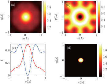
Fig. 4. Calculated results for STED microscopy using high-order ASPVBs (P = 5), where (a) excitation spot is formed by focusing ASPVBs (l = 3), (b) doughnut-shape de-excitation spot is formed by focusing ASPVBs (l = 2). (c) The line scan of intensity distributions for panels (a) and (b). (d) Remaining focal area allowing fluorescence.

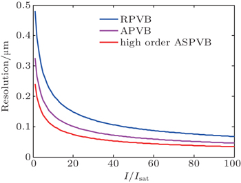
Finally, the sub-diffraction resolutions for these three kinds of ASPVBs are calculated as shown in Fig. 5, where the NA of objective lens is 0.95. It is shown that the sub-diffraction resolution increases with the increase of the ratio of the intracavity intensity to the saturation intensity, but in practice it is difficult to get a high ratio because of the limitation of the intracavity intensity. In addition, we can find that the case using high-order ASPVBs have presented smaller resolution compared to other two cases using RPVBs and APVBs. It is safe to say that the unique focusing properties of high-order ASPVBs originate from the spatial interference of the incident beam, which is naturally influenced by the polarization state and phase distribution of the incident beam. The high-order ASPVBs have more complex polarization and phase distributions than RPVBs and APVBs, so it is possible that some smaller focused spots can be obtained by appropriately choosing polarization orders and topological charges of the ASPVBs, just as shown here.

Fig. 5. The sub-diffraction resolutions using three different ASPVBs when the ratio of the intracavity intensity to the saturation intensity changes from 1 to 100, where NA = 0.95.
4. Conclusions

A STED microscopy scheme using ASPVBs has been proposed, and some simulation results for radially polarized vortex beams, azimuthally polarized vortex beams, and high-order ASPVBs are demonstrated, and excitation and de-excitation fields are calculated. The results verify the feasibility of the STED scheme using ASPVBs, which provide more flexibility and higher resolution by flexibly modulating the phase and polarization of incident beams.

Reference
1Müller TSchumann CKraegeloh A 2012 Chem. Phys. Chem. 13 1986
2Hell S WWichmann J 1994 Opt. Lett. 19 780
3Klar T AHell S W 1999 Opt. Lett. 24 954
4Betzig EPatterson G HSougrat RLindwasser O WOlenych SBonifacino J SDavidson M WLippincott-Schwartz JHess H F2003Science3131642
5Rust M JBates MZhuang X W 2006 Nat. Methods 3 793
6Wildanger DPatton B RSchill HMarseglia LHadden J PKnauer SSchönle ARarity J GO’Brien J OHell S WSmith J M 2012 Adv. Mater. 24 OP309
7Beijersbergen M WCoerwinkel R P CKristensen M 1994 Opt. Commun. 112 321
8Heckenberg N RMcDuff RSmith C P 1992 Opt. Lett. 17 221
9Török PMunro P R T 2004 Opt. Express 12 3605
10Gao W R 2008 J. Opt. Soc. AM. A 25 1378
11Hao X AKuang C FWang T TLiu X 2010 J. Opt. 12 115707
12Xue YKuang C FLi SGu ZLiu X 2012 Opt. Express 20 17653
13Liu YKuang C FLiu X 2015 J. Opt. 17 045609
14Chen HHao J JZhang BXu JDing J PWang H T 2011 Opt. Lett. 36 3179
15Zhou Z HGuo Y KZhu L Q 2014 Chin. Phys. B 23 044201