Improving the performance of perovskite solar cells with glycerol-doped PEDOT:PSS buffer layer
Key Laboratory of Optoelectronic Technology and Intelligent Control of Ministry Education, Lanzhou Jiaotong University, Lanzhou 730070, China
† Corresponding author. E-mail: ljfpyc@163.com
‡ Corresponding author. E-mail: yjxia73@126.com
Project supported by the National Natural Science Foundation of China (Grant Nos. 61264002, 61166002, 91333206, and 51463011), the Natural Science Foundation of Gansu Province, China (Grant No. 1308RJZA159), the New Century Excellent Talents in University of Ministry of Education of China (Grant No. NCET-13-0840), the Research Project of Graduate Teacher of Gansu Province, China (Grant No. 2014A-0042), and the Postdoctoral Science Foundation from Lanzhou Jiaotong University, China.
1. IntroductionPerovskite solar cells based on organometal halide light absorbers have been considered as a promising photovoltaic technology due to their direct bandgap, high absorption coefficient, long exciton diffusion length, and excellent charge transport properties that lead to their superb power conversion efficiency (PCE).[1–6] Typical perovskite solar cells have employed an electron-transport layer (ETL)/perovskite material/hole-transport layer (HTL) structure. Initial meso-superstructured-type solar cells based on a mesoporous TiO2 layer as the electron-transport layer require high-temperature processing (> 450 °C), which hinders the commercialization.[7–9] Therefore, many approaches have been developed to avoid the high-temperature barrier. One promising approach, a planar heterojunction device architecture, is particularly interesting, owing to its simple cell configuration and possible low-temperature fabrication.[10–12] Sun et al.[10] first reported the planar heterojunction perovskite solar cells, in which PEDOT:PSS was used as the hole transporter and fullerene derivatives as the electron transporter. However, the electrical conductivity of PEDOT:PSS thin film is generally low, the introduction of a PEDOT:PSS buffer layer in the solar cell inevitably increases the series resistance of the whole device, affecting the short circuit current density (JSC) and the fill factor (FF). Many promising techniques have been developed to mainly improve the electrical property of PEDOT:PSS, mostly by exposing PEDOT:PSS to selective reagents in polymer solar cells. For example, the addition of various organic solvents, surfactants, salts, and acids such as H2SO4,[13] dimethyl sulfoxide (DMSO),[14] methanol,[15] Zonyl FS-300,[16] N,N-dimethyl for mamide (DMF),[17] tetrahydrofuran (THF), acetonitrile (ACN), isopropyl alcohol (IPA)[18] and sorbitol[19] led to significantly enhanced electrical properties of PEDOT:PSS films. Meanwhile, it was reported that many properties of PEDOT:PSS such as transmittance, morphology, and work function would be changed when the low conductivity PEDOT:PSS was doped with different polar solvents or organic compounds in polymer solar cells. To the best of our knowledge, there is little in the literature reporting on the effect of the addition of some solvent additives to the PEDOT:PSS on the performance of perovskite solar cells.
Therefore, we analyze the changes of transparency, electrical conductivity and surface morphology of PEDOT:PSS thin film doped with glycerol of different concentrations, as well as the influence of doped PEDOT:PSS thin film on the performance of a perovskite solar cell. The results indicate that the perovskite solar cell with ITO/PEDOT:PSS/CH3NH3PbI3/PC61BM/Al configuration, which is prepared by doping 6% glycerol into the PEDOT:PSS, achieves an open-circuit voltage (VOC) of 0.85 V, a JSC of 17.92 mA·cm−2, fill factor (FF) of 72.39%, and power conversion efficiency (PCE) of 11.03%, where the cell’s efficiency increases 28.70% compared with un-doped ones. Hence, doping glycerol into PEDOT:PSS is an important method to improve the efficiency of a perovskite solar cell.
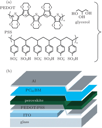
2. ExperimentAs shown in Fig. 1, the perovskite solar cells (PSCs) were fabricated with a configuration of indium tin oxide (ITO)/PEDOT:PSS/CH3NH3PbI3/PC61BM/Al. Patterned indium tin oxide(ITO)-coated glass with a sheet resistance of 15 Ω/square–20 Ω/square was cleaned by a surfactant scrub, then underwent a wet-cleaning process inside an ultrasonic bath, beginning with deionized water, followed by acetone and isopropanol. After oxygen plasma cleaning for 14 min, a 40-nm thick poly(3,4-ethylene- dioxythiophene):poly(styrene sulfonate) (PEDOT:PSS) (Bayer Baytron 4083) anode buffer layer was spin-cast onto an ITO substrate and then dried at 160 °C for 30 min. PbI2 and CH3NH3I were dissolved in N,N-dimethylformamide (DMF) and 2-propanol with concentrations of 400 mg·ml−1 and 30 mg·ml−1, respectively. The PbI2 solution was heated at 80 °C for around 20 min before use to make sure that PbI2 can be fully dissolved. The hot PbI2 solution was spun on the PEDOT:PSS substrates at 2000 rpm for 30 s. Then they were transferred onto a hot plate quickly and dried at 100 °C for 3 min. The CH3NH3I solution was spun on the tops of dried PbI2 films at 2000 rpm for 30 s at room temperature. The spin coated PbI2/CH3NH3I stacking films were then placed on the top of a hot plate that has been preheated at 100 °C in the ambient conditions. Around 25 μL of DMF solvent was added at the edge of a petri dish and quickly covered the perovskite layers to form the DMF vapor atmosphere. This annealing process continued for 1 h, leading to the formation of CH3NH3PbI3 layers of about 250 nm. Subsequently, the PC61BM solution was spin-coated over a perovskite layer at 1000 rpm for 40 s. Finally, a 100-nm Al layer was evaporated with a shadow mask in sequence in a vacuum chamber at a pressure of 6 × 10⁻⁵ Pa. The overlapping area between the cathode and anode determines a pixel size of 0.1 cm2. The thickness values of the evaporated Al were monitored by a quartz crystal thickness/ratio monitor ((SI-TM206, Shenyang Sciens Co.). Except for the deposition of the PEDOT:PSS layers, all the fabrication processes were carried out inside a controlled atmosphere in a nitrogen drybox (Etelux Co.) containing less than 1-ppm oxygen and moisture. The power conversion efficiencies (PCEs) of the resulting perovskite solar cells were measured under 1 sun, AM 1.5G (Air mass 1.5 global) condition using a solar simulator (XES-70S1, San-EI Electric Co.) with an irradiation of 100 mW·cm−2). The current density–voltage (J–V) characteristics were recorded with a Keithley 2400 source-measurement unit. The spectral responses of the devices were measured with a commercial EQE/incident photon to charge carrier efficiency (IPCE) setup (7-SCSpecIII, Bejing 7-star Opt. In. Co.). A calibrated silicon detector was used to determine the absolute photosensitivity.
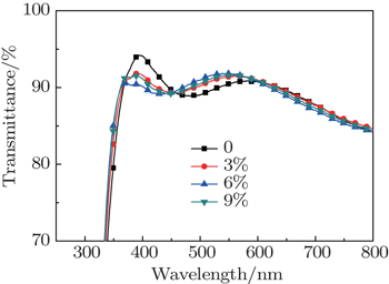
3. Results and discussion3.1. Effect of glycerol doping on transmittance of PEDOT:PSS filmTo better understand that the transparency of doped PEDOT:PSS thin film will influence the numbers of incident photons and photon-generated carriers on the perovskite layer, we test and compare the transparency values of the PEDOT:PSS thin films before and after doping four different glycerol concentrations; the results are shown in Fig. 2. It can be seen that the transparency of glycerol-doped PEDOT:PSS thin film declines slightly in the waveband between 370 nm and 450 nm; the transparency of glycerol-doped PEDOT:PSS thin film improves slightly in the waveband between 450 nm and 600 nm; the transparency of PEDOT: PSS thin film remains largely unchanged in the waveband between 600 nm and 800 nm. Since the average transparency of the whole thin film shows little change, there is no direct relationship between the performance improvement of a glycerol-doped PEDOT:PSS perovskite solar cell and the thin film transparency.
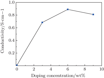
3.2. Effect of glycerol doping on conductivity of PEDOT:PSS filmFigure 3 shows the conductivities of glycerol-treated PEDOT:PSS films for various doping concentrations, which are measured by using the four-point probe technique; data for a pristine PEDOT:PSS film under the same conditions are also shown for comparison. Figure 3 follows that the electrical conductivity of the PEDOT:PSS thin film first increases, then decreases, with increasing glycerol content. The electrical conductivity of the PEDOT:PSS thin film without glycerol doping is 0.007 S/cm; the electrical conductivity of the PEDOT:PSS thin film with 3% glycerol doping reaches 0.684 S/cm; the electrical conductivity of the PEDOT:PSS thin film with 6% glycerol doping reaches 0.891 S/cm; however, further glycerol increase will result in a slight reduction of the electrical conductivity of the PEDOT:PSS thin film. Kim et al.[20] proposed that the conductivity enhancement is due to the fact that polar organic solvents with higher dielectric constant induce a screening effect between counter ions and charge carriers, which reduces the electrostatic interaction between positively charged PEDOT and negatively charged PSS, thereby enhancing the hopping rate in the PEDOT:PSS film. Meanwhile, Shin et al.[21] believed that the increased conductivities of the films in the presence of organic solvents arise from the rearrangement of the PEDOT:PSS morphology and PEDOT particle agglomerations occur, which leads to better connections between the conducting PEDOT chains.
3.3. Effect of glycerol doping on surface morphology of PEDOT:PSS filmAtomic force microscopy (AFM) is used to characterize the surface morphology of the PEDOT:PSS film as shown in Fig. 4. The bright regions in Fig. 4 are hard domains corresponding to PEDOT, whereas the dark regions denote the soft structure arising from PSS.[22] With glycerol doping, the PEDOT areas increase, while the PSS areas decrease, which is consistent with the conclusion that co-solvent addition results in both the decrease of energy barrier for electric charge transport on the PEDOT chain and the increase of delocalization length.[17] Meanwhile, the surface root-mean-square roughness value of the PEDOT:PSS films increases from 2.83 nm for the untreated film to 4.66 nm for the film treated for 9% glycerol. The increase in the surface roughness value may induce an increase in the effective contact area between PEDOT:PSS and the active layer. Therefore, the enlarged effective contact area possibly results in the enhancement of JSC.[21] Considering both the surface morphology and the current density, a critical doping ratio for PEDOT:PSS may exist as an optimum condition because the critical surface roughness may enable a more increased contact area between the PEDOT:PSS and perovskite layers. Moreover, rough surface facilitates light scattering and makes it possible to reflect the light back into the perovskite layer, thereby increasing light absorption.
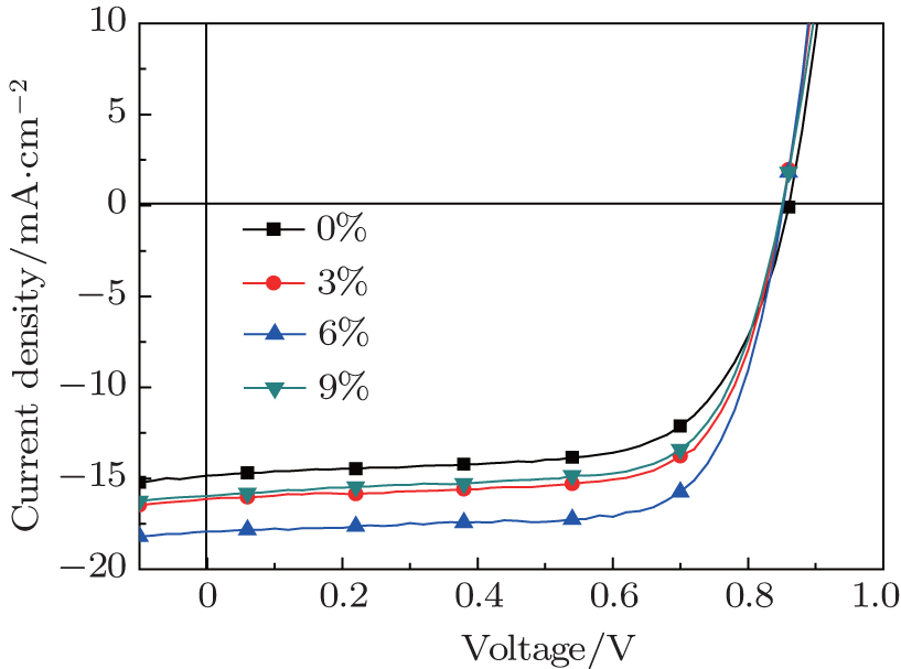
3.4. Effect of glycerol doping on photo current of solar cellsFigure 5 shows the current density–voltage (J–V) curves of fabricated solar cells with various glycerol doping ratios on PEDOT: PSS under the illumination of AM 1.5 G (air mass 1.5 global), 100 mW·cm−2 and with the scan rate of 10 mV/100 ms. Detailed information about JSC, VOC, FF, and PCE which are calculated from the J–V curves, is presented in Table 1. It can be seen that the photovoltaic performance is dramatically enhanced for the solar cells with glycerol-treated PEDOT:PSS films. When a 3-wt% concentration glycerol is doped, the device JSC increases from the original 14.85 mA·cm−2 (without glycerol doping) to 16.13 mA·cm−2; the device PCE increases from 8.57% to 9.66%; then, when the glycerol doping concentration increases to 6 wt%, JSC increased to 17.92 mA·cm−2, FF increased to 72.39%, and PCE increased to 11.03%, and the cell JSC and PCE increase respectively by 20.67% and 28.70% compared with those of the cell without glycerol doping. In addition, a reverse J–V scan is also given in Table 1. When a 6-wt% concentration glycerol is doped, the PCE of 11.41% is obtained and the hysteresis is negligible. The increase of the cell’s JSC mainly results from the performance change of the PEDOT: PSS thin film. The increase of electrical conductivity of glycerol doped PEDOT:PSS thin film leads to the decrease of the cell’s series resistance; hole carriers in the device tend to flow from the perovskite layer to the ITO anode through the PEDOT:PSS thin film. However, excessive glycerol doping will result in the serious separation of PEDOT:PSS, as well as the occurrence of more defects, which are unfavorable for the hole transport.[22] Hence, in a device where 9% glycerol is doped into PEDOT: PSS, the JSC and FF will both decrease.
Table 1.
Table 1.
 Table 1. Conductivity values and performances of the cells with different amounts of glycerol content. .
| Scan direction |
Glycerol content/wt% |
Conductivity/S·cm−1 |
VOC/V |
JSC/mA·cm−2 |
FF/% |
PCE/% |
RS/Ω·cm2 |
RSH/Ω·cm2 |
| Forward |
0 |
0.007 |
0.86 |
14.85 |
67.12 |
8.57 |
5.76 |
573.43 |
| Forward |
3 |
0.684 |
0.85 |
16.13 |
70.49 |
9.66 |
5.54 |
518.51 |
| Forward |
6 |
0.891 |
0.85 |
17.92 |
72.39 |
11.03 |
4.63 |
466.85 |
| Forward |
9 |
0.807 |
0.85 |
15.98 |
69.47 |
9.44 |
4.86 |
413.36 |
| Reverse |
0 |
0.007 |
0.86 |
15.19 |
67.35 |
8.80 |
5.35 |
617.24 |
| Reverse |
6 |
0.891 |
0.86 |
18.06 |
73.49 |
11.41 |
4.14 |
488.15 |
| Table 1. Conductivity values and performances of the cells with different amounts of glycerol content. . |
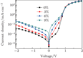
3.5. Effect of glycerol doping on dark currents of solar cellsTo gain an in-depth understanding of the improvement in device performance after treating with different doping concentrations of glycerol, the J–V characteristics of the devices in dark conditions are measured and shown in Fig. 6. Scans are taken from −2.0 V to 2.0 V, and the device area-normalized data are plotted on a logarithmic scale. The dark state current curve of the cell can reflect the changes of the cell’s series resistance (RS) and shunt resistance (RSH), and has an important reference value in evaluating the perovskite solar cell’s performance. The dark state curve of each solar cell can be divided into three regions:[24] in the low voltage region, there are symmetric small electric currents that are the leakage currents passing through the cell and are determined by RSH in the cell. With the increase of voltage, the positive current increases in an exponential manner, indicating that the device has rectifying properties of diode; with the further increase of the voltage, due to the tunnel effect and restrictions on space charge transport, the growth rate of electric current decreases,[25] and the electric current, which is determined by the RS in the cell at this time, is linearly related to with the voltage. The dark J–V curves in Fig. 6 show that the electric current increases after doping under forward bias, which means that the RS of the doped device decreases and is in accordance with the overall increasing trend of the electrical conductivity of doped-PEDOT:PSS thin film. With the increase of glycerol-doping concentration under reverse bias, the reverse saturation current of the device gradually increases, indicating that the RSH of the device decreases with the increase of glycerol-doping concentration, and the leakage current increases.
4. ConclusionsIn this paper, the influence of glycerol doped PEDOT:PSS thin film on the perovskite solar cell’s photovoltaic performance is studied. The glycerol doping improves the electrical conductivity of the PEDOT:PSS thin film: when the glycerol doping concentration is 6%, the electrical conductivity reaches 0.89 S/cm, which is 127 times larger than that of un-doped film. The JSC and PCE of the solar cell using a glycerol doped PEDOT:PSS anode buffer layer reach 17.92 mA·cm−2 and 11.03% respectively, which are raised by 20.67% and 28.70% compared with those of the un-doped device. It is due to the fact that the glycerol doping improves the electrical conductivity of PEDOT:PSS, resulting in the decrease of the total series resistance of the cell, and the hole carriers will flow from the perovskite layer to the ITO anode passing through the PEDOT:PSS thin film. Therefore, doping glycerol into the PEDOT:PSS is an effective method to improve the photovoltaic performance of perovskite solar cells.


 , Zhao Chuang, Zhang Heng, Tong Jun-Feng, Zhang Peng, Yang Chun-Yan, Xia Yang-Jun‡,