

Realization of a flux-driven memtranstor at room temperature
[Shen Shi-Peng, Shang Da-Shan†,  , Chai Yi-Sheng, Sun Young‡, ]
, Chai Yi-Sheng, Sun Young‡, ]
|
|


† Corresponding author. E-mail:
‡ Corresponding author. E-mail:
Project supported by the National Natural Science Foundation of China (Grants Nos. 11227405, 11534015, 11274363, and 11374347) and the Natural Science Foundation from the Chinese Academy of Sciences (Grant No. XDB07030200).
The memtranstor has been proposed to be the fourth fundamental circuit memelement in addition to the memristor, memcapacitor, and meminductor. Here, we demonstrate the memtranstor behavior at room temperature in a device made of the magnetoelectric hexaferrite (Ba0.5Sr1.5Co2Fe11AlO22) where the electric polarization is tunable by external magnetic field. This device shows a nonlinear q–φ relationship with a butterfly-shaped hysteresis loop, in agreement with the anticipated memtranstor behavior. The memtranstor, like other memelements, has a great potential in developing more advanced circuit functionalities.
Memristors, namely resistors with memory, have attracted much recent attention due to their ability to keep track of the past resistance state through which the element has experienced.[1–3] With inspiration from the discovery of memristor, the memory counterparts of capacitor and inductor, known as memcapacitor and meminductor, respectively, have also been proposed.[4] These circuit elements with memory, or memelement for short, when combined in complex circuit networks, can perform logic, arithmetic operation, and neuromophic computing in a massively parallel fashion, a striking resemblance with functionalities of human brain.[5–7] From symmetry concerns in circuit theory, there should a fourth fundamental circuit element in addition to the three well-known elements (resistor, capacitor, and inductor), which is defined directly from a relationship between charge q and magnetic flux φ. Accordingly, a memory counterpart to the fourth circuit element could also be conceived. The conjectured fourth memelement, in parallel to the memristor, memcapacitor, and meminductor, may further promote the functionalities of complex circuit networks, but has not yet been actualized in real devices.
Historically, the fourth fundamental circuit element was assigned to the memristor proposed by Chua in terms of the nonlinear i–v relationship with a pinched hysteresis loop,[8,9] as he was not aware of any device showing a direct φ–q relationship at that time. Nearly 40 years later, HP researchers demonstrated the memristor behavior in a metal/oxide/metal sandwiched structure that exhibits a hysteretic i–v curve.[10] This discovery spurred intensive interests in investigating resistance switching memories.[11,12] Furthermore, Chua argued that all the two-terminal nonvolatile memory devices based on resistance switching are memristors, regardless of the materials applied or physical mechanisms in operation.[13] However, it seems that the memristors based on resistance switching do not correlate charge q and magnetic flux φ directly as would expected for the fourth element by original definition. This point has been questioned by Vongehr et al. who recently claimed that the real memristor is still missing and likely impossible.[14] Also, Mathur commented that the memristor should not be the fourth element because of the absence of magnetic flux.[15]
Recently, a new fourth fundamental circuit element based on the magnetoelectric (ME) effects, dubbed transtor, has been proposed by us.[16] The ME effects refer to the change of electric polarization (magnetization) by applying a magnetic field (electric field), which have been observed in a variety of materials, especially multiferroic materials.[17,18] The transtor employing the ME effects can directly link q and φ by


The memory counterpart to transtor, dubbed memtranstor (MT), which can memorize the past dynamics between q and φ, has also been predicted[16] A memtranstor is defined by


 | Fig. 1. (a) The complete relational diagram of all the possible two-terminal fundamental circuit elements, each defined by a direct relationship between two basic variables. It consists of four linear elements, the resistor (R), the capacitor (C), the inductor (L), the transtor (T), and four nonlinear memelements, the memristor (MR), the memcapacitor (MC), the meminductor (ML), and the memtranstor (MT). Symbols for transtor and memtranstor are introduced to facilitate later usage. (b) Schematic illustration of the memtranstor behaviors. The butterfly-shaped hysteresis loop is expected to occur at a sufficiently large input of q or φ. |
The memristor, memcapacitor, and meminductor are always characterized by a pinched hysterestic loop dwelling in the I–III quadrants, due to the positive values of resistance, capacitance, and inductance, respectively. In contrast, the transtance defined in Eqs. (
Polycrystalline ceramics of the Y-type hexaferrite Ba0.5Sr1.5Co2Fe11AlO22 (BSCFAO) were prepared by solid-state reaction method. Stoichiometric amounts of SrCO3, BaCO3, Co3O4, Fe2O3, and Al2O3 were thoroughly mixed and ground together, calcinated at 940 °C in air for 10 h. The resulting mixture were reground, pressed into pellets, and fired at 1200 °C for 24 h in oxygen atmosphere. Subsequently, as-sintered samples were annealed in a flow of oxygen at 900 °C for 72 h and then slowly cooled down at a rate of 40 °C/h. The phase purity was checked by powder x-ray diffraction using a Rigaku x-ray diffractometer.
The BSCFAO sample was cut into a regular plate with a size of 2.36 mm × 2.36 mm × 0.39 mm and a mass of 0.012 g, and silver paste was painted on the widest faces as electrodes to form a simple two-terminal device. The magnetoelectric current and dielectric properties were measured by using an electrometer (Keithley 6517B) and an LCR meter (Aglient 4980A), respectively, in a Cryogen-free Superconducting Magnet System (Oxford Instruments, TeslatronPT). Before the measurement of magnetoelectric current, the device was poled in E = 5 kV/cm from 50 kOe (1 Oe = 79.5775 A·m−1) to 2 kOe to drive the sample from paraelectric to ferroelectric state. Then the poling electric field was cut off, and the current released from the electrods was measured as a function of scaning magnetic field. The magnetic properties were measured by using a superconducting quantum interference device magnetometer (Quantum Design MPMS-XL).
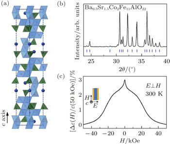
The hexaferrites are a family of old magnetic materials but are attracting renewed interests due to their strong ME effects arising from the ferroelectricity induced by the conical or helicoidal spin configurations.[19–24] Here, we utilize a Y-type hexaferrite with a nominal formula of Ba0.5Sr1.5Co2Fe11AlO22 (BSCFAO) that exhibits clear ME effects even at room temperature. The crystalline structure of the Y-type hexaferrites consists of alternate stacks of superposition of spinel blocks (S) and the so-called T-blocks with space group of R3m, as illustrated in Fig.
 | Fig. 2. (a) The crystal structure of the Y-type hexaferrite BSCFAO. (b) The XRD pattern of the polycrystalline BSCFAO samples at room temperature. The blue lines represent the standard peak positions. (c) The relative change of dielectric constant as a function of magnetic field at 300 K. The inset shows the measurement configuration. |
We then made a two-terminal device in which a thin plate of BSCFAO hexaferrite is sandwiched between two parallel silver electrodes to testify the memtranstor behavior. The magnetic field was applied along the in-plane direction and perpendicular to the electric field, forming a transverse magnetoelectric configuration (see the inset in Fig.
The magnetoelectric current was measured by sweeping H from 2 kOe to −2 kOe by passing through the zero-H continuously and then back again. Prior to the respective measurements, the device was poled from 50 kOe to 2 kOe with electric field E = 5 kV/cm to drive the sample from paraelectric to ferroelectric state. Figure


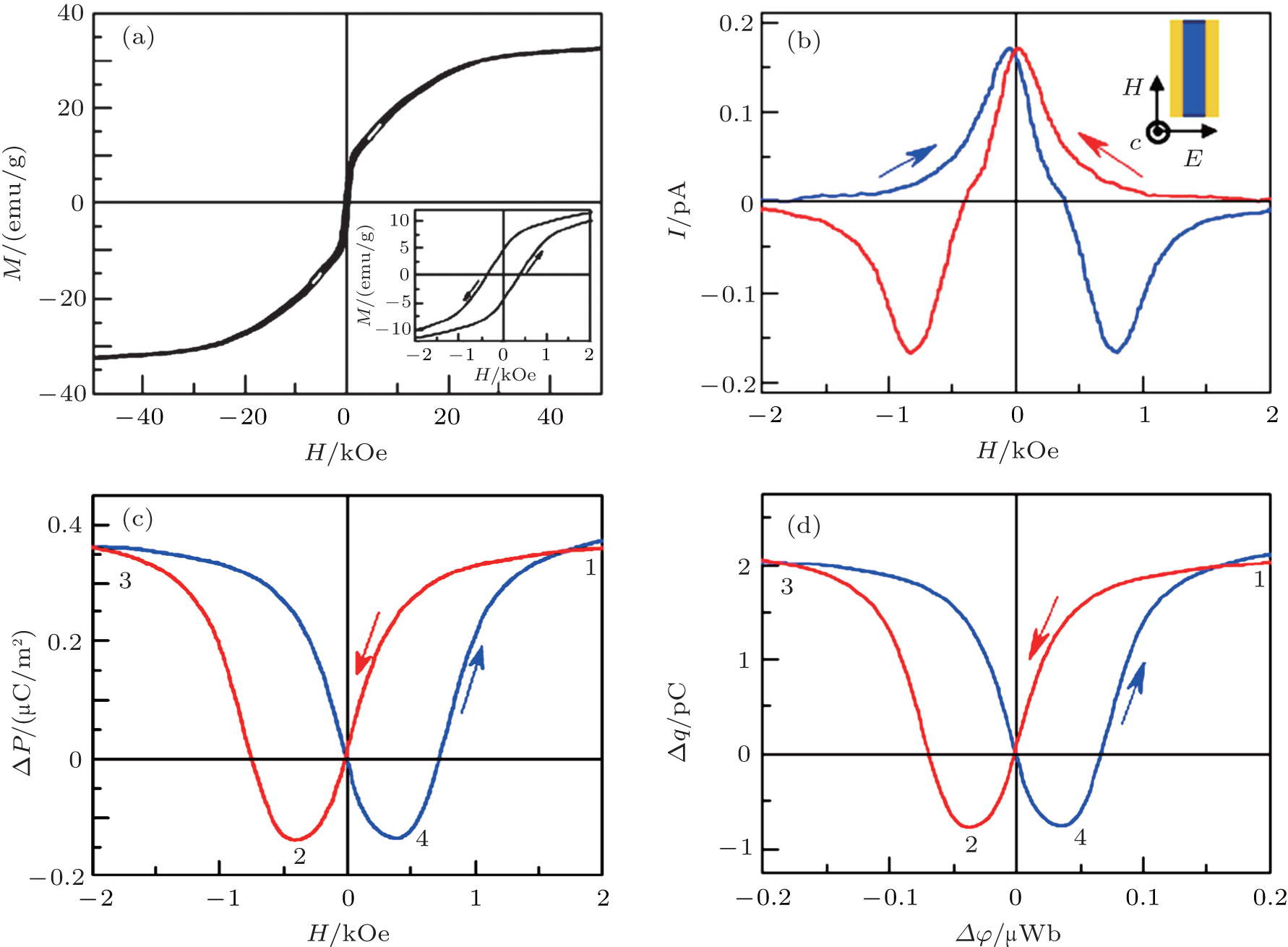 | Fig. 3. (a) The M–H hysteresis loop of BSCFAO at 300 K. The inset shows an expended view of the magnetization in the low-field region. (b) Magnetoelectric current at 300 K. The inset plots the scheme of the device and the measurement configuration. (c) Electric polarization as a function of magnetic field showing a butterfly-shaped hysteresis loop. (d) The corresponding Δq–Δφ relationship of the device. |
The microscopic origin of such spin-induced ferroelectricity can be successfully explained by the spin-current and the inverse Dzyaloshinskii–Moriya models.[28,29] This spontaneous electric polarization at moderate magnetic field can be attributed to transverse conical magnetic structure, just like previous results in other Y-type hexaferrites.[19–21] In traditional Y-type hexaferrites, the electric polarization P tend to be reversed by a small magnetic field H.[22–24] However, this transition in Y-type hexaferrites cannot generate butterfly-shaped ΔP–H curve because the sign of α is invariant if both P and H change their sign together. The unique property for the BSCFO ceramic used in this work is that the P is irreversible when sweeping H through zero field at room temperature. Therefore, the ΔP–H curve shows a butterfly-shape that is consistent to the anticipation for the memtranstor behavior (Fig.
In summary, we have successfully demonstrated the memtranstor behavior in a real device made of a magnetoelectric hexaferrite (BSCFAO) at room temperature. This BSCFAO material exhibits a strong nonlinear magnetoelectric effect at room temperature so that an applied magnetic field is able to change the electric polarization in a nonvolatile way. This results in a nonlinear q–φ relationship of the device with a special butterfly-shaped hysteresis loop, in agreement with the anticipated memtranstor behavior. The memtranstor, regarded as the fourth fundamental circuit memelement after the memristor, memcapacitor, and meminductor, will have a great promise in generating more advanced circuit functionalities and should deserve extensive studies in the future.
| 1 | |
| 2 | |
| 3 | |
| 4 | |
| 5 | |
| 6 | |
| 7 | |
| 8 | |
| 9 | |
| 10 | |
| 11 | |
| 12 | |
| 13 | |
| 14 | |
| 15 | |
| 16 | |
| 17 | |
| 18 | |
| 19 | |
| 20 | |
| 21 | |
| 22 | |
| 23 | |
| 24 | |
| 25 | |
| 26 | |
| 27 | |
| 28 | |
| 29 | |
| 30 | |
| 31 |