A hybrid mode of one- and two-surface multipactor on grooved dielectric surface
Cai Li-Bing1, 2, Wang Jian-Guo1, 2, †, , Cheng Guo-Xin2, Zhu Xiang-Qin2
Key Laboratory for Physical Electronics and Devices of the Ministry of Education, Xi’an Jiaotong University, Xi’an 710049, China
Northwest Institute of Nuclear Technology, Xi’an 710024, China


† Corresponding author. E-mail: wanguiuc@mail.xjtu.edu.cn

Project supported by the National Natural Science Foundation of China (Grant No. 61231003).

Abstract
Abstract

A hybrid mode of one- and two-surface multipactor on the grooved dielectric surface is studied in detail using both an analytical approach and two-dimensional particle-in-cell (2D PIC) simulations. When the groove width L < eE0/(4πme f2), there are one-surface multipactor and one-order two-surface multipactor on the grooved dielectric surface, and only one slope of the groove has the multipactor anytime. When L > eE0/(4πme f2), both slopes may have the multipactors. The electron surface density of the multipactor discharge has a sharp increase at the length L = eE0/(4πme f2).

1. Introduction

The multipactor is a vacuum surface discharge mainly due to the secondary electron emission (SEE). It is often destructive, and it can occur in a wide variety of scenarios, such as radio frequency (RF) windows, accelerator structures, or satellite communication devices.[13] Its suppressing has been a major concern in the fields of high-power microwave sources, RF accelerators, and space-based communication systems.[47] As is well known, the multipactor includes two modes, i.e., one-surface mode and two-surface mode. The former often occurs on the RF window surface or insulator surface, requires an applied electric field parallel to the dielectric surface and a direct current (DC) electric field from the charging of the dielectric surface, and has been profoundly investigated experimentally, theoretically, and numerically.[821] The latter requires a resonant RF electric field perpendicular to the plate surface, and often occurs on the waveguide or metal gap.[1,22] Despite the extremely similar physical process, they are always thought to occur on different devices solely and are studied by researchers from different fields separately.

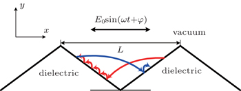
In this paper, we present a novel form of the multipactor discharge, a hybrid mode of one- and two-surface multipactors on a periodic grooved dielectric surface by using a two-dimensional (2D) self-consistent particle-in-cell (PIC) simulation.[2326] Grooving on the dielectric surface is a common multipactor suppression method which can change the electrons’ trajectories.[4,5] For the triangular groove, the hybrid multipactor discharge occurs in the triangular gap between two slopes of the groove, as shown in Fig. 1. As the RF electric field has a component parallel to the dielectric surface, the one-surface multipactor will occur on the slope. And the multipactor electrons will move towards the adjacent slope through the gap when the RF electric field direction changes. When the electrons reach the adjacent slopes, but the RF electric field direction does not change again, i.e., the electron flight is not resonant with the RF electric field, the electrons will participate in the one-surface multipactor on the adjacent slope until the RF field direction changes again. This means this hybrid multipactor does not require a strict resonant RF field, and if the transit time of electrons is greater than half of the RF period, the two-surface and one-surface multipactor can occur on two slopes respectively, which is very unfavorable to the suppression effect of the groove.

Fig. 1. Schematic diagram of electron orbits on the grooved surface.
2. Physical model and numerical results

Compared with the planar surface, it is much easier for the primary seed electrons to impact with the non-planar surface. Thus, the SEE avalanche is unavoidable if the SEE yield of the dielectric material is greater than 1. Owing to the surface charge effect, the SEE reaches a balanced state subsequently, i.e., saturated multipactor. Hence, the analysis in this paper will focus itself on the saturated multipactor. The RF electric field is Erf = E0 sin(2π ft + φ)x, where E0 is the amplitude of the RF field, f is the RF frequency, and φ is the primary phase. The groove width is L. For the RF field with zero primary phase, the RF electric field is along the x direction and a one-surface multipactor would occur on the front slope at odd half-periods. At even half-periods, the RF electric field is along the –x direction, the one-surface multipactor will occur on the rear slope. For the multipactor electrons on the front slope, the direction of the RF electric field changes from the x direction to the –x direction at t = (n + 1/2)T (n = 1, 2, 3,…), and the electrons begin to move to the rear slope. We assume that the velocities of electrons are all 0 at t = (n + 1/2)T (the electron has a small initial velocity along the x direction in fact). Then, the motion of the multipactor electron on the rear slope is governed by

where a(t) is the acceleration in the x direction, x(t) is the x displacement, while e and me are the charge and mass of electron, respectively. After odd half-periods, the x displacement is equal to keE0/(4πme f2) along the –x direction. Here, k is the number of half-periods. If the groove width L, i.e., the maximum width of the triangular gap, is smaller than one half-period displacement eE0/(4πme f2), there is only the one-order two-surface multipactor on the grooved surface; if L is greater than eE0/(4πme f2), there will be the resonant or high-order two-surface multipactor, and more than two electron clusters exist in the gap. Owing to the space charge effect between the electrons, the detailed value of the half-period displacement will have a discrepancy, and besides the x movement forced by the RF electric field, the electron also has a –y displacement forced by the electrostatic field, which is produced by the positive surface deposited charge on the two slopes. For the multipactor electron on the front slope, the motion is symmetrical to the electron on the rear slope, and has one half-period difference in time from the electron on the rear slope.

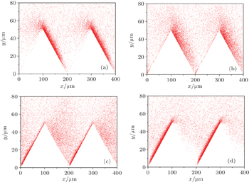
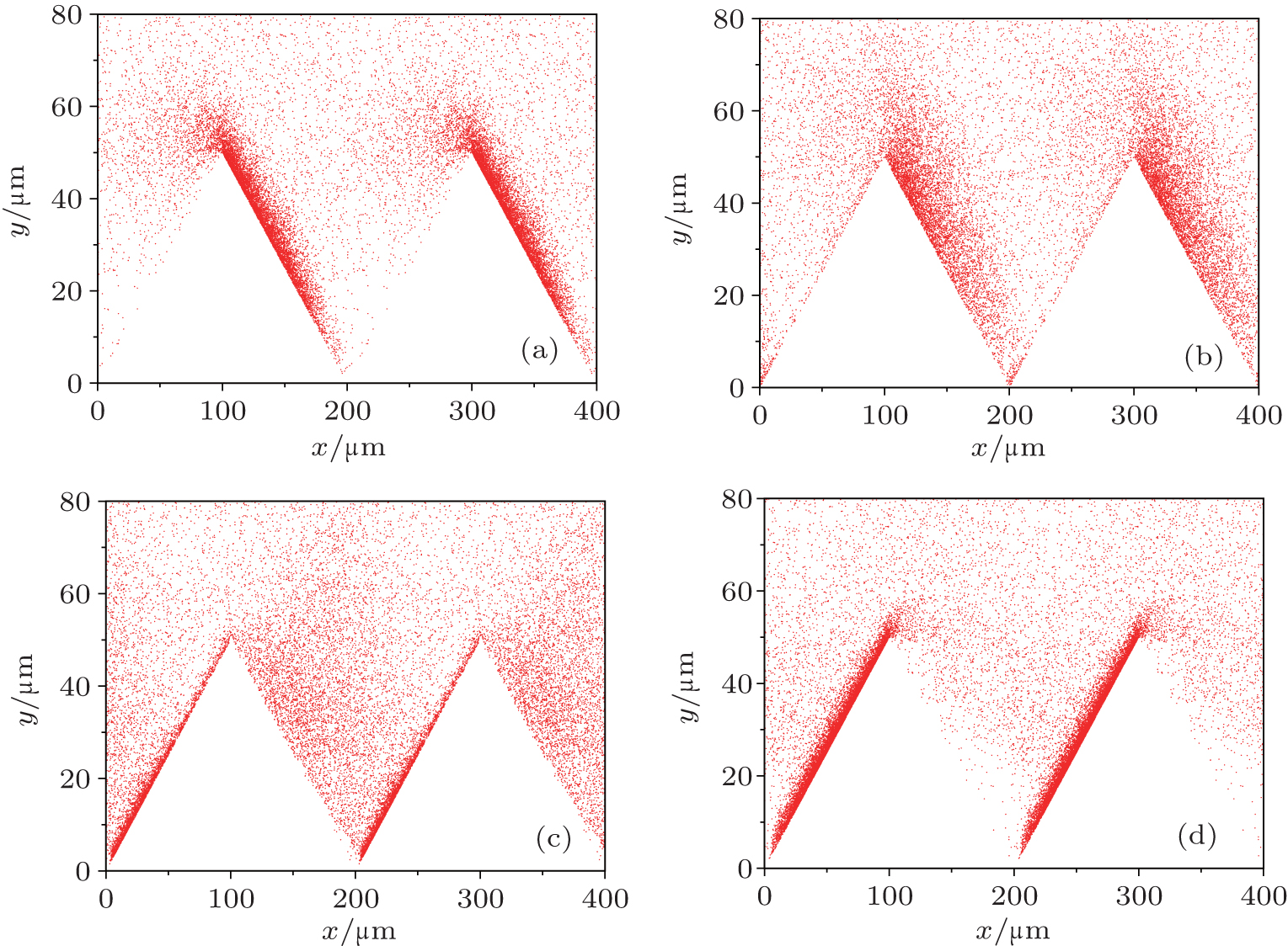
Fig. 2. Space distributions of electrons at (a) (n − 1/2)T, (b) (n − 3/8)T, (c) (n − 1/4)T, and (d) (n − 1/8)T.

As an example, this analysis is applied to the discharge under the RF field with f = 10 GHz and E0 = 3 MV/m. In this case, the corresponding half-period displacement is 419.75 μm. The groove height is 50 μm, which is greater than the motion height of most multipactor electrons on the planar surface. The groove width L is 200 μm, which is about only 1/2 of the half-period displacement, i.e., the transit time of the electrons is smaller than the RF half-period. Thus, the one-surface mode and one-order two-surface mode both exist. At t = (n − 1/2)T, the multipactor on the front slope stops, and the electrons will begin to turn around and move towards the rear slope. At the same time, the one-surface multipactor on the rear slope starts, and the electrons appear subsequently. As the smaller length is at the bottom of the gap, the electrons from the front slope reach the rear slope earlier as shown in Fig. 2(b). At t = (n − 3/8)T, the one-surface multipactor becomes obvious and the two-surface multipactor electrons cross the gap. At t = (n − 1/8)T, most two-surface multipactor electrons finish the transition, and the one-surface multipactor on the front slope dominates the discharge. It can be found that there are two electron clusters at most, i.e., the transiting electrons from the front slope and the one-surface multipactor electrons on the rear slope. During each one-half period, the multipactor could take place either on the front slope or the rear slope. This means that the multipactor on almost half the dielectric surface is suppressed by the groove.

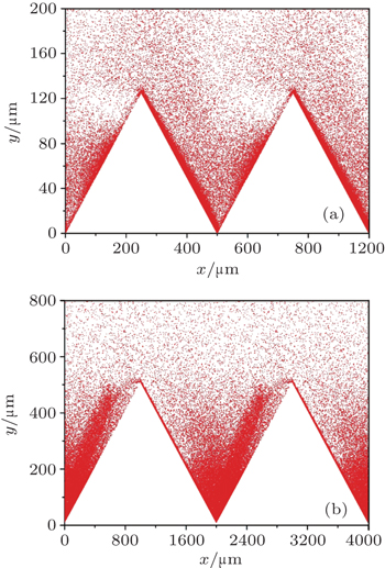
When the groove width is near to the electron half-period displacement, the electron transit time is about T/2. The multipactor electrons leaving the rear slope at t = (n − 1)T reach the front slope at t = (n − 1/2)T, and impact the front slope with the transit energy, i.e., the resonant two-surface multipactor may occur. Those electrons mix with the one-surface multipactor electrons from the front surface flying toward the rear slope as shown in Fig. 3(a). At the same time, the rear slope satisfies the condition for a multipactor, that is, the RF electric field is in the –x direction and forces the electrons to move towards the rear slope. Therefore, there are three electron clusters and both slopes have multipactor discharges at most. If the gap length goes on increasing, more higher-order two-surface multipactor and electron clusters will appear as shown in Fig. 3(b). Owing to the space charge effect, the electron clusters diffuse with the transit time, and cannot be distinguished from each other clearly after the long transit time. In Fig. 3(b), only the electron cluster leaving the rear slope can be identified distinctly. Meanwhile, as the electron transit has a downward velocity, there will be an electron accumulation at the bottom of the gap, and the accumulation degree will be aggravated with the increase of the groove width.

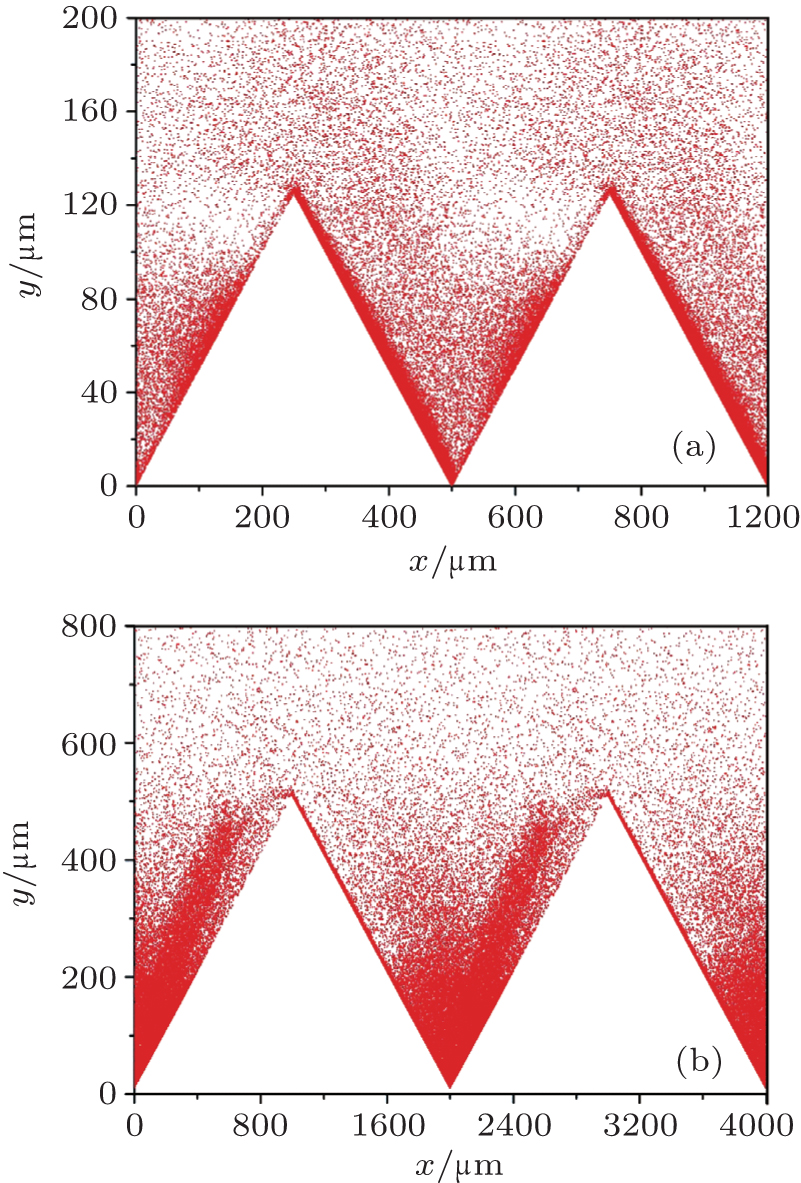
Fig. 3. Space distributions of electrons at (a) L = 500 μm and (b) L = 2000 μm.

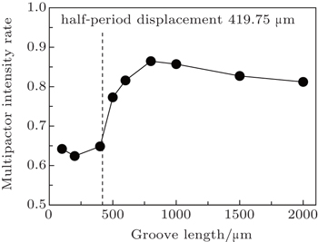
The existence of the two-surface multipactor will increase the multipactor intensity. Figure 4 shows the ratio of the multipactor electron surface density on the grooved surface to that on the planar surface, and it can be seen from this figure that the peak electron density has a sharp increase near the half-period displacement eE0/(4πme f2). The electron densities are about 65% and 85% of the density on the planar surface if the grooved width is smaller and greater than the half-period displacement, respectively. Therefore, to obtain a more effective suppression of the multipactor discharge, the groove width L should be smaller than eE0/(4πme f2).

Fig. 4. Peak surface density of multipactor electron versus groove length.
3. Conclusions

In this work, the model and simulations presented in this paper provide a hybrid mode of one- and two-surface discharges on a grooved dielectric surface. The saturated multipactor electrons transit back and forth in the triangular gap. Because the two-surface multipactor electrons also may join the one-surface multipactor while the RF electric field is not resonant, the two-surface mode on the groove is not sensitive to a resonance condition. Therefore, the one-order two-surface mode cannot be avoided. However, the resonance of the two-surface modes can be avoided when the groove period length L < eE0/(4πme f2). In this case, there is only one slope that has a multipactor discharge and one electron cluster transiting in the gap. If L exceeds eE0/(4πme f2), both the slopes may have multipactors and more electron clusters will appear and the intensity of the multipactor discharge will have an obvious increase.

Besides the triangular groove, other shaped grooves, such as the rectangular groove, also present a suppression effect on the multipactor. Therefore, we are now improving the simulation code, and more shaped surfaces will be considered in the next code. At the same time, the electron-stimulated outgassing will also be involved for a more comprehensive study of dielectric surface breakdown.

Reference
1Vaughan J1998IEEE Trans. Electron Dev.351172
2Miller H C 1989 IEEE Trans. Electrical Insulation 24 765
3Anderson R ABrainard J P 1980 J. Appl. Phys. 51 1414
4Chang CLiu G ZHuang H JChen C HFang J Y 2009 Phys. Plasmas 16 083501
5Chang CHuang H JLiu G ZChen C HHou QFang J YZhu X XZhang Y P 2009 J. Appl. Phys. 105 123305
6Ivanov O ALobaev M AIsaev V AVikharev A L 2010 Phys. Rev. ST Accel. Beams 13 022004
7Sazontov A GNevchaev V E 2010 Phys. Plasmas 17 033509
8Kishek R ALau Y Y 1998 Phys. Rev. Lett. 80 193
9Ang L KLau Y YKishek R AGilgenbach R M 1998 IEEE Trans. Plasma Sci. 26 290
10Kim H CVerboncoeur J P 2005 Phys. Plasmas 12 123504
11Kim H CVerboncoeur J P 2006 Phys. Plasmas 13 123506
12Cai L BWang J G2009Acta Phys. Sin.583268(in Chinese)
13Wang J GCai L BZhu X QWang YXuan C 2010 Phys. Plasmas 17 063503
14Chang CLiu G ZTang C XChen C HFang J Y 2011 Phys. Plasmas 18 055702
15Cai L BWang J GZhu X QWang YXuan CXia H F 2011 Phys. Plasmas 18 073504
16Liu X HHe WYang FWang H YLiao R JXiao H G 2012 Chin. Phys. B 21 075201
17Kishek R A 2012 Phys. Rev. Lett. 108 035003
18Cheng G XLiu L 2013 Appl. Phys. Lett. 102 243506
19Dong YDong Z WYang W YZhou Q HZhou H J2013Acta Phys. Sin.62197901(in Chinese)
20Dong YZhou Q HYang W YDong Z WZhou H J2014Acta Phys. Sin.63185206(in Chinese)
21Zhao P CLiao CYang DZhong X M 2014 Chin. Phys. B 23 055101
22Kryazhev ABuyanova MSemenov VAnderson DLisak MPuech JLapierre LSombrin J 2002 Phys. Plasmas 9 4736
23Cai L BWang J GZhang D HDu T JZhu X QWang Y 2012 Phys. Plasmas 19 073516
24Wang JZhang DLiu CLi YWang YWang HQiao HLi X 2009 Phys. Plasmas 16 033108
25Cai L BWang J GCheng G XZhu X QXia H F 2015 J. Appl. Phys. 117 053302
26Wang JWang YZhang D 2006 IEEE Trans. Plasma Sci. 34 681