Cycloid motions of grains in a dust plasma
[Zhang Yong-Liang, Feng Fan, Liu Fu-Cheng, Dong Li-Fang, He Ya-Feng†,  ]
]
]
|
|


† Corresponding author. E-mail:
Project supported by the National Natural Science Foundation of China (Grant Nos. 11205044 and 11405042), the Natural Science Foundation of Hebei Province, China (Grant Nos. A2011201006 and A2012201015), the Research Foundation of Education Bureau of Hebei Province, China (Grant No. Y2012009), the Program for Young Principal Investigators of Hebei Province, and the Midwest Universities Comprehensive Strength Promotion Project.
Hypocycloid and epicycloid motions of irregular grains (pine pollen) are observed for the first time in a dust plasma in a two-dimensional (2D) horizontal plane. These cycloid motions can be regarded as a combination of a primary circle and a secondary circle. An inverse Magnus force originating from the spin of the irregular grain gives rise to the primary circle. Radial confinement resulting from the electrostatic force and the ion drag force, together with inverse Magnus force, plays an important role in the formation of the secondary circle. In addition, the cyclotron radius is seen to change periodically during the cycloid motion. Force analysis and comparison experiments have shown that the cycloid motions are distinctive features of an irregular grain immersed in a plasma.
The dust plasma is characterized by charged grains immersed in a plasma of electrons and ions.[1–3] The grains could acquire charges of the order of 103 to 104 elementary charges and often become strongly coupled, which gives rise to novel phenomena such as the crystallization, phase transitions, and waves.[4–9] The grains suspended in sheath suffer gravitation force, electrostatic force, drag force, and sometime external magnetic/laser field etc. It leads to complex motions of grains like gyromotion, cluster rotation and shear flow.[10–17] It is obvious that a charged grain could perform gyromotion if it is magnetized in external magnetic field. The measurements of gyroradius and cyclotron frequency provide an effective method for the noninvasive determination of the charge on a grain.
Most of studies on the dust plasma either in experiment or in theory deal with grain of a spherical form, such as the glass, melamine formaldehyde, and alumina mocrosphere.[3–5] In some cases, especially in the numerical simulation of molecular dynamics, for simplicity, the grain is considered as a charged particle neglecting the grain shape. However, the grains appeared in planetary rings, fusion reactors, materials processing, etc., generally have a nonspherical shape. The dynamics of the nonspherical grain in the dust plasma is less known at present.
A grain immersed in a plasma suffers the momenta transferred from plasma flux and surrounding gas.[1–3] This could result in the spin of the grain and has been paid much attention in recent years.[18–20] For an ideal spherical grain, the net effect for the momenta transfer can be zero. For a grain with irregular shape the net transfer of the angular momenta can be estimated as ηassπ a2ni,∞miavsv∞[18] (where ηass is the coefficient taking into account the degree of irregularity of the dust shape, a is the average radius of the grain, ni,∞ is the ion density, mi is the ion mass, vs is the ion velocity at the surface of the grain when they are attached to the grain and v∞ is the ion velocity far from the grain). The angular frequency of such spin can reach a rather large value (∼104 s−1–109 s−1).[19] The spin of a hollow glass microsphere with defect has been detected with angular velocity up to 12000 rad/s in a stratified glow discharge.[19] The spin of a charged grain could give rise to a magnetic moment. Interacting with external magnetic field, the spinning grain is subjected to a magnetic force which could result in the complex motions of such grain.[18,21] However, in the absent of external magnetic field, a spinning grain could also exhibit complex motions which have not been well studied until now. Here, we report an experimental study on the cycloid motions of irregular grains (pine pollen) in a dusty plasma. Hypocycloid and epicycloid motions are observed, besides the stationary grain and the circle motion of grain. The inverse Magnus force originated from the spin of the grain is considered, and it plays important role on the cycloid motions of grains. These complex motions of grains are explained based on the force analysis in 2D horizontal plane. Additional comparison experiments with regular microspheres are performed in order to confirmed that the cycloid motions are distinctive features of a pine pollen immersed in a plasma.
Figure
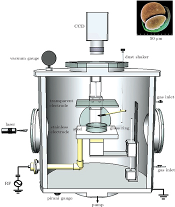
 | Fig. 1. Schematic diagram of the experimental setup. The inset shows the image of a pine pollen we used in experiments. |
Pine pollen having nonspherical shape as shown by the inset in Fig.
A glass ring is positioned on the lower stainless steel electrode. The diameter and the height of the glass ring are 37 mm and 10 mm, respectively. After being injected into the plasma, charged grain levitates nearby the glass wall. Due to the circular symmetry of the glass ring the grain travels around the glass ring or stays near its equilibrium position.
We firstly show the regular movement of a single grain around the glass ring in a 2D horizontal plane as shown in Fig.

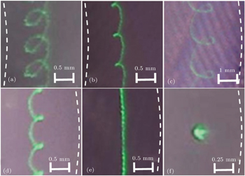
 | Fig. 2. Trajectories of travelling (a)–(e) and stationary (f) grains. Dashed line in each image indicates schematically the glass ring. Panels (a) and (b) are located outside the glass ring. Panels (c)–(f) are located inside the glass ring. (a): epicycloid motion; (b): cuspate epicycloid motion; (c): hypocycloid motion; (d): cuspate hypocycloid motion; (e): circular motion; (f): stationary grain. Exposure times of panels (a)–(f) are: 0.39, 0.26, 0.53, 0.16, 0.32, 1 s, respectively. |
Cuspate epicycloid and hypocycloid motions are observed as shown in Fig.

Circular motion is observed both inside and outside the glass ring as shown in Fig.
Which trajectory a grain will follow is determined by the initial conditions (such as the initial position and the angular velocity) of the dropped grain and the discharge parameters. This means that for several grains dropped simultaneously (or one grain dropped repeatedly), they (it) will exhibit different trajectories because their (its) initial conditions are not exactly the same. Therefore, the dependencies of the parameters r1,2 and ω1,2 mentioned above on the gas pressure and the forward power of discharge could not be illustrated evidently. In our experiments, the radii of the primary and the secondary circles change within the ranges of r2 = 0.08 mm–0.57 mm and r1 = 13 mm–25 mm, respectively. The corresponding values of angular velocities change within the ranges of ω2 = 24 rad/s–88 rad/s and ω1 = 0.03 rad/s–0.63 rad/s, respectively.
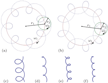
 | Fig. 3. Schematic diagram of cycloid motions. (a): epicycloid; (b): hypocycloid. Dotted line represents the trajectory of cycloid motions of grains. Solid line and dashed line indicate the primary circle and the secondary circle, respectively. r2 and r1 represent the radii of the primary and the secondary circles, respectively. ω2 and ω1 represent the angular velocities of the primary and the secondary circles, respectively. Panels (a) and (b) occur when ω1ω2 > 0 and ω1ω2 < 0, respectively. Panels (c)–(f) reproduce the trajectories as shown in Figs. |
The (cuspate) cycloid motions of grains follow the parameter equations in polar coordinate if we pick the center of glass ring as the origin:


The force analysis for a nonspherical grain, like the pine pollen we used, becomes very complex. These forces mainly include the gravitation force, electrostatic force, ion drag force, neutral friction force, and inverse Magnus force. The inverse Magnus force, which originates from the spin of a nonspherical grain, is considered here for the first time. The interaction force between grains is not considered in the present case because only one or few grains separated well are dropped in each experiment.
The gravitation force Fg = mg acts downward vertically and will not be considered here because our emphases is on the horizontal motions of dust grains.
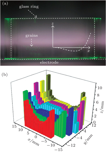
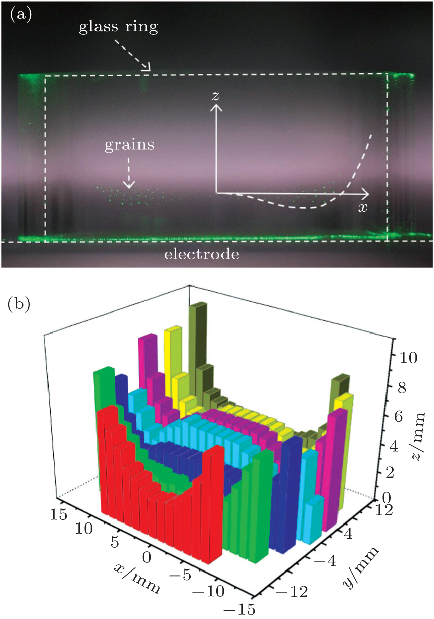 | Fig. 4. Sheath profile indicated by the grain distribution in x–z plane at y = 0 mm (a) and in three-dimensional (3D) space (b). Radial profile of the sheath inside the glass ring is indicated by the dropped grains illuminated by a vertical laser sheet. Gas pressure is 15 Pa and forward power is 8 W. |
The electrostatic force originates from the action of sheath field on the negatively-charged grain. In the present of a glass ring the sheath profile follows approximately the walls of the glass ring and the electrode. Because the thickness of sheath near the glass ring and the electrode are different,[26] the confinement of the sheath to the grain becomes complex. When the diameter of the glass ring is small, the horizontal confinement to the grain could be described by a parabolic potential, and the grain is confined to the center of the glass ring.[3] Here, the glass ring is relatively large, and the grain is restricted near the glass wall both inside and outside. In order to obtain the radial distribution of the sheath, we drop plenty of grains into the glass ring and capture the grain distribution in x–z plane illuminated by a vertical laser sheet as shown in Fig.

Ion drag force acting on the grain by ion flow results mainly from Coulomb drag and collection drag, and has been explored extensively. Together with the neutral drag and the plasma charging flux, the ion drag could give rise to the spin of the immersed grain. The spin of a hollow transparent glass microsphere with surface defect was observed in a stratified glow discharge by Karasev et al.[19] The values of angular velocity measured in their experiments are between 0 and 12000 rad/s. As a rule, for the nonspherical grain as we used here, the pine pollen would spin faster than the glass microsphere they used because the surface of pine pollen is much irregular than that of glass microsphere. The rapid spin of the pine pollen around its center of inertia gives rise to the inverse Magnus force which plays important role on the complex motions of grains.
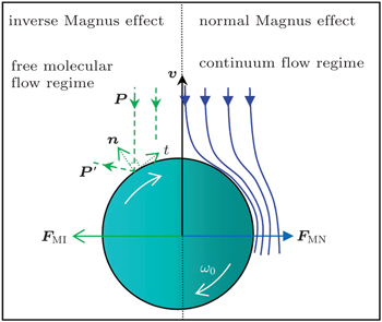
The inverse Magnus force results from the spin of a travelling grain in rarefied fluid as illustrated by Fig.

 | Fig. 5. Schematic diagram of the inverse (normal) Magnus force |
The neutral drag force is a resistance force caused by the collisions with the neutral gas molecules. It damps the motion of grain. Therefore a driving force is necessary for the grain to keep moving forward along the orbit. Although the origin of this unknown driving force is still unclear at present, we can give some suggestions. 1) It should be related with the irregularity of the grain, because our comparison experiments with glass and resin microspheres have shown that no cycloid motion and no circle motion are observed. Several groups also reported the rotation of nonspherical agglomerate of microspheres. The rotation of microsphere is observed only in a magnetized dust plasma, which is induced by the Lorentz force.[6,13] 2) This driving force is nondirectional with regard to the glass ring because both clockwise and counterclockwise rotations are observed. 3) It should be the same order of magnitude of the neutral drag force because the grain could continue to move uniformly along the glass ring. In the following we will neglect the counteractive neutral drag force and driving force.
The cycloid motion of the grain is characteristic of a combination of the primary and the secondary circles. Therefore, the essential origins of the primary and the secondary circles are keys to understand the formations of these cycloid motions.
For a charged grain travelling along the primary circle in a plasma, a persistently centripetal force is required. As is well known, the Lorentz force and the inverse Magnus force are characteristic of their transverse action with respect to the travelling direction of an object. However, no magnetic field is applied to the charged grain in our experiments. Therefore, only the inverse Magnus force appears and provides the persistently centripetal force for the rotation of the grain along the primary circle. Other forces mentioned above cannot provide persistently centripetal action on the travelling grain. For example the horizontal components of the electrostatic force and ion drag force act only in radial direction due to the rotational symmetry of the glass ring. Although those forces are not the origin of the primary circle, they play important role in the formation of the secondary circle.
The spin of the irregular charged grain is the key to the cycloid motion via inverse Magnus effect. In order to confirm these distinctive features of the cycloid motions the pine pollen has exhibited as shown above, further experiments with glass and resin microspheres are performed at the same discharge conditions for comparison (not shown here). No cycloid motion is observed. Those regular microspheres (less spin) show behaviours such as the random motion and the crystallization as other groups observed previously. Therefore, we can draw a conclusion that the spin of the pine pollen gives rise to the inverse Magnus force which provides the centripetal force for the primary circle.
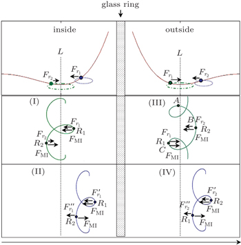
Our observations of the cycloid motions of grains can be classified roughly into four groups (I)–(IV) as shown by the diagrams in Fig.
 | Fig. 6. Schematic diagram of the grain trajectories. Solid lines in panel (a) illustrate the approximate profile of sheath in vertical section. Equilibrium line L (dashed line) indicates the position of the minima value of confining potential. F1 represents the horizontal component of the radially confining force when the grain is between the equilibrium line L and the glass wall. Outside this region, it is expressed as F2. Panel (b) shows four cases of complex trajectories in a horizontal plane. (I), (II), and (IV) show the hypocycloid motions, and (III) shows the epicycloid motion. FMI represents the inverse Magnus force. R1 (R2) is the cyclotron radius when the grain is near (far away from) the glass wall. |
For the case (III), the grain meanders near the equilibrium line L. The centripetal forces at points B and C read:


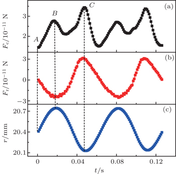
The centripetal force Fc consists of inverse Magnus force FMI and radial confinement force Fr as shown by Eqs. (
 | Fig. 7. Dependance of the centripetal force Fc = mv2/r (a), the radially confining force Fr = mar (m: grain mass, ar: radial acceleration) (b), and the radial position r (c) of grain on time. These measured results correspond to the grain outside the ring which follows the epicycloid trajectory as shown by Fig. |
The above force analysis is also applicable to the case (I). However, because the small cyclotron radius R1 is located outside the equilibrium line L in case (I), the periodical change of the cyclotron radius results in the hypocycloid trajectory as illustrated by Fig.
For the case (II), the grain meanders between the equilibrium line L and the glass wall. The centripetal forces near and far away from the glass wall are:


In this work, we have studied the cycloid motions of irregular grains (pine pollen) in a dusty plasma in a 2D horizontal plane. Hypocycloid motions are observed both inside and outside the glass ring. Epicycloid motion is observed only outside the glass ring. The radially confining potential from the sheath is experimentally measured, which play important role in the formation of cycloid motions of grains. Based on the force analysis and the measured trajectories of grain with high speed camera, the inverse Magnus force is obtained to be of the order of 10−11 N, and the value of the angular velocity is of the order of 105 rad/s. The observed cycloid motions of grains result from the periodical change of the cyclotron radius near and far from the glass wall. Additional comparison experiments with regular microspheres are performed in order to confirmed that the cycloid motions are distinctive features of a pine pollen immersed in a plasma.
Recently, some studies focused on the Magnus effect in optical manipulation,[29] in a Bose–Einstein condensate,[30] and in lattice models of superfluids.[31] They have revealed that the Magnus force is larger than that predicted by theoretical models and allows one to perform particle trapping. Our results have also revealed that the Magnus effect an irregular grain exhibited in plasma environment can not be negligible and would play important role on the complex motions of the grains. It is also suggested that these complex motions of irregular grains we observed could be found in fusion reactors because the grown or sputtered grain could have considerable angular speed of spin.
In addition, the vector of angular velocity of a spinning grain is not limited to the vertical direction as we discussed above. Due to the stochastic initial conditions of a dropped grain, this vector could point at other directions in three dimensional space. This means that the inverse Magnus force acting on a spinning grain could point out of the horizontal plane. Therefore, the inverse Magnus force together with the other forces will give rise to more complex motions of grains in three dimensional space. This will be the subject of a future study.
| 1 | |
| 2 | |
| 3 | |
| 4 | |
| 5 | |
| 6 | |
| 7 | |
| 8 | |
| 9 | |
| 10 | |
| 11 | |
| 12 | |
| 13 | |
| 14 | |
| 15 | |
| 16 | |
| 17 | |
| 18 | |
| 19 | |
| 20 | |
| 21 | |
| 22 | |
| 23 | |
| 24 | |
| 25 | |
| 26 | |
| 27 | |
| 28 | |
| 29 | |
| 30 | |
| 31 |