
Underwater asymmetric acoustic transmission structure using the medium with gradient change of impedance
[Hu Bo1, 2, Shi Jie1, 2, †,  , Shi Sheng-Guo1, 2, Sun Yu1, 2, Zhu Zhong-Rui1, 2]
, Shi Sheng-Guo1, 2, Sun Yu1, 2, Zhu Zhong-Rui1, 2]
|
|


† Corresponding author. E-mail:
Project supported by the National Natural Science Foundation of China (Grant Nos. 11204049 and 11204050), the Program for Changjiang Scholars and Innovative Research Team in University of Ministry of Education of China (Grant No. IRT1228), and the Specialized Research Fund for the Doctoral Program of Higher Education of China (Grant Nos. 20122304120023 and 20122304120011).
We propose an underwater asymmetric acoustic transmission structure comprised of two media each with a gradient change of acoustic impedance. By gradually increasing the acoustic impedances of the media, the propagating direction of the acoustic wave can be continuously bent, resulting in allowing the acoustic wave to pass through along the positive direction and blocking acoustic waves from the negative one. The main advantages of this structure are that the asymmetric transmission effect of this structure can be realized and enhanced more easily in water. We investigate both numerically and experimentally the asymmetric transmission effect. The experimental results show that a highly efficient asymmetric acoustic transmission can be yielded within a remarkable broadband frequency range, which agrees well with the numerical prediction. It is of potential practical significance for various underwater applications such as reducing vibration and noise.
The electrical diode, the first man-made device enabling a rectifying current flux, has eventually led to substantial worldwide revolution. Many considerable efforts have been made to rectify other kinds of energy fluxes in a similar manner.[1–4] Li and Wang[3] presented the fundamental model of a thermal diode that has a rectifier effect on thermal energy. The thermal rectifying effects as well as the rectifying effects of solitary waves have been identified both theoretically and experimentally.[4] Recently, Liang et al. have numerically demonstrated a theoretical model of an acoustic diode and presented the first experimental demonstration of a rectified energy flux of acoustic waves by coupling a superlattice with a strong nonlinear medium.[5–7] It is noteworthy, however, that this working mechanism of nonlinear medium unavoidably leads to the problem of inefficient and unstable conversion acoustic energy conversion. Considering this problem in nonlinear media, many efficient linear structures have been proposed to transfer acoustic waves in the one-way direction.[8–11] Zhu et al.[8] have investigated theoretically the broadband structure of one-dimensional phononic crystal (PC) plates which present Lamb wave one-way mode transmission in certain frequency bands. Yuan et al.[9] have designed a two-dimensional model of a broadband directional acoustic waveguide with a linear PC to yield direction-dependent transmission properties for incident waves. Li et al.[10] have proposed a scheme of realizing broadband asymmetric acoustic transmission by utilizing PC-based materials with a gradient sound speed distribution. Additionally, inspired by the phenomenon that the propagating direction of acoustic waves can be continuously bent to follow a sinusoidal trajectory in the gradient-index PC, some studies have demonstrated the acoustic mirage or acoustic beam aperture modifier by using a gradient-index PC structure.[12,13] In practice, however, it is difficult for most of the underwater acoustic systems to use PC because of the restriction on water pressure and dimension, which means that these models cannot be applied to underwater engineering application. Therefore, it is necessary to explore the possibility of underwater asymmetric acoustic transmission structures which use other gradient-index acoustic materials.
In this work, we build a one-dimensional model of an underwater asymmetric acoustic transmission by utilizing the media each with a gradient change of impedance. It shows that asymmetric acoustic transmission can be achieved in a broadband frequency range. The design of the model is detailed in Section 2. Some numerical simulations are carried out and the typical results are obtained in Section 3. The media each with a gradient change of impedance is obtained by the precipitation method, and the performance of the proposed structure is verified experimentally in Section 4. A summary and discussion is given in Section 5.
Consider a model, composed of three parallel regions, as shown in Fig. (a) Schematic illustration of the model of underwater asymmetric acoustic transmission by utilizing the media each with a gradient change of impedance. The contrasty color denotes the distribution of specific acoustic impedance. The rigid (absorptive) boundary is denoted by gray (red) color. (b) The sketch map of the transmission of an acoustic wave incident from positive direction (gray arrow) and negative direction (blue arrow).
The rectangle ABCD is the first medium with acoustic impedance Z varying from Z0 to Zmax in the x direction, such that Z(xA) = Z0 and Z(xD) = Zmax (Zmax > Z0), i.e., there are the matched impedance and no step changes in the impedance at the boundary. Zmax is the acoustic impedance of the medium at surface CD. There is no variation of specific acoustic property in the y direction. On the other hand, the trapezia CDEF is the second medium with acoustic impedance varying from Zmax to Z0 along the positive x axis. The angle θ is the angle between EF and negative direction of y direction. The boundary BF and AD are chosen and made of rigid materials, and the boundary DE is assumed to be an ideal absorptive boundary. A plane wave is horizontally incident along the x axis, initiated in region I or region III. We generally define the propagating direction of acoustic wave incident from region I as the positive direction and incident from region III as the negative one.
The basic mechanism of asymmetric acoustic transmission in this model is briefly addressed here. As is well known, when the sound speed mismatch exists between two different media, an oblique incidence acoustic wave is refracted at the interface. The amount of wave beam bending is dependent on the sound speed difference according to Snell’s law. When a plane wave is incident from the positive direction, owing to the continuous distribution of acoustic impedance inside region II and the matched impedance with water at the boundary, the acoustic wave does not backscatter and can propagate along a straight line through region II. Although the angle θ leads to the impedance difference between the second medium and region III at the interface of EF because of the gradient profile only changing along the x axis, the trajectory of output acoustic wave is almost not bent due to the small angle θ. It means that the acoustic waves can pass through the model along the positive direction. On the other hand, when the acoustic wave is incident from the negative direction, the acoustic impedance of the second medium increases along the negative x axis. Therefore, at any interface parallel to CD, the refraction angle is always larger than the incidence angle. Thus, the propagating trajectory of the acoustic wave in the second medium can be continuously bent approximately parallelly to CD. Finally, all of the acoustic waves from the negative direction will reach the boundary DE, resulting in being absorbed by the absorptive boundary (see Fig.
Our design is derived by employing the theory of geometric acoustics, which is a better understanding of how to change the trajectory of acoustic wave in this model. By calculating the sound speed contribution in the medium, one can readily predict the direction of refraction using Snell’s law.[14] Meanwhile, the ray-acoustic theory is helpful in predicting the position of acoustic ray. The acoustic ray equation is given by[15]


To examine the performance of the model described in the preceding section, a simulation study has been carried out. In the numerical simulation, boundary AD and CF are both set to be 0.1 m, the length of boundary CD is 0.05 m, and θ = 30°. Regions I and III are homogeneous water with mass density ρ0 = 1500 kg/m3, and sound speed c0 = 1000 m/s. Considering the realization of the medium with a gradient change of impedance in practice, the acoustic impedances and the sound speeds of two media are chosen as
We first study the acoustic ray trajectories along the two sides of the model. It is noticeable that the medium in the trapezium CDEF plays a chief role in changing the direction of the incident wave. Thus, figure Acoustic ray trajectories along the positive direction and the negative one.
Figure
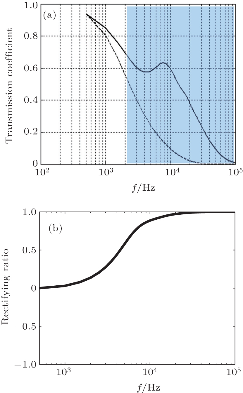 | Fig. 3. (a) Calculated total transmission coefficients of acoustic waves that are incident from the positive (solid line) direction and the negative (dashed line) direction, respectively. The significant difference is denoted by using the blue region. (b) The rectifying ratio of the model within a broadband frequency range. |
To estimate the effect of the asymmetric acoustic transmission we introduce the concept of rectifying ratio that is defined as RC=(TL − TR)/(TL+TR), where TL and TR are the transmissions along the positive and negative directions, respectively. Notice that the rectifying ratio describes the relative quantity of two transmission coefficients. Thus, as RC is equal to 1 or −1, the whole system may obtain the best effect of one-way transmission along the positive direction or the negative one. Conversely, the fact that RC equal to 0 shows that the asymmetric acoustic transmission does not exist. Figure
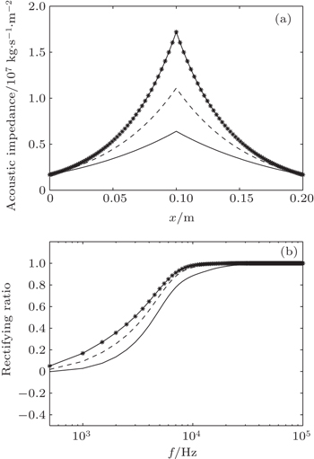
It is understandable that the distribution of acoustic impedance should have a direct effect on the acoustic characteristic of this structure. Thus, in order to further verify the feasibility of this model, it is necessary to choose specific acoustic impedance in an optimal manner and study the relationship between the gradient profile of impedance and asymmetric acoustic transmission. Figure
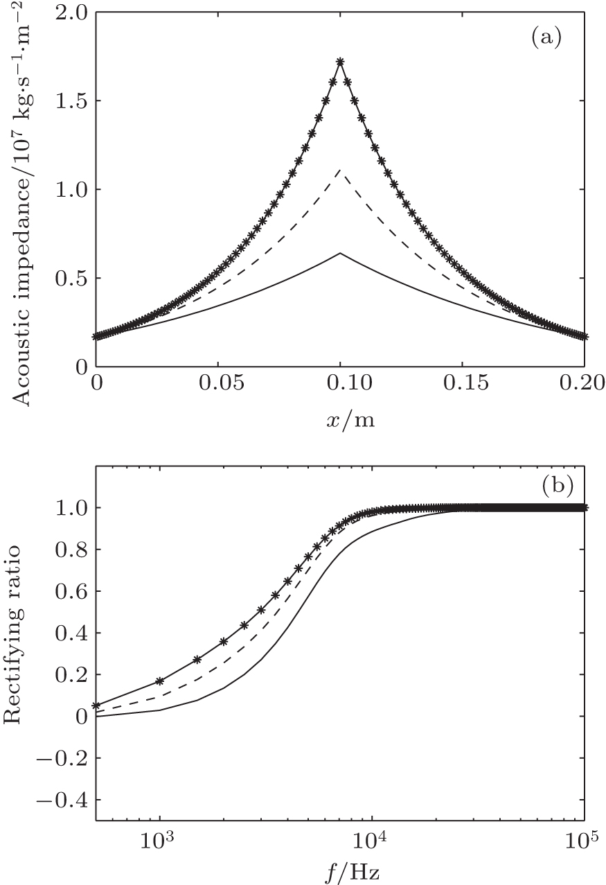 | Fig. 4. (a) Typical gradient profiles of acoustic impedance for three cases: Zmax = 6.4 × 10⁶ kg/(s·m2), 1.1 × 10⁷ kg/(s·m2), and 1.7 × 10⁷ kg/(s·m2). The solid line, dashed line, and dotted line refer to the three cases (from bottom to top), respectively. (b) Comparison of rectifying ratio among the three cases (from bottom to top). |
In Fig.
In order to verify the validity of the proposed asymmetric acoustic transmission structure, an experiment has been carried out by measuring the total transmission of acoustic waves that are incident from the two sides of the structure. In the present study, the medium with gradient change of impedance was prepared by the precipitation method. The details of the procedure are as follows.
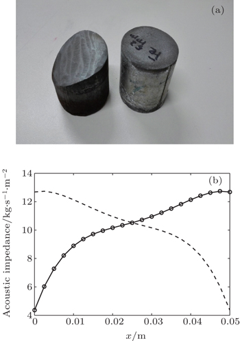
The mixed metal powder and polymer binder were employed as the materials. The polymer adhesive is the mixture of phenolic resin and urotropine each with an appropriate quantity. A mixture of mixed metal powder and polymer binder was heated while continuously stirring for 30 min in a beaker. For the synthesis of individual medium, precipitation reactions were carried out using water in a plastic tube and the mixture was quickly added into it to form a mixture solution. In theory, the precipitant with different solubility products will lead to a sequential sediment process, which finally leads to precipitant particles with gradient structure. During the precipitation, a black precipitate formed, which was removed from a plastic tube and dried at 80 ° C in an oven for 2 h. The precipitates were uniaxially pressed with a pressure of approximately 80 MPa to form samples and the prepared samples were calcined at 200 ° C for 2 h inside a muffle furnace. Two cylindrical media that had the same gradient profiles of impedance were prepared with 5-cm thickness and 5.5-cm diameter. Figure
 | Fig. 5. (a) Prepared media each with a gradient change of impedance. (b) Distributions of acoustic impedance of two prepared media. The dotted–solid line and dashed line refer to the first medium and the second medium as shown in Fig. |
It needs to be mentioned that due to the limited preparation technology, it is difficult to solve the intersolubility problem of the mixed metal powder and polymer solubility binder, which leads to the phenomenon that samples are easy to fracture after being calcined. Therefore, the intersolubility values of different materials and the hardness values of prepared samples were comprehensively considered. Ensuring the acoustic impedance of the medium is continuously changing, the acoustic impedance of the prepared medium increased. Figure
Figure
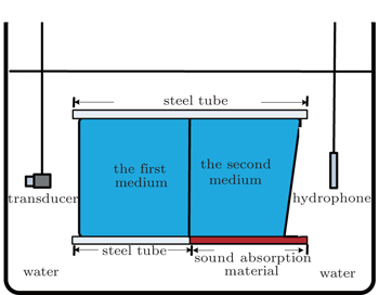
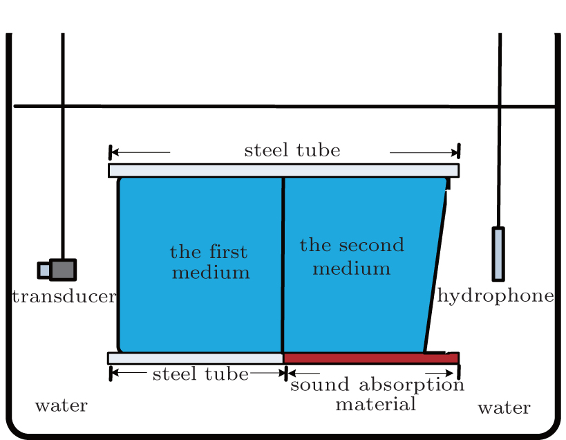 | Fig. 6. Cross-sectional configuration of the asymmetric acoustic transmission structure composed of two media each with a gradient change of impedance and schematic diagram of the experimental measurement system. The two media each refer to the medium with a gradient change of impedance denoted by using the blue region. The gray region represents the steel tube containing two prepared media. The red region represents the sound absorption material. A transducer and a hydrophone are chosen as the transmitter and the receiver. |
An experiment is conducted in an anechoic pool. The structure is clamped and placed between a transducer (type UAT-20W) and a hydrophone (type TC4035) which are chosen as the transmitter and the receiver, respectively. A directional transducer with ± 6° directivity angle is chosen to reduce the influences of reflection and diffraction. The emission surface of the transducer is placed vertically to the tube with a distance of 20 cm, in which the propagating acoustic waves could be regarded as plane waves. On the other side, the hydrophone is set around the tube with 2 cm. The signal is generated by the Agilent33522A signal generator for driving the transducer, and it is passed through an AR150 power amplifier. The measuring and analysis equipment also contain a B&K2636 measuring amplifier and a PULSE 3560 analyzer system.
Two transmission coefficients of acoustic waves incident from the positive direction (solid line) and the negative direction (dashed line) are measured when the amplitude of acoustic wave signal is 150 mV as shown in Fig.
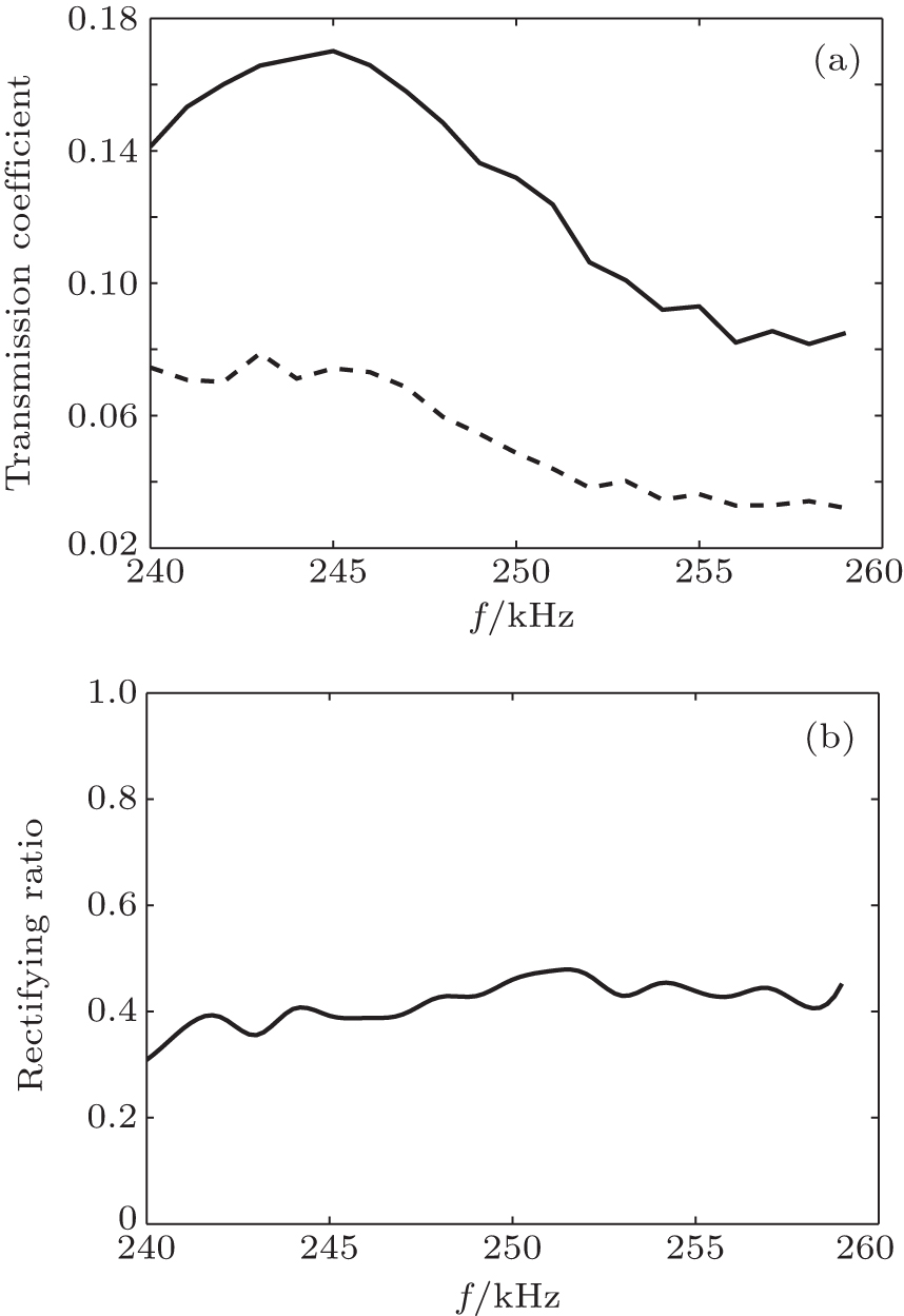 | Fig. 7. (a) Experimental results of total transmission coefficients of acoustic waves that are incident from the positive (solid line) direction and the negative (dash line) direction, respectively, when the amplitude of acoustic wave signal is 150 mV. (b) Measurement results of rectifying ratio of the proposed asymmetric acoustic transmission structure. |
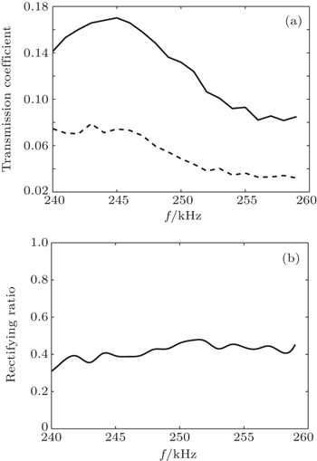
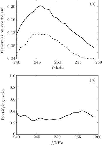
To illustrate the frequency dependences of the acoustic transmissions, we further analyze the experimental results when the amplitude of the acoustic wave signal is 200 mV. It can be more clearly visualized that the obvious difference and rectification effects appear in Fig.
 | Fig. 8. (a) Experimental results of total transmission coefficients of acoustic waves that are incident from the positive (solid line) direction and the negative (dashed line) direction, respectively, when the amplitude of the acoustic wave signal is 200 mV. (b) Measurement results of rectifying ratio of the proposed asymmetric acoustic transmission structure. |
In this paper, we present an underwater asymmetric acoustic transmission structure by using the medium with a gradient change of impedance. The model of asymmetric acoustic transmission is established and the basic mechanism is investigated based on the acoustic ray theory and transfer-matrix method. The simulation results reveal that the proposed structure can yield a satisfactory broadband asymmetric acoustic transmission. The characteristic of asymmetric acoustic transmission is sensitive to the gradient profile of acoustic impedance. The medium of gradient change of impedance is prepared by the precipitation method. The experimental results verify the validity and efficiency of the proposed structure, and agree well with the numerical predictions. Therefore, this asymmetric acoustic transmission structure has potential applications in various underwater practical situations such as weakening vibration and reducing noise, filters, and transducers.
| 1 | |
| 2 | |
| 3 | |
| 4 | |
| 5 | |
| 6 | |
| 7 | |
| 8 | |
| 9 | |
| 10 | |
| 11 | |
| 12 | |
| 13 | |
| 14 | |
| 15 | |
| 16 |