


Tunable acoustic radiation pattern assisted by effective impedance boundary
[Feng Qian1, 2, Li Quan1, 3, Li-Wei Wang1, Xiao-Zhou Liu1, †,  , Xiu-Fen Gong1]
, Xiu-Fen Gong1]
|
|


† Corresponding author. E-mail:
Project supported by the National Basic Research Program of China (Grant Nos. 2012CB921504 and 2011CB707902), the National Natural Science Foundation of China (Grant No.11474160), the Fundamental Research Funds for Central Universities, China (Grant No. 020414380001), the State Key Laboratory of Acoustics, Chinese Academy of Sciences (Grant No. SKLOA201401), the Priority Academic Program Development of Jiangsu Higher Education Institutions, and the Scientific Research Foundation for the Returned Overseas Chinese Scholars, State Education Ministry.
The acoustic wave propagation from a two-dimensional subwavelength slit surrounded by metal plates decorated with Helmholtz resonators (HRs) is investigated both numerically and experimentally in this work. Owing to the presence of HRs, the effective impedance of metal surface boundary can be manipulated. By optimizing the distribution of HRs, the asymmetric effective impedance boundary will be obtained, which contributes to generating tunable acoustic radiation pattern such as directional acoustic beaming. These dipole-like radiation patterns have high radiation efficiency, no fingerprint of sidelobes, and a wide tunable range of the radiation pattern directivity angle which can be steered by the spatial displacements of HRs.
The research on abnormal light propagation, such as extraordinary optical transmission (EOT) or directional beaming through a subwavelength metallic aperture or slits, has attracted increasing interest in the last decade.[1–8] Like the optical counterparts, the enthusiasm of studies about manipulating the acoustic wave is on the rise.[9–23] Recently there were breakthroughs in acoustic metamaterials.[24–27] Specifically, the active acoustic metamaterials were proposed, such as using active devices to break the reciprocity for nonreciprocal acoustics.[28–30] Acoustic radiation pattern control has now gathered widespread attention in recent years due to its various application prospects in medical ultrasound instrumentation, secure communication, etc. In common cases, the acoustic wave will diverge in propagation, owing to the diffraction effect. Besides, the directivity of radiation pattern will fall off with the decrease of frequency. In order to save transmitted energy or retain the confidence of the signals, manipulating directional radiation is needed.
The pioneering work by Lu et al. on the transmission of an impinging acoustic wave through a one-dimensional acoustic grating with subwavelength apertures has proved an effective way to excite the phenomenon of extraordinary acoustic transmission (EAT).[9] By investigating the beam from a subwavelength slit surrounded by periodic grooves, Christensen et al. successfully obtained a collimated wave,[10] which was experimentally demonstrated by Mei et al.[11] The underlying physics of EAT phenomenon is already intensively studied nowadays, which is mostly attributed to the contribution of acoustic surface evanescent wave (ASEW) and the interplay of the waveguide modes inside the apertures.[12,13] Based on wave-vector analysis, a theoretical model of tunable directional acoustic beaming assisted by surface acoustic wave (SAW) has been proposed by using asymmetric surface gratings.[14] Though these on-axis sound beams have good collimation effects, the fundamental mechanism inevitably brings many unwanted sidelobes into the radiation pattern. Recently, instead of adjusting the material properties throughout the propagation region,[15–17] regulating surface impedance has been demonstrated as another valid way to manipulate radiation patterns.[18–23] Owing to the presence of designed inhomogeneous impedance, steerable extraordinary reflection can be achieved.[18,19] Meanwhile, the manipulation of EAT has been achieved through tuning structure topology or acoustic metasurface impedance.[20–22] By optimizing surface impedances, our team has successfully obtained a dipole-like radiation pattern from a subwavelength slit, which conveys sound energy directly into the front region.[23] Extending our previous studies of the surface impedance which is identical on both sides in the scheme, it naturally leads to the question of what we will obtain by breaking the surface impedance symmetry.
In this paper, we propose a scheme to tune the direction of an acoustic beam. As the boundary acoustic impedance can be changed by introducing Helmholtz resonators (HRs), we find that it is possible to obtain an inhomogeneous impedance boundary by rearranging the HRs. Using this method, asymmetric surface impedances can be obtained, which will result in a tunable directional radiation pattern.
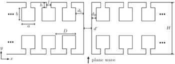
The proposed structure consists of a subwavelength slit surrounded by two metal plates on both sides, whose surfaces are decorated with HRs. The schematic configuration is given by Fig.
 | Fig. 1. Schematic diagram of subwavelength slit surrounded by two metal plates decorated with Helmholtz resonators (HRs). |
Firstly, we survey the underlying mechanism of the effective impedance boundary caused by HRs. Without HRs, the specific acoustic impedance of a metal surface can be regarded as being infinite, ZS → ∞, owing to a large difference between air and steel. Once the HR is introduced, on a subwavelength scale, the effective impedance of the region boundary can be expressed as


From these above equations, it is easy to deduce that arbitrary surface impedance can be obtained with optimized designed HRs size. In other words, we are capable of changing the original boundary into the desired condition with different HRs. Of course, the sizes of HRs should be within the practical working limits. In particular, when frequency meets the resonance condition, 

Without loss of generality, we assume that dL is the only control variable which contributes to the radiation pattern manipulating effect, and the configuration on the right side remains unchanged in the discussion. Full-wave simulations using finite-element method (FEM) are presented to verify our scheme. The parameters of the sample are set to be as follows: D = 8 mm, dR = 1.5 mm, d′ = 2 mm, h = 0.5 mm, l = 1 mm, a = b = 5 mm, and H = 36 mm. The frequencies of incident acoustic plane waves are all set to be f = 8600 Hz, and the corresponding wavelength should be λ = c0/f ≈ 39.9 mm. Since the period of HRs is much smaller than the wavelength, the premise of Eq. (

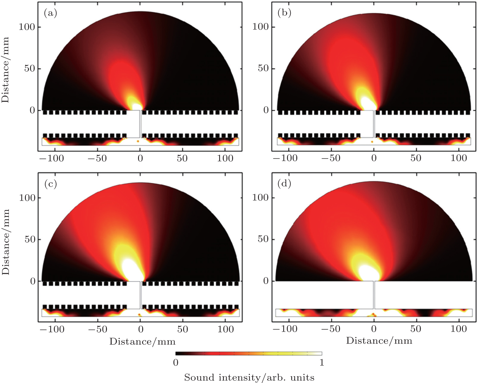
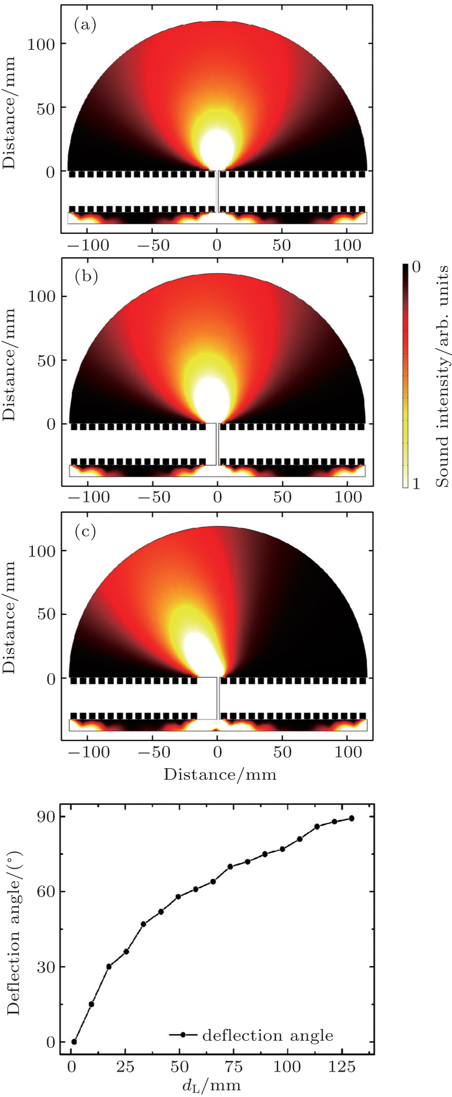 | Fig. 2. ((a)–(c)) Simulated results of intensify patterns of a plane wave passing through the sample at f = 8600 Hz when dL = 1.5 mm, 9.5 mm, and 17.5 mm, respectively. (d) The beam deflection angle as a function of the distance between the left side-line of the slit and the HRs. |
Comparing our study with the existing EAT or tunable beam manipulation schemes, one thing that should be mentioned is that our scheme is not just narrow-banded, i.e., the radiation pattern can occur in a relatively wide frequency range, which is demonstrated in Figs.
 | Fig. 3. (a)–(c) Simulated results of intensity patterns of a plane wave passing through the sample when f = 8300 Hz, 8400 Hz, 8500 Hz, respectively when giving dL = 9.5 mm. (d) Simulated result of intensity pattern of a plane wave passing through the undecorated sample when giving a specified impedance value at f = 8600 Hz. |
The underlying mechanism is the effective impedance boundary caused by optimized HRs that contributes to these exotic radiation patterns, not the excitation of the SAW by inducing surface gratings. To confirm this, figure 
There are two reasons that need to be pointed out, which can explain the subtle differences between Figs.
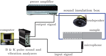
An experiment is conducted to further confirm the influence of asymmetric distribution of HRs on the radiation pattern directivity. The experiment is carried out in the anechoic chamber in order to eliminate the influence of the reflected waves. To avoid the diffraction from the edge of the sample, a sound insulation box is used. The pressure signal is picked up by a free-field 1/2-inch (1 inch, = 2.54 cm) microphone, which is fixed in a stepper motor controlled by the computer. The 3560B Brüel & Kjær Pulse Sound and Vibration Analyzer is used to generate output signals and collect input signals. The schematic diagram of experimental set-up can be found in Fig.
 | Fig. 4. Schematic diagram of experimental set-up of asymmetric effective impedance boundary. |
The sample is made of steel, whose material parameters are as follows: mass density ρ = 7800 kg/m3, Young’s modulus E = 21.6 × 10¹⁰ N/m2, Poisson’s ratio σ = 0.28, and sound speed c = 5200 m/s. The total width, height and thickness of each metal sample are 128 mm (containing 16 units, if decorated with HRs), 25 mm and 36 mm respectively. To avoid the complexity of sample processing, we choose dL to be very large (dL → ∞) and dR = 1.5 mm. In other words, the left sample has no HRs, while the right one is full of HRs as shown in Fig.
 | Fig. 5. (a) Top views of the sample fabricated by asymmetric distribution of periodical HRs and a single slit in the center (scale bar: 40 mm). (b) Experimental and (c) simulated results of intensity patterns of a plane wave passing through the sample. |
Figures
Owing to the presence of HRs, the effective impedance boundary or surface condition can be adjusted. By rearranging the HRs, asymmetric impedance boundaries surrounding a subwavelength slit are obtained, which plays a key role in producing the tunable acoustic radiation pattern. The feasibility of the proposal is verified by both simulation and experimental results. Compared with existing methods, our proposed scheme presents the radiation patterns with no sidelobes nor surface acoustic waves caused by structure, which conserves most of the acoustic energy in the main lobe. The low complexity facilitates the proposal realization and application. We believe that the enthusiasm of numerous research studies of effective impedance boundary is just starting and prospective applications of directional radiation in the fields such as secure communication or ultrasonic medical instrument would be expected.
| 1 | |
| 2 | |
| 3 | |
| 4 | |
| 5 | |
| 6 | |
| 7 | |
| 8 | |
| 9 | |
| 10 | |
| 11 | |
| 12 | |
| 13 | |
| 14 | |
| 15 | |
| 16 | |
| 17 | |
| 18 | |
| 19 | |
| 20 | |
| 21 | |
| 22 | |
| 23 | |
| 24 | |
| 25 | |
| 26 | |
| 27 | |
| 28 | |
| 29 | |
| 30 |