Experimental study of the dependences of retrieval efficiencies on time delay between magneto-optical-trap being turned off and optical storage
The State Key of Quantum Optics and Quantum Optics Devices, Institute of Opto-Electronics, Shanxi University, Taiyuan 030006, China
† Corresponding author. E-mail: wanghai@sxu.edu.cn
Project supported by the National Basic Research Program of China (Grant No. 2010CB923103) and the National Natural Science Foundation of China (Grant Nos. 11475109, 11274211, and 60821004).
1. IntroductionAn elementary task in a quantum repeater is to build entanglement between two nodes.[1–5] Such a task may be realized by mapping entangled two-photonic qubits in two atomic ensembles, respectively, and storing them for a desired time interval.[3–5] The dynamic electromagnetically induced transparency (EIT) process[6–8] in an atomic ensemble allows one to coherently transfer the quantum state between photons and spin waves,[9–11] and has been developed into an effective optical quantum storage method.[12,13] Using an EIT-based storage scheme, Choi et al. have established entanglement between two quantum memories stored in cold atomic ensembles.[5]
The entangled state between two photonic qubits A and B can be expressed by ψ = c1 |1〉A |0〉B + c2 |0〉A |1〉B (c1,2 ≠ 0), where |1〉 (|0〉) denotes the quantum state of a single photon pulse, for example, it may be the state of horizontal (vertical) polarization or presence (absence) of a single photon. Using spontaneous Raman scattering (SRS) in an atomic ensemble[5,14–18] or spontaneous parametric down conversion (SPDC) in an optical cavity,[19] one may generate photonic entanglement states capable of being stored. However, in order to suppress the generation of multi-photons, the probability for preparing the entangled states p should be very low,[5] i.e., p ≪ 1. So, the generation trials of photonic entanglement states should be repeated many times for achieving a successful event. To realize storage of the entangled photonic qubits, the storage trials should be synchronized with the generation trials and also repeated many times until a successful generation event is heralded. The heralding of the successful generation event requires that the photonic entanglement states should be generated in a heralded[5,13] or an event-ready[20] manner. On the other hand, the optical storage is imperfect in the usual case, which means that the retrieval efficiency η is less than 1. So, the required average trial number N for achieving a successful quantum memory event should be proportional to 1/pη. In the case where the storage medium is a cloud of cold atoms,[21–23] one needs to first load atoms into MOT and then start a time sequence for operating the storage trials. Loading atoms requires an MOT-on period τM. Meanwhile the time sequence needs an interval τs, in which N = τs/T storage trials can be operated, where T is the period of each storage trial. So, one experimental circle should include loading and storing processes, which requires a total period of τc = τM + τs, corresponding to a repetition rate F = 1/τc. If the photons are produced and stored at j-th (1 ≤ j < N) trial, the time delay between MOT off and the storage will be τ = τ0 + (j −1)T (τ ≤ τs, j = 1,2,…,n), where τ0 is the waiting time before the storage sequence starts. Since the number (temperature) of the trapped atoms will reduce (go up) with the increase of time delay τ, the retrieval efficiency and lifetime of the optical storage will decrease with the increase of delay τ. The required average trial number for achieving a successful storage event of the entangled photonic qubits is proportional to 1/η, which mainly depends on the retrieval efficiency. With the increase of delay τ, the retrieval efficiency will become very low, so we have to stop the storage trials and switch MOT on to start the next atomic loading. For achieving an optimal storage, one should understand the dependences of the retrieval efficiency on delay τ and then choose an appropriate limit of delay τ, i.e., interval τs. In recent years, retrieval efficiencies each as a function of storage time have been measured in EIT-based storage of classical light pulses[24–26] in cold ensembles. Also, quantum memories for single photons have been experimentally implemented.[27–29] However, the dependences of the retrieval efficiency on the delay between MOT off and the storage event have not been reported.
In this paper, we report an experimental study on EIT-based light storage in a cold atomic ensemble. The retrieval efficiencies of right- and left-circularly polarized signal light fields, each as the function of the storage time, are measured for different values of time delay τ, respectively. The results show that in the delay ranging from 0.015 ms to 3.5 ms, the storage lifetime and the retrieval efficiency for a zero-storage time (0.2 μs) can exceed 1.4 ms and 15%, respectively. Also, the dependence of the retrieval efficiency for a zero-storage time on the repetition rate F is measured. The result shows that the retrieval efficiency decreases with the increase of repetition rate F when the storage sequence period is a constant. The measured results will provide important help for optimizing the storage of the polarized entanglement photons in cold atomic ensembles.
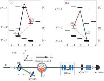
2. Experimental setupThe involved levels of 87Rb atoms and the experimental setup are shown in Figs. 1(a)–1(c), respectively, where |a〉 = |52S1/2,F = 1〉, |b〉 = |52S1/2,F = 2〉, and |e〉 = |52P1/2,F′ = 1〉. The right- and left-circularly polarized signal light fields ε±(z,t) are tuned to the transition |a〉 ↔ |e〉, respectively. The horizontally polarized controlling light field is composed of right- and left-circularly polarized components, which is tuned to the transition |b〉 ↔ |e〉. The atomic ensemble used for optical storage is a cigar-shaped cloud of cold 87Rb atoms which are provided by a two-dimensional (2D) magneto-optical trap (MOT). A pair of rectangular anti-Helmholtz coils with a size of 170 mm×65 mm is used to produce a magnetic field for the 2D MOT. The transverse gradient of the magnetic field is 15 Gs/cm (1 Gs = 10–4 T). The six trapping light beams have Gaussian profiles, whose diameters are all about 25 mm. The power of each trapping beam is about 20 mW. The size of the cold atomic cloud is about 4 mm×4 mm×7.5 mm.
The experimental setup is shown in Fig. 1(c). The signal and controlling light beams collinearly go through the cold atom cloud along the z direction, which can effectively suppress decoherence due to atomic motions.[30] Their powers (diameters) are ∼65 μW (1 mm) and ∼ 12 mW (4 mm), respectively. Owing to the optical pumping by the stronger controlling laser, the most atoms are prepared into the state |a〉. For further preparing the atoms into Zeeman sublevels |am=−1〉 or |am=1〉 with equal population (m is the magnetic quantum number), we use a π-polarized pumping laser beam P, which drives the transition |5S1/2,F = 1,m = 0〉 ↔ |52P3/2F′ = 0,m = 0〉 and propagates through the atoms along the x direction. Its power and diameter are ∼ 4 mW and ∼ 20 mm, respectively. The dephasing rate of the magnetic-field-sensitive (MFS) coherence is large,[31] which is one of main limits to the storage lifetime. In the present work, we use the scheme demonstrated in our previously published paper[32] to overcome this limit. As shown in Figs. 1(a) and 1(b), we use a moderate magnetic field (12 Gs) to lift the Zeeman degeneracy of the states |a〉 and |b〉, and then form two three-level Λ-type EIT systems, one is |am=−1〉 − |em=0〉 − |bm=1〉, which is coupled by the right-circularly polarized signal light fields ε+ and left-circularly polarized controlling component C−, and the other is |am=1〉 − |em=0〉 − |bm=−1〉, which is coupled by the left-circularly polarized signal field ε− and right-circularly polarized component of controlling field C+. The mapping between the signal light fields ε±(z,t) and the spin waves may be described by the two dark-state polaritons  [9,32]

respectively, where

is the Rabi frequency of the right-(left-) circularly polarized controlling components
C±,
Na is the total number of atoms,
g is the atom-field coupling constant,
S±(
z,
t) are the spin waves associated with the magnetic-field-insensitive (MFI) coherences |
am=−1〉 ↔ |
bm=1〉 and |
am=1〉 ↔ |
bm=−1〉, respectively, and are expressed as

with
ωab being the frequency of the transition |
a〉 ↔ |
b〉, and
Nz(≫ 1) being the number of atoms in an interval Δ
z. By adiabatically switching off the controlling light beam, cos
ϑ(
t) will be rotated from 0 to
π/2 and the input pulse of signal field
ε+(
z,
t) or
ε−(
z,
t) will be transferred into the MFI spin wave
S+(
z,
t) or
S−(
z,
t),respectively. However, if the controlling light beam is adiabatically switched on, cos
ϑ(
t) will be rotated from
π/2 to 0 and the pulses of signal field
ε+(
z,
t) or
ε−(
z,
t) will be retrieved from the spin waves
S+ and
S−, respectively. Such two processes correspond to the “writing” and “reading” processes respectively. Since the signal fields are only stored into the MFI spin waves, we can achieve a long-lived optical storage.
[25] The time-dependent retrieval efficiencies
η±(
t) for right- and left-circularly polarized signal light fields are defined as

respectively, where Δ
t =
t2 −
t1 is the storage time,
corresponds to the retrieved photon numbers of right- and left-circularly polarized signal light fields at time
t2, respectively, while

corresponds to the input photon numbers of right- and left-circularly polarized signal light fields at the initial time
t1, respectively.
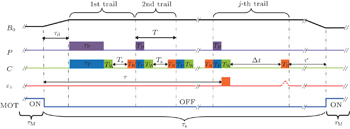
The time sequences for the atomic cooling and signal storage are shown in Fig. 2. Each experimental circle includes MOT-on and MOT-off processes, which are used for loading cold atoms into MOT and storing optical signals into the cold atoms, respectively. The loading atoms need a time interval of τM. After the loading, the MOT is switched off and the storage sequence starts. At the beginning of storage time sequence, the guiding magnetic field B0 ≈ 12 Gs is quickly applied. After a time delay of τd = 10 μs, the MOT magnetic field decays to zero and the guiding field becomes stable. In this case, we start the first optical storage trial. First, we let the pump laser P and linearly polarized controlling light beam C both work for τP = 5 μs to prepare the atoms into the desired state |amF = –1〉 or |amF= 1〉. After the preparation, the pump light is switched off and the controlling light is kept on for TW = 100 ns to perform the first writing operation. At the end of the writing operation window, the controlling light is switched off over 20 ns. After a time interval Ts = 200 ns, the controlling light is switched on again to read the stored signal. For the reading operation window TR = 100 ns. After the reading, the first storage trial is concluded and the second storage trial is started. In the beginning of the second storage trial, both pumping and controlling light beams are switched on for TP = 100 ns for atomic preparation, which is shorter than that of the first trial (τp = 5 μs). The following are the writing, waiting, and reading operation windows, which are the same as those in the first trial. The total period of the second trial is T = Tp + TW + Ts + TR = 500 ns. After the 2nd trial, the 3rd, the 4th, …, and the N-th trial are performed in order. Each one includes preparing, writing, waiting, and reading operations, which are the same as those in the second trial. If the signal pulse is emitted and directed into the cold atoms at the j-th trial, the storage sequence will be quickly stopped at this time. After a variable storage time Δt, we switch on the reading controlling beam to retrieve the stored signal. After a time delay τ′, we start the next experimental circle. The width of the signal pulse is 50 ns. For realizing effective storage, the falling edge of the signal pulse is overlapped with that of the controlling light pulse at j-th trial. The time delay between MOT off and the storage event can be written as

which depends on the trial
j. The period of the storage sequence in each circle can be written as

The repetition rate
F can be written as

From this relation, we can see that
F decreases with the increase of MOT-on (MOT-loading) period
τM when
τs is kept constant.
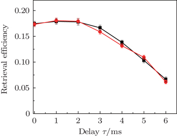
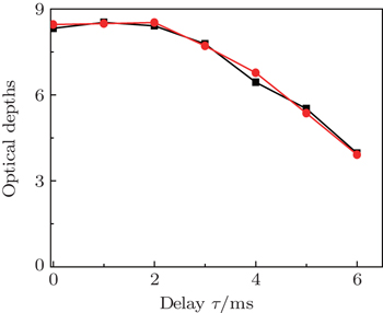
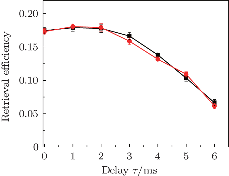
3. Results and discussionWe first measure the dependences of the retrieval efficiencies η± for a zero-storage time (Δt = 0.2 μs) on time delay τ, respectively. In the measurements, we keep τM = 91.5 ms and τs = 8.5 ms, so the repetition rate is calculated to be F = 10 Hz. The red-circle and black-square curves in Fig. 3 are the measured retrieval efficiencies for the right- and left-circularly polarized signal light fields each as a function of delay time τ, respectively. The measured results for right- and left-circularly polarized signal light fields are very close to each other and decrease with the increase of time delay τ. Within the delay range from 0.015 ms to 3.5 ms, the retrieval efficiency may exceed 15%. For understanding the decreases of the retrieval efficiencies with the increase of delay τ, we measure the optical depths of the right- and left-circularly polarized signal light fields as a function of the delay τ, respectively. The measured results are shown in Fig. 4, which decrease with the increase of delay τ; the reason for this is that the number of atoms drifting out of the signal–beam region increases with the increase of τ. Considering the dependences of the retrieval efficiencies on the optical depth,[26,33] we may understand the results in Fig. 3.
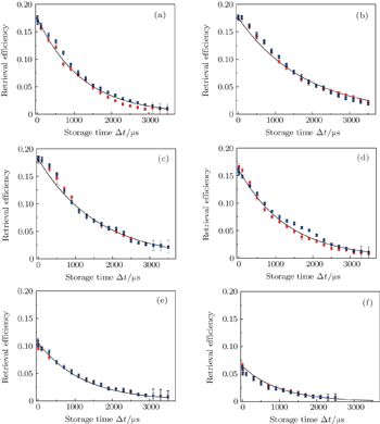
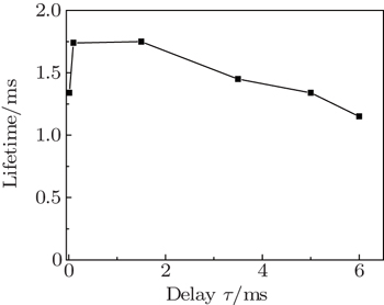
Next, we measure the dependences of retrieval efficiencies on the storage time Δt for several different values of delay τ. In the measurement, F is still kept at 10 Hz. The red circle and black square dots in Fig. 5(a)–5(f) are the measured retrieval efficiencies of right- and left-circularly polarized signal light fields for delays of 0.015 ms, 0.1 ms, 1.5 ms, 3.5 ms, 5 ms, and 6 ms, respectively. The solid lines in Figs. 5(a)–5(f) are the corresponding fittings to the measured data using η (Δt) = η0 e–Δt/τ. According to these fittings, we may obtain 1/e lifetimes for the different delays and then plot the dependence of the lifetime on the delay τ, which is shown in Fig. 6. From this figure, we can see that the maximum lifetime is about 1.7 ms, which occurs in the delay range from 0.1 ms to 1.5 ms. When the delay is beyond the range, the storage lifetime will reduce. The reason may be explained as follows. If the delay is very short (τ = 0.015 ms), the MOT magnetic field will not decay to zero within such a short delay. In this case, the remaining magnetic field will cause significant inhomogeneous Zeeman broadening of the spin waves,[13] which will lead to a reduction of the storage lifetime. On the other hand, if the delay τ is very long, the temperature of the cold atoms will acquire a significant increase, which leads to the decrease of storage lifetime with the delay.
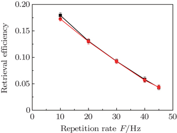
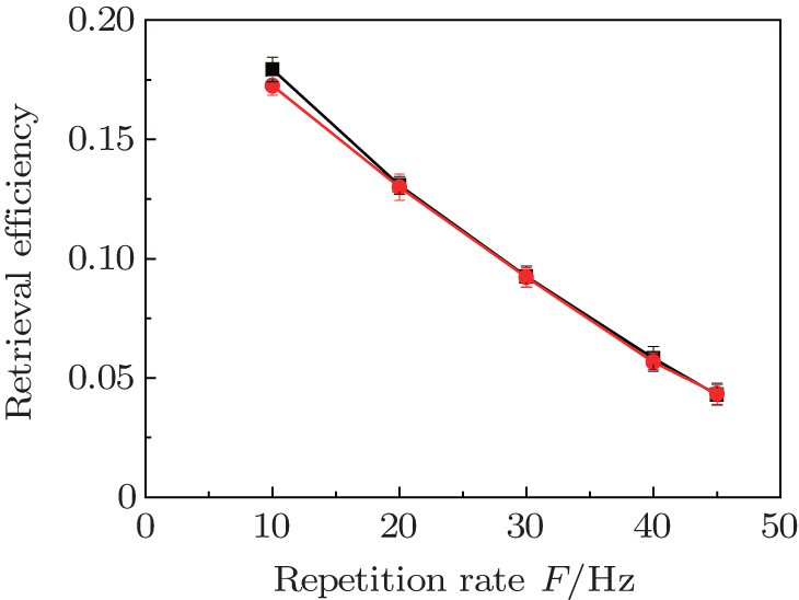
We then measure the dependences of retrieval efficiencies on repetition rate F. In the measurement, the period of storage sequence is kept at τs = 8.5 ms and the repetition rate F is changed by varying the MOT-on period τM. The storage of the right- or left-circularly polarized signal light fields are performed in the first trial, and their retrieval efficiencies are measured for the storage time Δt = 0.2 μs, respectively. The red circle and black square dots in Fig. 7 are the measured results, which show that the retrieval efficiencies decrease with the increase of F. These results can be easily explained as follows. The number of trapped atoms can be written as[34]

where
τc is the lifetime of the trap,
nss ∝
d2 is steady-state number of trapped atoms,
d is the diameter of the cooling laser beam. Since the optical depth (OD) is proportional to the number of trapped atoms
n(
τM), it can be written as

where
Od0 ∝
nss ∝
d2. From this relation, we can see that OD decreases with the decrease of MOT-on period
τM, which makes the retrieval efficiencies decrease with the increase of repetition rate
F. If one hopes to improve the retrieval efficiencies in the case of high
F, they need to increase OD by expanding the diameters of the trapping laser beams.
4. ConclusionsWe study the optical storage of right- and left-circularly polarized signal light fields in a cloud of cold atoms trapped in a MOT. The retrieval efficiencies of right- and left-circularly polarized signal light fields each as a function of storage time are measured for different time delays between MOT off and the storage event, respectively. The measured results show that the retrieval efficiencies decrease with the increase of delay τ. In the delay times ranging from 0.015 ms to 3.5 ms, the storage lifetime and the retrieval efficiency for a zero-storage time (0.2 μs) can exceed 1.4 ms and 15%, respectively. The measured retrieval efficiencies of right- and left-circularly polarized signal light fields are close to each other, the present storage system can be used to store polarized photonic qubits. The dependence of the retrieval efficiency for the zero-storage time (0.2 μs) on repetition rate F is also measured. The further improvement of the retrieval efficiencies in the case of high repetition rate F requires one to expand the diameters of the trapping laser beams. The present results will provide important help for optimizing the storage of the polarized entanglement photons.


 ]
]