1. IntroductionHigh-order harmonic generation (HHG) from the non-perturbative nonlinear interaction between intense femtosecond laser pulses and atoms or molecules has been proven to be a reliable coherent source in extreme ultraviolet (XUV) and soft x-ray spectral regions.[1,2] HHG driven by monochromatic or bichromatic laser in a collinear geometry has been extensively studied both experimentally[3–6] and theoretically[7–11] in the past years, the non-collinear HHG has received less attention, owing to its complex geometry. Nevertheless, the non-collinear geometry provides a natural way of separating the high harmonics from the fundamental beam, especially for the high harmonic radiation output coupling in an enhancement cavity of XUV frequency comb.[12,13] It is also beneficial to better phase matching in HHG.[14] The HHG process may be well described by the simple three-step model:[15] an valence electron is firstly tunnel-ionized out of an atom in the strong laser field into the continuum state, then is accelerated and brought back to the atom by the laser field, finally recombines with the parent nuclei to emit a high energy photon. Quantum paths of the electrons are usually categorized by the excursion time in the continuum state, the shortest two of which are the well-known short and long trajectories. In a two-color scheme, HHG may be understood as high-order sum and difference frequency mixing.[16] For instance, when the fundamental frequency ω1 and the weak second harmonic ω2 a beam are mixed, a harmonic photon ω is produced by absorbing (positive number) or emitting (negative number) q1 photons with ω1 and q2 photons with ω2. This gives another way of determining the quantum paths which are characterized by the photon number (q1, q2). A combination of q1 photons and q2 photons, which obeys the transition selection rules contributes to the HHG spectrum.[5] All the contributions from different photon numbers (q1, q2) of the same frequency ω overlap spatially in the collinear two-color scheme, thus the individual quantum path is undistinguishable. The two-color HHG has been extended to non-collinear geometry by two[17] and even multiple laser beams.[18] Spatially discrete harmonics have been observed in non-collinear two-color HHG spectra which are explained in terms of the conservations of energy, momentum, and parity. Different paths (q1, q2) with the same harmonic frequency ω correspond to different propagation angles because of the momentum conservation, making it possible to separate individual quantum path in the space domain. The spatial separation of non-collinear HHG has been proposed to isolate single attosecond pulse[19] and study the orbital angular momentum transferring from fundamental to HHG.[20] Recently the phase matching effect and interference between adjacent paths in non-collinear HHG have been investigated[21] as a frequency-domain analogy to the early work concerning the quantum path interferences for trajectories with different excursion times.[22–24] The interference is explained by the dipole phase difference among harmonics from different source positions.
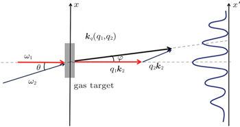
In the present paper, we numerically simulate the non-collinear HHG to provide a clear understanding of the quantum path interference. The frequency dependence of this interference is identified, which is attributed to the spatially dependent dispersion of the dipole phase of the atom. In our simulation the single atom response is calculated by solving time dependent Schrodinger equation (TDSE) in strong field approximation (SFA)[25] with which a quantum analysis of the classical three step model is performed. In the SFA, the excited states and Coulomb field are not taken into account. The propagation effect in the gas target is ignored and only a single slice is considered as the HHG source in the calculation, which is infinitely thin in the propagation dimension and includes the beam profile in the lateral dimension. The far-field HHG spectra at a distance of 100 cm are calculated by the Huygens’ integral of the near-field distribution in Fresnel approximation.[26] The driving field is composed of two Gaussian beams with frequencies ω1 and ω2 crossing with a small angle θ at the focus of both beams. A schematic of the simulation geometry is given in Fig. 1.
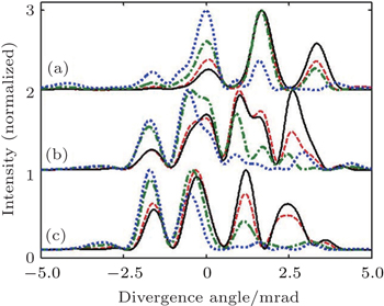
2. Numerical resultsThe simulation result for a strong fundamental field ω1 (2 × 10¹⁴ W/cm2, 800-nm wavelength) and a weak second harmonic ω2 (0.2 × 10¹⁴ W/cm2, 400-nm wavelength) with a crossing angle θ = 8.7 mrad is shown in Fig. 2(a). The pulse duration is 30 fs and the beam waist is 50 μm for both beams.
Only a single slice of neon atoms placed at the focus was considered. The weak field ω2 gives rise to even order harmonics as well as the off-axis discrete harmonics as shown in the spectra. The position of each discrete harmonic is determined by the conservation rules,[17]
where
N ∈
Z.
The propagation angle φ = θ q2ω2/ω predicted by the conservation rules is fitted well with our simulated spectra for orders lower than 25. The non-collinear HHG spectrum presents a spatial mapping of quantum paths determined by the photon absorption (emission) numbers (q1, q2). It is possible to distinguish different (q1, q2) paths for a certain harmonic frequency ω by their unique propagation angle φ.
The angular gap of neighboring quantum paths Δφ = 2θ ω2/ω is inversely proportional to the harmonic frequency ω. On the other hand the divergence of the discrete harmonic increases with frequency increasing.[27] This makes the angular gap of discrete harmonics relatively large for low orders, and ensures the contribution of each quantum path to be resolvable in harmonic spectrum at far field. When the gap is comparable to or even smaller than the divergence of the discrete harmonics, the interference of adjacent paths appears. In Fig. 2(a) a significant deviation from the predicted propagation angle appears in high orders because the interference becomes more distinct for paths in higher orders due to their smaller spacings. The variations of far-field distribution as a function of the delay between two driving pulses for the 21st, 25th, and 29th order are shown in Figs. 2(b)–2(d). The position of main peaks in low harmonic orders do not change with delay, while an overall shift of the peaks with delay is observed in high orders(> 25).[21] The adjacent quantum interference is modulated by the relative phase between the two driving pulses. There is a transition around 25th order revealing a mixed pattern of Figs. 2(b) and 2(d) where the shift is observed between the remaining main peaks as shown in Fig. 2(c). This pattern is formed due to the insufficient overlap in the intermediate harmonic orders. In the two-color HHG, the far-field divergence of a discrete emission from a particular path is expected to vary with the delay between the two-color fields.[28] Therefore a different delay corresponds to a different overlap between adjacent paths. This effect is especially important for the intermediate orders because of their insufficient overlap. The adjacent paths from intermediate orders change between independence and overlap according to their divergence varying with delay. Thus the harmonic emission reveals an intermediate pattern between discrete and interference, as shown in Fig. 2(c).
3. DiscussionThe interference between adjacent quantum paths may be understood in a framework of frequency chirp induced by the intensity-dependent dipole phase.[29,30] The dipole phase is given by  [31,32] where j refers to short (j = 1) or long (j = 2) trajectory contributing to the q-th harmonics, I(z,r,t) is the intensity envelope of the driving laser pulse ω1, αj depends on the electron excursion time in the continuum and its values for short and long trajectories are quite different. The discussion in this work is restricted to short trajectories which dominates the harmonic emission at the parameters used in Fig. 2(a), unless otherwise mentioned. The short trajectory is selected by the electron excursion time at a single atom response level. The intensity dependence of the dipole phase results in a curvature of the harmonic wave front, which is equivalent to a spatial frequency chirp Δf(x) = − ∂Φ (x)/∂x induced by the dipole phase. The divergence of the harmonic in the far-field is broadened by this curvature. Under the assumption of a Gaussian beam
  the far-field propagation angle of the q-th harmonic as a function of near-field radial axis x may be expressed as[30]
where

The first term on the right-hand in Eq. (
2) originates from the momentum conservation. The second term deriving from the spatial chirp which broadens the far-field divergence for each quantum path (
q1,
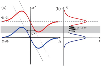
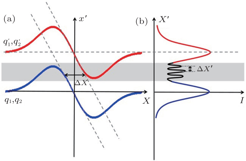
q2). The explanation of the interference is illustrated in Fig.
3, which shows the mapping from the near-field to the far-field calculated from Eq. (
2). For an individual quantum path (
q1,
q2), almost one-to-one relationship is found from the near-field
x to the far-field
x′ because of the dipole phase-induced curvature of harmonic wave front. The positive chirp component of (
q1,
q2) path and negative chirp component of the adjacent

path are overlapped in the shaded area in Fig.
3 where the interference takes place. The two interference components are separated by a distance of Δ
x on the opposite edge in the near-field. The separation Δ
x gives rise to the interference pattern of adjacent paths of
q-th harmonic, which may be written into the following expression:
[29]
where
x′ is the far-field radial axis,
Sq the far-field distribution of
q-th harmonics along
x′,
L the distance between near- and far-field,
Φq1,q2(
x′) the phase that is a slow varying function of quantum path (
q1,
q2) adopted from the phase of the two driving pulses.
The interference fringe interval Δx′ is mainly determined by Δx. Since the HHG distribution usually concentrates in the central part of the laser beam where the chirp is almost linear, an approximation of Δx from the calculation of Eq. (2) may be written as
which indicates that the fringe relates to the crossing angle, beam waist and dipole phase. From Eq. (
4) we may easily deduce that a larger beam waist or crossing angle will lead to a larger near-field separation Δ
x and correspond to a smaller far-field fringe interval. When the fringe interval is comparable to the interval between adjacent paths, the interference pattern shows a notable overall shift for each of the main peaks (see Fig.
2(d)). Adjusting the parameters to support a smaller interval, we observe well resolved interference fringes between unshifted main peaks (see Fig.
4(a)). The well resolved fringes contain achievable phase information about the adjacent paths, but they are more difficult to observe experimentally because of the weaker intensity than those of the main peaks.
The effect of the dipole phase is not so straight forward. At certain intensity I0, the coefficient α varies with harmonic order. A plot of α calculated by a saddle point analysis[33] as a function of harmonic order for short trajectories in the mixed laser field ω1 and ω2 is shown in Fig. 4(b). The value of α increases monotonically with harmonic order because α is positively correlated to the excursion time that electrons spend in the continuum state. Larger harmonic order corresponds to a longer excursion time for short trajectories for a certain laser intensity. The increasing of α with harmonic order is partly responsible for the more obvious interference in high orders than that in low orders[21] as shown in Figs. 2(b)–2(d) because larger α implies a larger divergence of individual discrete harmonic and the better overlapping of neighboring paths. The interference provides a way of retrieving α through Eqs. (3) and (4):
In order to improve the accuracy of the retrieval, larger beam waist 100 μm and crossing angle 17.5 mrad are chosen to acquire fine interference fringes as shown in Fig. 4(a). The values of coefficient α calculated for several orders from the fringes in Fig. 4(a) are denoted by dots in Fig. 4(b), which are on the same order of magnitudes as the theoretical value with an overestimate. The result shows that the simple physical picture given in Fig. 3 is suitable for describing the interference between adjacent quantum paths in the non-collinear HHG scheme qualitatively. An accurate theoretical model is required to provide more precise analysis of the interference process. The interference is also affected by driving laser intensity. For high orders at higher intensity, the spacing between different paths is smaller while the dipole phase is larger, which leads to a larger divergence of individual path. Thus the interference pattern for high orders at high intensity is more or less similar to the long trajectory at low intensity which has weaker main peaks and stronger interference. Besides the near-field separation Δx, the interference also depends on the phase difference  The Φq1,q2 (x′) is determined by the phase between the two driving pulses. For adjacent quantum paths (q1, q2) and (q1 – 4, q2 + 2) when ω2 = 2ω1, it may be written as

where
ϕq1,q2 (
x′) is adopted from the geometrical phase between the two driving beams,
ψ1 and
ψ2 denote the CEPs of the two pulses respectively, Δ
t is the time delay between the two pulses, and Δ
Φq has little effect on the interval of the interference fringe since
ϕq1,q2 (
x′) only has a weak dependence on
x′. But a variation of CEP and time delay between the two pulses determine a shift of the interference fringe. The variation periods are
π/2 for
ψ1,
π for
ψ2 and 0.67 fs for delay respectively, the last of which is consistent with the result presented in Figs.
2(c) and
2(d). The strong dependence on CEP and delay implies that stabilized CEP and relative timing of the driving pulses are necessary for observing the interference for the higher order harmonics in experiment, otherwise the interference will be smeared by the averaging effect of the driving laser jitter. The single shot experimental spectrum in Ref. [
21] implies a CEP jitter which is prevented to obtain a well-matched spectrum to the simulation.
The discussion above is also valid for long trajectory that has larger coefficient α and therefore more complicated interference pattern. Since short and long trajectories may be separated experimentally by phase matching[34] or spatial filtering[35] and theoretically by selecting the electron excursion time, it is reasonable to restrict the discussion to short trajectory for simplification.
To know the validity of our single slice gas target calculation, We calculate the spectra by a non-adiabatic two-dimensional propagation model modified in Ref. [36] as macroscopic effect plays an important role in HHG.[37] In the case of non-collinear beams, radial asymmetry assumed in Ref. [36] is not available. Therefore the two-dimensional grid, which is in the plane formed by wave vector k1 and k2, is used instead of the three-dimensional grid (see supplementary information of Ref. [38]). The interaction region is 1 mm–3 mm long and centered at the beam focus. The gas pressure in the interaction region is 40 Torr (1 Torr=1.33322 × 10² Pa). Other parameters are the same as those in Fig. 2(a). The result in 1-mm gas target given in Fig. 5 is similar to the single slice result shown in Fig. 2(a) except for some small differences in the relative intensity among different quantum paths.
The discrete structure for low orders and the interference pattern for high orders survive after the 1-mm-long propagation in the gas medium. In 2-mm or longer gas target, the dominating peaks move towards the difference-frequency side (q2 < 0). This shift may be explained by the additional geometrical phase mismatch term induced by the non-collinear geometry.[21] The sign of additional mismatch term Δk< = q2θ (2q2/q − 1)ω/ckq is always opposite to q2, i.e., Δk< is negative for sum-frequency HHG (q2 > 0) and it is positive for difference-frequency HHG (q2 < 0). The negative neutral atom dispersion plays an important role in a long gas medium with moderate power,[35] and such a dispersion may be compensated for by additional Δk< in difference-frequency HHG. Therefore the difference-frequency HHG is more likely to add in a long medium, leading to the shift of the dominating peaks. The result verifies the validity of ignoring the macroscopic effect in order to achieve a brief and clear physical understanding, but only valid for short medium. Information from the single atom response is not destroyed by the macroscopic effect in a gas target as short as 1 mm.[39]


 , Teng Hao, Ye Peng, Wang Li-Feng, He Peng, Wei Zhi-Yi‡,