Heo Jino 1, 2, Hong Chang-Ho 1, 2, Lee Dong-Hoon 1, 2, Yang Hyung-Jin 1, 3, †,  |
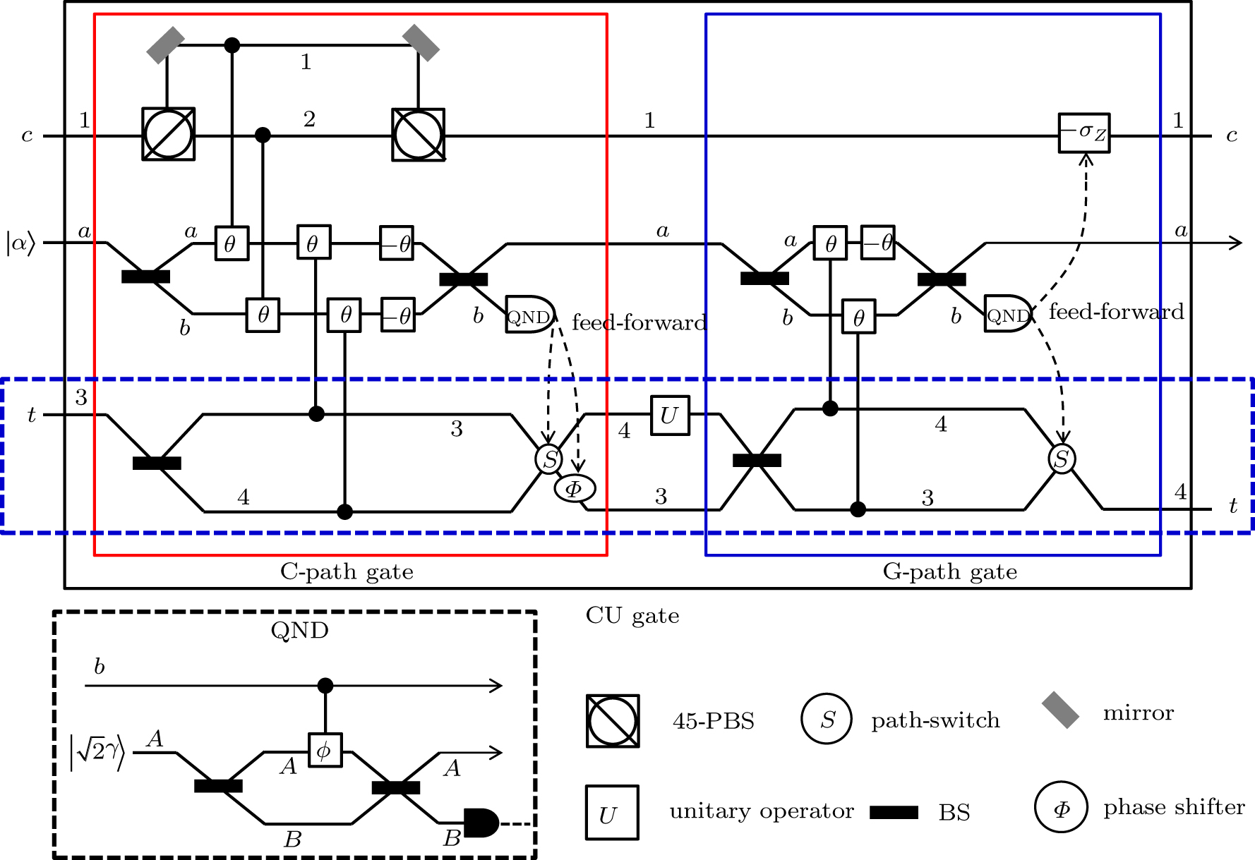
Schematic diagram of CU gate (black box), which is comprised of the consecutive operation of a C-path gate (red box on the left)[34,35] and a G-path gate (blue box on the right) using XKNLs, the qubus beams, the QND (PNR) measurements (dotted line black box), and feed-forwards. The CU gate is composed of three parts: the C-path gate, the operator U, and the G-path gate. First, in the C-path gate, the two photons c and t (dotted line blue box) in the input state (signal) induce controlled phase shifts θ in the two qubus beams (probe) by the XKNLs interaction. Then, the linear phase shifters −θ are operated on the two qubus beams. Subsequently, we measure the probe beam on the path b via the QND (PNR) measurement,[33–38] which can precisely discriminate the number of photons |n〉b in the probe beam on the path b. According to the measurement outcome |n〉b of the QND (PNR) measurement, we determine whether to operate the phase shifter Φ and the path-switch S on the target photon t by feed-forward. After passing the C-path gate, the target photon path is split according to the control photon polarization. The target photon goes through path 3 (or 4) when the control photon is |R〉 (or |L〉). In the second step, the unitary operator U on path 4 is applied to the target photon. In the third step of the G-path gate, the XKNLs induce phase shifts θ according to the target photon t, and then the linear phase shifter −θ is performed on the qubus beam on path a. For gathering the target photon on the split path, we finally apply the unitary operator −σZ to the control photon, and the path-switch S to the target photon via the feed-forward, depending on the measurement outcome |n〉b of the QND (PNR) measurement. Consequently, the CU gate performs a controlled-unitary (CU) operation on the input state. |