

Scientific and technological challenges toward application of lithium–sulfur batteries
[Yin Ya-Xia 1 , Yao Hu-Rong 1, 2 , Guo Yu-Guo 1, 2, 3, †,  ]
]
]
|
|


† Corresponding author. E-mail:
Project supported by the Ministry of Science and Technology (Grant Nos. 2012CB932900 and 2013AA050903), the National Natural Science Foundation of China (Grant Nos. 51225204 and U1301244), and the “Strategic Priority Research Program” of the Chinese Academy of Sciences (Grant No. XDA09010300).
Recent progress in improving Li–S batteries’ cathodes, anodes, and electrolytes via different approaches is summarized. The poor conductivity of sulfur cathodes, the dissolution of polysulfide intermediates, and the high reactivity of metal Li anodes currently motivate a great deal of research. Urgent challenges concerning Li anodes are also emphasized.
With the emerging demand to increase the energy density of battery systems for electrically powered vehicles and large scale electricity storage, conventional lithium-ion batteries based on intercalation-type electrodes have almost reached their energy storage limit. Li–S cells, characterized by an electrochemical process with two-electron transfer per sulfur molecule,

Despite the outstanding advantages of the Li–S battery system, the realization of practical Li–S batteries is hampered with severe issues: poor electrical conductivity of sulfur and its reduced counterpart (Li 2 S 2 or Li 2 S), fast capacity loss from the soluble polysulfide intermediates formed in the redox process of S 8 , and very intense reactions of Li anodes with electrolytes and polysulfides. The development of sulfur cathode materials has been picked up since Nazar successfully impregnated sulfur into a mesoporous carbon substrate in 2009. [ 4 ] Intensive efforts have also been exerted on electrolytes and Li anodes to make the Li–S battery system a feasible, safe and efficient technology.
Herein we start from the basic scientific issues underlying the Li–S battery system and discuss problems inherent in today’s sulfur cathodes, lithium anodes, and electrolytes. The recent progress with Li–S batteries is summarized. Urgent challenges are detailed in order to provide insight into the imminent developments of the Li–S battery system.
Sulfur has more than 30 known solid allotropes in the forms of rings and unbranched chains. [ 5 ] Under standard temperature and pressure it is thermodynamically stable as ringlike octasulfur (cyclo-S 8 ), and therefore the electrochemical reaction mechanisms of cyclo-S 8 have been widely investigated.
During the discharge process (Fig.
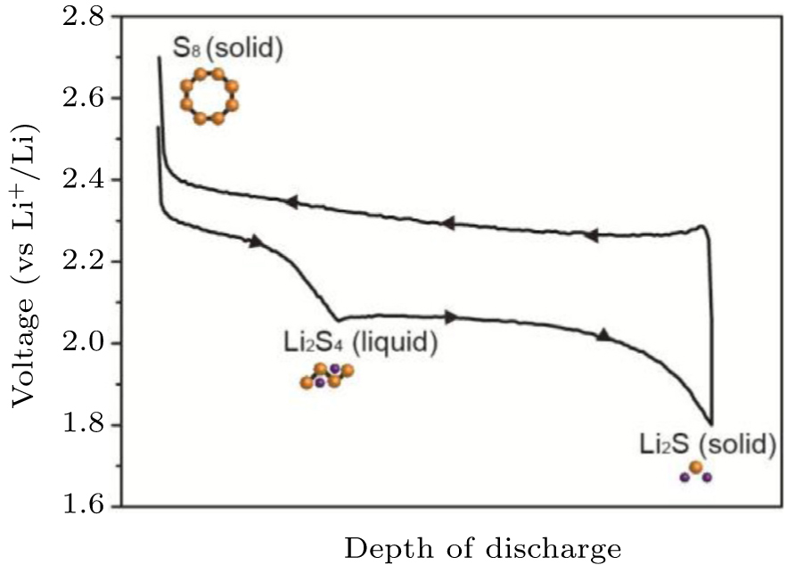 | Fig. 1. Typical discharge–charge profile of a Li–S cell with cyclo-S 8 cathode. |
The complex multistep reaction of Li with S produces different intermediate species. Among them, the soluble polysulfide intermediates (mainly Li 2 S 4 –Li 2 S 8 ) are notorious with their severe redox ‘shuttle’ between the sulfur cathode and Li anode. That is, these soluble polysulfide intermediates (Li 2 S n ) with relatively high mobility will diffuse to the Li anode through the separator and be electrochemically and chemically reduced into soluble polysulfide species (Li 2 S n −1 ), or even into insoluble Li 2 S 2 or Li 2 S deposited on a Li anode. Resultant soluble polysulfide species (Li 2 S n −1 ) can diffuse back to the sulfur electrode, and are re-oxidized to create higher forms of polysulfide (Li 2 S n ) again. The above process takes place repeatedly during the operation of the Li–S cell and diminishes battery performance by progressively consuming active sulfur species, corroding the Li anode, and polarizing the Li anode. [ 2 ] The strong redox shuttle can be clearly observed in the cell’s charging voltage, such that a typical Li–S cell cannot be charged above 2.5 V, and meanwhile elemental sulfur cannot be formed. [ 15 ]
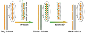
Besides cyclo-S 8 , some other sulfur allotropes appear under carefully selected conditions, due to intra/intermolecular rearrangement, albeit most allotropes are unstable or metastable under normal conditions. Very little is known about the character and behavior of these other sulfur allotropes. [ 5 , 16 ] Guo et al. investigated the electrochemical behavior of one-dimensional S chains in Li–S batteries by encapsulating S chains in carbon nanotubes (Fig.
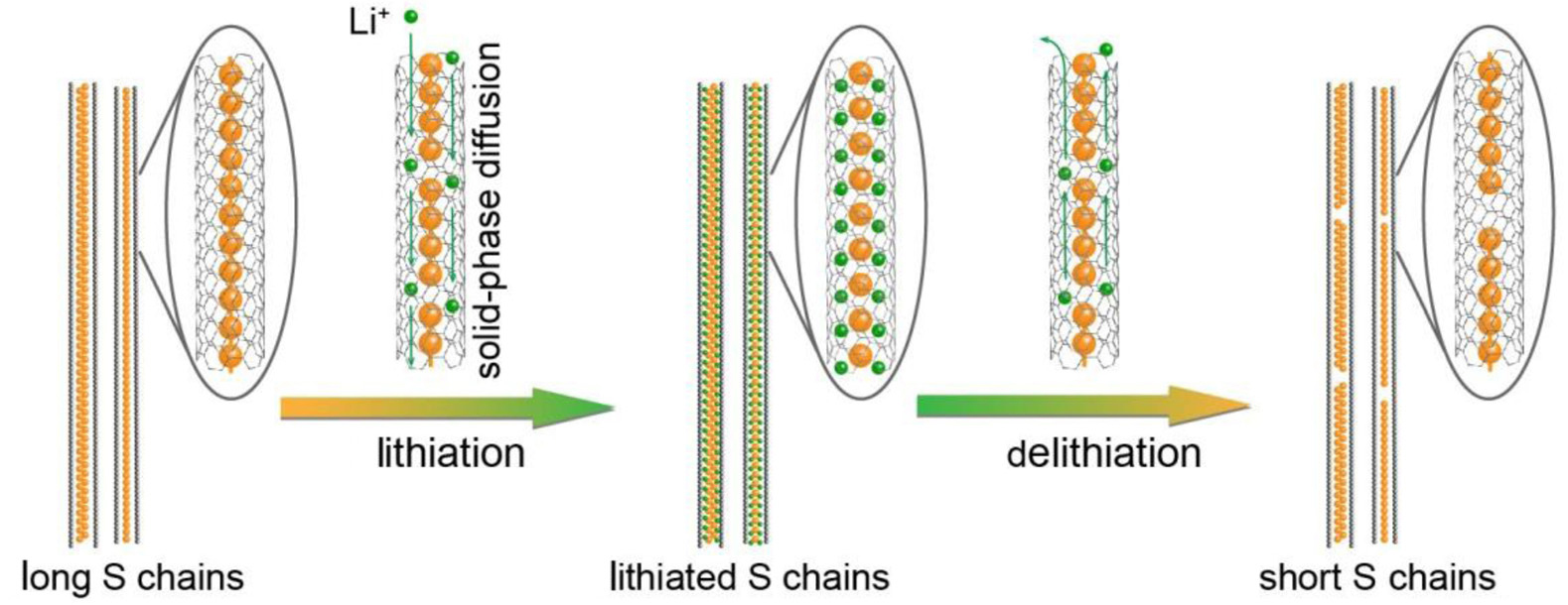 | Fig. 2. Schematic of electrochemical lithiation/delithiation processes of S chains in a Li–S cell. [ 17 ] |
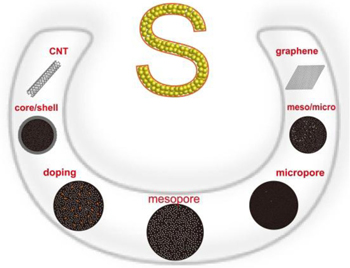
To offset a number of issues, i.e., poor electrical conductivity of sulfur and its reduced counterpart (Li 2 S 2 or Li 2 S), volume changes during the discharge/charge process, and fast capacity loss in the soluble polysulfides, growing proliferation of robust architectures and novel fabrication methods have been intensively investigated by combining sulfur with other materials, including carbons, polymers, and inorganic materials. Suitable materials combined with sulfur could possess good conductivity to improve the electrical conductivity of sulfur used alone, and/or have a strong interaction with sulfur or polysulfides effectively confined on the cathode side. A matrix of polymer (especially a conductive polymer) and inorganic material (e.g., an oxide) can improve the electrochemical performance of sulfur to a certain degree. However, intrinsic drawbacks, such as the swelling of the polymer in an organic electrolyte during a prolonged cycle or extreme polarization due to the poor conductivity of oxides could limit their practical application in sulfur cathodes. Distinctly different from polymer and inorganic matrix, carbons have great advantages to host sulfur owing to their diversity, abundance, low cost, elasticity, superior conductivity and good affinity with sulfur. [ 18 ] Therefore, diverse carbon materials with different morphologies (Fig.
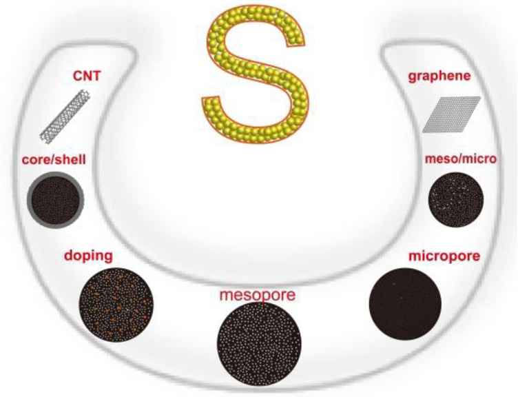 | Fig. 3. Diverse carbon substrates to host sulfur. |
Various strategies have been widely utilized to modify or construct three-dimensional nanoporous carbon to obtain good conductivity (e.g., doped with heteroatoms, N or B) [ 27 , 30 ] and large pore volume to host sulfur (e.g., hierarchical micro/ mesoporous structure), [ 25 , 26 ] as well as the capability to suppress the diffusion of soluble polysulfides from sulfur cathodes (e.g., mesoporous core/microporous shell structure). [ 28 ] Precisely controlling the pore size of carbon materials can significantly influence the electrochemical properties of Li–S batteries. Considering the main capacity loss of the Li–S capacity originating from the formation of soluble polysulfide intermediates (Li 2 S n , n = 4–8), Guo et al. prepared microporous carbon substrate (carbon nanotube coated by microporous carbon, abbreviated as CNT@MPC) with the critical pore size (e.g., 0.5 nm) to host sulfur, where only chain-like S molecules (S 2−4 ) can be stored, and the cyclo-S 8 (∼ 0.7 nm) cannot exist in this small pore size. [ 17 ] The confined S 2−4 molecules can avoid the unfavorable transition between cyclo-S 8 and 
We have overcome the issues inherent in sulfur cathodes, because carbon materials offer high sulfur loading, high sulfur utilization, and cycle stability, so the practical implementation of Li–S batteries seems likely soon. However, severe cell swelling, depletion of lithium and electrolyte components, thermal instability and limited cycle life (30–60 cycle life at an 80% depth of discharge) were all observed in Li–S pouch cells. [ 31 ] All these issues originate from the fact that metal Li is highly reactive with commonly used liquid electrolytes and with the soluble polysulfide intermediates generated in the redox process of Li–S batteries. [ 32 – 36 ] So it is important to know precisely what happens in the Li–S battery system and explore correct strategies to guarantee judicious optimization of lithium electrodes for practical Li–S battery systems.
The Fermi energy of Li is higher than the low unoccupied molecular orbital of the commonly used liquid aprotic electrolyte solvents. Lithium thereby spontaneously reacts with them to form more thermodynamically stable products. The as-formed products deposit on the surface of a lithium anode, forming an ion-conductive (allowing Li + transport under an electrical field) but an electronically insulating layer (offering the active Li metal with corrosion protection), as exemplified in the solid electrolyte interphase model (abbreviated as SEI). [ 37 – 40 ] The resultant SEI layer imparts kinetic stability to the electrolyte, preventing further reduction, and thereby passivates high reactivity of the lithium, making it stable in electrolyte solvents. Since the Li electrode is always covered by the SEI layer in an aprotic electrolyte solution, the character of the SEI layer (e.g., chemical composition, thickness, morphology, and compactness) will govern the electrochemical behavior of Li anodes. The SEI layer has a mosaic-type, multilayered structure. [ 34 , 41 – 44 ] Multilayer surface films are comprised mostly of Li salts. Close to the Li surface, the components of the surface films contain mainly inorganic species of low oxidation states such as Li 2 O, Li 3 N, Li X ( X = F, Cl). [ 41 ] The outer surface of the films is comprised of organic species of higher oxidation states such as ROCOLi, ROLi, and RCOOLi. [ 45 ] These inorganic and organic species all are Li + ion conductors. Electrochemical Li dissolution and deposition can occur through such a surface film when an electrical field is applied to the Li electrode. The heterogeneous chemical structure [ 34 ] induces non-uniform current distribution along the Li electrode’s surface films, resulting in uneven Li deposition (rough lithium surface morphology). Upon the deposition of Li, needle-like or particulate Li is accumulated on the Li electrode, beneath the SEI film. Particulate Li forms with a lot of growth points, whereas Li might otherwise be deposited vertically and grow upward in dendrites with few growth points. [ 32 ] It should be emphasized that particulate Li could be reversibly stripped while many Li dendrites remain. The SEI films comprised of ionic species are significantly stiff and cannot accommodate the morphological change of the Li surface. [ 40 ] Large stresses build up in the Li electrode, which results in cracking of the SEI films and the formation of Li dendrites. Subsequently, pure Li is again exposed to the electrolyte and fresh SEI is formed on the cracked faces, leading to further loss of capacity. The formation of Li dendrites renders the poor cycle life and safety issue of Li electrodes in the following way. [ 32 , 40 , 45 , 46 ]
It is of particular interest that there is no serious dendrite growth in Li–S batteries, since the dissolved polysulfide (Li 2 S 8 -Li 2 S 4 ) intermediates are highly reactive and react with Li dendrites. [ 31 ] The chemical composition and structural configuration of the SEI layer becomes more complicated in the presence of soluble polysulfides than in conventional Li-ion batteries. [ 47 ] Soluble polysulfides diffused from a sulfur cathode can react with lithium continuously, progressively making the surface of lithium rough. [ 15 ] This rough surface morphology will accelerate the unacceptable reaction between lithium and electrolyte solvents, due to the higher relative surface area of the lithium. Re-formed SEI resumes in consuming more electrolyte, leading to swelling and to lithium/electrolyte depletion during prolonged cycling. It is worth mentioning that the Li dendrite problem should be considered again where no soluble polysulfides appear during the operation of the Li–S battery system.
To avoid the reaction of the soluble polysulfides with the Li anode, physical barriers with various specific functionalities have been used to retain polysulfide in the sulfur cathode side. Conductive carbon papers placed between the sulfur cathode and the separator, [ 48 ] a cabon layer coated on the separator, [ 23 , 49 ] and an ion selective membrane [ 50 ] have been used, respectively, to physically absorb or attract soluble polysulfides electrostatically. Liu et al. constructed a hybrid anode for a Li–S battery, in which a compacted graphite film is electrically connected with Li foil in parallel (Fig.
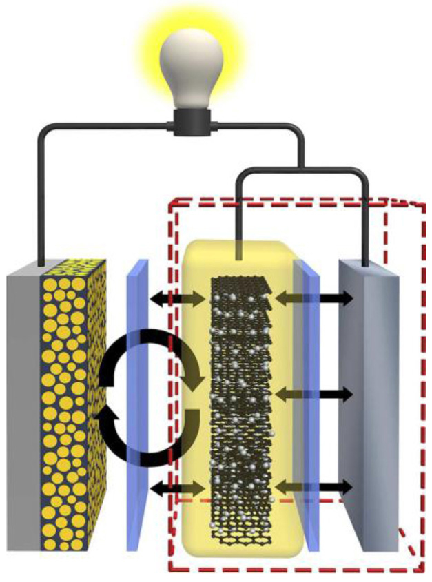 | Fig. 4. Schematic of hybrid anode to modulate surface reactions in Li–S batteries. [ 51 ] |
Besides the introduction of the blocker to keep polysulfides away from the Li anode, modifying the Li surface to form a stable SEI layer can effectively protect the Li anode from the attacks of both soluble polysulfides and electroylte. For example, coating the Li anode with flexible and Li + - permeable film (e.g., solid polymer electrolytes) can accommodate non-uniform Li deposition and allow Li + transport during cycles. [ 52 ] Apart from organic lithium ionic conductors, their inorganic counterparts with high Young’s modulus (such as Li 3 PO 4 ) [ 53 ] could be highly desired to coat on the surface of Li anode, which can restrain the Li dendrite growth and reduce the unfavorable reaction of Li metal with electrolyte. Alternatively, depositing sulfur powder on a Li anode can generate a native SEI layer on the Li surface by the reduction of S during contact with the electrolyte, which prevents generation of insoluble Li 2 S at the Li surface during cycling. [ 54 ] In addition, the current collector could play an important role on the Li anode because the current collector determines the nucleation at the initial Li-plating and consequently effects the morphology of Li-plating. In marked contrast to the conventionally used planar collectors, the growth of Li dendrites is effectively suppressed by the use of a three-dimensional current collector with a submicron skeleton for Li anode. [ 55 ]
To avoid these serious challenges inherent in metal Li anodes, metal Li-free anodes are widely considered. Lithium alloy (e.g., Li–Si, Li–Al alloy) materials are promising candidates to replace metal Li, owing to their higher capacity and relatively low plateau of Li insertion/de-insertion. [ 56 ] However, most Li alloys deliver poor cycling performance because of a huge volume change (e.g., 300% for Li–Si alloy) and unstable SEI layer during the repeated alloying/de-alloying reactions with Li. So a Li alloy with stable cyclic performance is a prerequisite for Li–S batteries. Yang et al. substituted Li–B alloy for metal Li. Abundant free Li is embedded in the electrochemical inert Li 7 B 6 three-dimension framework. [ 57 ] The inactive Li 7 B 6 framework can be stable for stripping/depositing Li, avoiding the common issues faced with alloy bulk materials (deformation, volume expansion or collapse) during repeated cycles. Lithium-boron anodes’ good electrochemical conductivity (1.43× 10 3 Ω −1 ·cm −1 ) and a high Li + ion diffusion rate, combined with the 3D configuration, ensure the uniform distribution of current density and a large variety of Li deposition sites within the Li 7 B 6 alloy. These features eliminate oriented crystallization of free lithium, reduce effective current density and promote the formation of the SEI layer. [ 57 ] Note that these Li–S batteries with a Li alloy anode could completely avoid the issues arising from traditional Li anodes with the compromise of reduced energy density, due to a lower voltage output than conventional Li–S batteries.
Liquid carbonate electrolytes, widely used in lithiumion batteries, have proven to be inappropriate for elemental sulfur cathodes since sulfur reduction intermediates chemically react with carbonate-based solvents [e.g., ethylene carbonate (EC), propylene carbonate (PC), and diethyl carbonate (DEC)]. [ 58 ] Thus most elemental sulfur cathodes cannot work in carbonate electrolytes. However, ether-based electrolytes, e.g., 1,3-dioxolane (DOL), 1,2-dimethoxyethane (DME), and tetra-(ethylene glycol) dimethyl ether (TEGDME) have high polysulfides solubility and result in more complete reduction of soluble polysulfides. In particular, the mixed solvent system of DOL and DME appears to be more practical for rechargeable Li–S systems, because it achieves a good balance among three factors: sulfur utilization, rate capability, and lithium anode cycle-ability. In fact, DOL offers a more stable SEI on the metallic Li surface, but it has low polysulfide solubility and kinetics. In contrast, DME is more reactive with Li but provides good solubility of polysulfides and kinetics for cathode operation. [ 31 ] Thus, the most prevalent liquid electrolyte formulation of Li–S batteries is 0.5–1.0 M Li salt [(Li(CF 3 SO 2 ) 2 N)(LiTFSI) or LiCF 3 SO 3 (LiTFS)] in DOL/DME solution. Interestingly, Hu et al. increased the concentration of LiTFSI to 7 M per unit of solvent (ultrahigh salt concentration) to formulate the “Solvent-in-Salt” (SIS) electrolyte, which delivers a lower rate of Li corrosion with polysulfides and a slower shuttle phenomenon than electrolytes with a low concentration of LiTFSI. [ 59 ] One possible reason is that this SIS electrolyte with an ultrahigh concentration of LiTFSI hardly dissolves the soluble intermediate (Li 2 S 8 – Li 2 S 4 ), avoiding the shuttling of Li polysulfides, and protecting the Li anode. [ 59 ] In addition, the lithium anode is stabilized in SIS electrolyte, which can increase lithium cycling efficiency, facilitate uniform deposition–dissolution of lithium, and form a more stable SEI layer on the surface of lithium.
With the knowledge of the stable SEI formation in lithium-ion batteries, suitable additives in the liquid electrolyte solution can be very effective to generate smooth and compact SEI film in situ . Various additives have been introduced in Li– S batteries with the aim of generating a stable SEI layer on the Li surface or to suppress Li dendrite growth. [ 60 , 61 ] Lithium nitrate (LiNO 3 ), a strong oxidizing additive, has been widely used in ether electrolyte solutions of Li–S batteries as a critical component. [ 60 , 62 ] In the presence of LiNO 3 , the as-formed surface film on a Li electrode remains smooth and compact in a Li–S battery system. The smooth character of the surface film can ensure uniform deposition of Li and the compactness could effectively prevent the penetration of the solvents and polysulfides to fresh lithium, thereby extending the cycling of the lithium anode. [ 63 ] Although LiNO 3 plays an important role in the formation of stable passivation film on Li anodes, it is very difficult to support the long cycling life of a Li–S battery in the presence of LiNO 3 , since the LiNO 3 will be depleted eventually due to its reaction mechanism. Li–S batteries with LiNO 3 cannot be discharged at potentials lower than 1.6 V, in that LiNO 3 can irreversibly decompose on the cathode side, with the as-formed reduction products adversely affecting the redox reversibility of the sulfur cathode. [ 64 ] Copper acetate was introduced into 1 M LiTFS in DOL/DME (1:1 ratio, by volume) electrolyte to form a passivation film in situ , consisting mainly of Li 2 S/Li 2 S 2 /CuS/Cu 2 S and electrolyte decomposition products. [ 65 ] The sulfur- and copper-containing clusters could fill in the irregular pits left by lithium extraction, suppressing the development of lithium dendrites. This passivating film also protects the Li surface from parasitic reactions with the organic electrolyte and the migrating polysulfides. [ 65 ]
Increasing electrolyte viscosity, using polymer, gelled or viscous ionic liquid electrolytes, [ 66 ] or even inorganic solid electrolytes has proven effective to substantially decrease or prevent polysulfide mobility and thus limit the shuttle of polysulfides from S to Li. However, only limited success has been achieved so far for ionic liquid and solid electrolytes. Compared with liquid electrolytes, these electrolytes commonly have lower ionic conductivity or higher interfacial resistance between the resultant solid state electrolyte and the sulfur electrode, thus delivering lower sulfur activity at room temperature and hampering their further application in Li–S systems. More scientific and technical efforts should be concentrated on solving these issues in future.
In summary, we have focused on recent progress with regard to the sulfur cathode, Li anode, and electrolyte in Li–S batteries. The Li–S battery system is difficult to control since the complicated electrochemistry of sulfur and its electrolytesoluble polysulfide species lead to inefficient charging and shortened battery life. Although much has been achieved in the last decade to obtain advanced sulfur cathodes with high capacity and good cycling stability, the high reactivity of the Li anode remains the biggest challenge in balancing safety with good cycling performance. Continuous work is still needed to bring about practical Li anodes for the Li–S system via either protective strategies or electrolyte medium formulations. All these efforts aim to form a stable, compact and elastic SEI layer on the Li surface to protect metal Li from the attack of the electrolyte and soluble polysulfides. Hence, greater fundamental understanding of the formation and evolution of the SEI layer and variations of the Li anode in the Li–S system are vital for scientific researchers by means of advanced ex situ or in situ characterization techniques.
New processes unlike the conventional manufacture procedure of lithium-ion batteries could come up for Li–S battery packages, such as protection of the Li anode and packing with the S cathode. New parameters should be systemically investigated in the Li–S battery system due to the complex solutionbased electrochemistry of cyclo-S 8 ; for example, the ratio of electrolyte to sulfur loading, and the amount of Li (particularly for liquid electrolytes). [ 67 ] Therefore, the implementation of Li–S batteries involves challenges on many fronts: fundamental science, configuration of integrating components, fabrication technology, and manufacturability. Eventually, the Li– S battery system can become an energy storage system with practical appeal.
| 1 | |
| 2 | |
| 3 | |
| 4 | |
| 5 | |
| 6 | |
| 7 | |
| 8 | |
| 9 | |
| 10 | |
| 11 | |
| 12 | |
| 13 | |
| 14 | |
| 15 | |
| 16 | |
| 17 | |
| 18 | |
| 19 | |
| 20 | |
| 21 | |
| 22 | |
| 23 | |
| 24 | |
| 25 | |
| 26 | |
| 27 | |
| 28 | |
| 29 | |
| 30 | |
| 31 | |
| 32 | |
| 33 | |
| 34 | |
| 35 | |
| 36 | |
| 37 | |
| 38 | |
| 39 | |
| 40 | |
| 41 | |
| 42 | |
| 43 | |
| 44 | |
| 45 | |
| 46 | |
| 47 | |
| 48 | |
| 49 | |
| 50 | |
| 51 | |
| 52 | |
| 53 | |
| 54 | |
| 55 | |
| 56 | |
| 57 | |
| 58 | |
| 59 | |
| 60 | |
| 61 | |
| 62 | |
| 63 | |
| 64 | |
| 65 | |
| 66 | |
| 67 |