


Redox-assisted Li + -storage in lithium-ion batteries
[Huang Qizhao , Wang Qing †,  ]
]
]
|
|


† Corresponding author. E-mail:
Project supported by the National Research Foundation, Prime Minister’s Office, Singapore under its Competitive Research Program (CRP Award No. NRF-CRP8-2011-04).
Interfacial charge transfer is the key kinetic process dictating the operation of lithium-ion battery. Redox-mediated charge propagations of the electronic (e − and h + ) and ionic species (Li + ) at the electrode–electrolyte interface have recently gained increasing attention for better exploitation of battery materials. This article briefly summarises the energetic and kinetic aspects of lithium-ion batteries, and reviews the recent progress on various redox-assisted Li + storage approaches. From molecular wiring to polymer wiring and from redox targeting to redox flow lithium battery, the role of redox mediators and the way of the redox species functioning in lithium-ion batteries are discussed.
Since the introduction of commercial lithium-ion battery by the Sony Corporation in the early 1990s, lithium-ion battery has dominated the portable electronics market for the past two decades. Strong demand for energy storage which complements renewable energy sources requires rechargeable batteries with higher energy and power density, better safety, and lower cost than what current lithium-ion battery technology can offer. [ 1 ]
As described by the rocking-chair concept, lithium ions shuttle between the cathode and the anode across a non-aqueous electrolyte during the charge/discharge process. Upon discharging, lithium ions leave the anode, whose potential is generally lower than 2.0 V vs. Li/Li + , and enters the cathode, whose potential is generally higher than 3.0 V vs. Li/Li + . At the same time, a current is generated in the external circuit by the movement of electrons. In more than two decades, a broad range of studies have been dedicated to the understanding of interfacial charge transfer processes at both anode and cathode in order to further improve the battery performance. The formation and evolution of solid electrolyte interface (SEI), electrolyte solvent effects, surface treatment, etc., have been extensively investigated. Recently redox-assisted approaches have been proposed to enhance the Li + storage in poorly conducting battery materials. [ 3 ] The electronic interactions between the redox mediators and battery materials bring about an intriguing “redox targeting” process: Li + -coupled heterogeneous interfacial charge transfer for reversible chemical lithiation and delithiation. Such a novel process has led to a disruptively new means for large-scale energy storage. [ 4 ]
In this article we will first briefly summarize the thermodynamics and kinetics related to the interfacial charge transfer in conventional lithium-ion batteries, and then assess on the various redox-assisted Li + storage approaches, including molecular/polymer wiring and redox targeting of battery materials, as well as the emanated redox flow lithium battery.
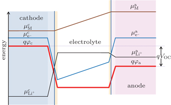
The generation of voltages in lithium-ion batteries occurs at electrode–electrolyte interfaces as a result of thermodynamic equilibrium which requires equal energies of the Li + , electrons and neutral species in the adjacent phases. [ 4 , 5 ] Different electrical energies of the charged species (Li + ) have to compensate differences in their chemical potentials. When the electrode material is brought in contact with the electrolyte, diffusion of all mobile species will occur from the phase of higher chemical potential to the one of lower chemical potential. This process continues until the transport of the charged species will build up an effective electrical field from the electrode material (space charge region), across the interface to the electrolyte (double layer), in which further diffusion will become counter-balanced. In this case, the electrochemical potentials of all the species (which are involved in lithiation/ delithiation reactions) in the electrode materials equals that in electrolyte. Inside the electrolyte, the chemical potential of the lithium ions remains constant while the chemical potentials of the neutral mobile species and electrons decrease with a constant gradient from the anode to the cathode. [ 4 , 5 ] As these species have very low concentration in the electrolyte phase, small concentration changes will cause large difference of the chemical potential. Figure
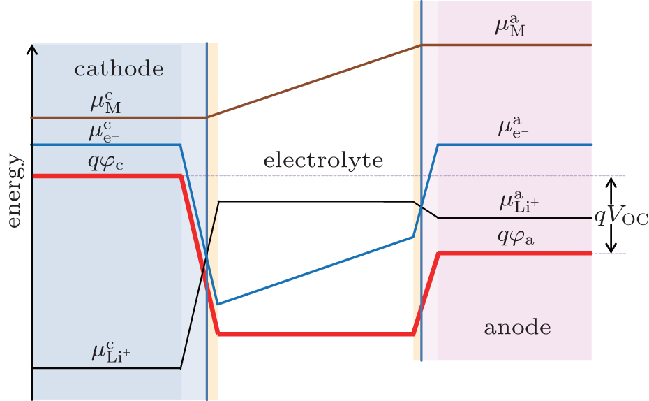 | Fig. 1. Chemical potentials of the the neutral mobile component (M), mobile ions (Li + ), and electrons (e − ) in both the cathode and anode, and electrostatic energy ( φ ) across a lithium-ion battery at open-circuit state in the absence of solid electrolyte interface (SEI). [ 4 , 5 ] |
All voltage drops occur across the interfaces between the electrodes and electrolyte because there is practically no electrical field built up in the bulk materials considering the large quantities of ionic and electrical species in the bulk phases of both electrodes and electrolyte. This happens when the electrodes are reasonably good electronic conductors and the electrolytes are reasonably good ionic conductor. [ 5 , 6 ] The electron energy levels can be determined by photoemission spectroscopy (PES) such as x-ray photoelectron spectroscopy (XPS) and ultra-violet photoelectron spectroscopy (UPS). The ion energy level can be deduced by probing the electric field inside a phase or at the interface. [ 7 ]
The rate of charge and discharge reactions of lithium-ion batteries are determined by several kinetic processes, which include: [ 8 ] (i) electron transfer between electrode materials and the current collectors; (ii) transport of electron and lithium ion in the electrode materials; (iii) transport of ions in the non-aqueous electrolyte; (iv) interfacial transfer of electrons between the electrode and electrolyte; (v) phase transition in the electrode materials caused by lithiation or delithiation. Process 1 is usually optimized to be fast for commercial battery. The rate of processes 2 and 3 can be increased by engineering means, which mainly involve reducing the distance of transport length. Process 4 is less well understood. The electrochemical equilibrium of Li + and the electrical potential gradient at the interface between the electrode materials and electrolyte determine the overall electrode potential. Other ionic species at the interface, however, are far from equilibrium. The lack of equilibrium provides a driving force for dissolution, electrolyte decomposition, and the solid electrolyte interface (SEI) formation. [ 6 ] Future development of high-voltage cathode materials, alloy and conversion reaction based anode materials, as well as improvement of battery safety and cycle life hinges on a better understanding of interfaces.
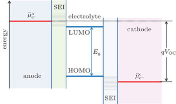
In Fig. 


 | Fig. 2. Open-circuit energy diagram of lithium-ion battery in the presence of SEI. |
In an ideal lithium-ion battery, where no side reactions occur, lithium ions can be reversibly shuttled between the anode and cathode with 100% efficiency. In reality, however, electrolyte decomposition and SEI formation consume lithium ions and convert them into “electrochemically inactive” lithium compounds (in rare cases, the SEI may have limited reactivity upon charging or discharging), resulting in permanent capacity loss. [ 1 ] Even though the SEI can prevent the electrolyte from further decomposition, it also slows down the transfer of Li + at the interfaces during cycling. [ 11 ] As a result, the cell will have higher impedance and lower cycling efficiency, especially at reduced temperatures. Moreover, decomposition of electrolyte may be accelerated at high temperature, causing fire or possibly explosion, a severe safety concern of lithium-ion battery. The formation and growth of SEI, thereby the battery performance, can be affected by the composition of electrolyte and the cycling temperature during operation. [ 12 ] In order to improve the performance of lithium-ion batteries, the surface of the electrode materials and the properties of the electrode/electrolyte interface need to be well tuned.
In commercial electrolytes with organic carbonates as solvents, the SEI is generally formed on graphite anode and lithium transition metal oxides cathode during the initial charging process of a fresh lithium-ion battery. The SEI layer consists of organic and inorganic decomposition products of the electrolyte. A few commonly agreed inorganic decomposition products include LiF, Li 2 O, and Li 2 CO 3 . [ 1 ] SEI formed on cathode materials is usually thinner initially compared to that on graphite, but it tends to increases at a higher rate upon prolonged cycling or at elevated temperature aging. [ 6 , 10 ]
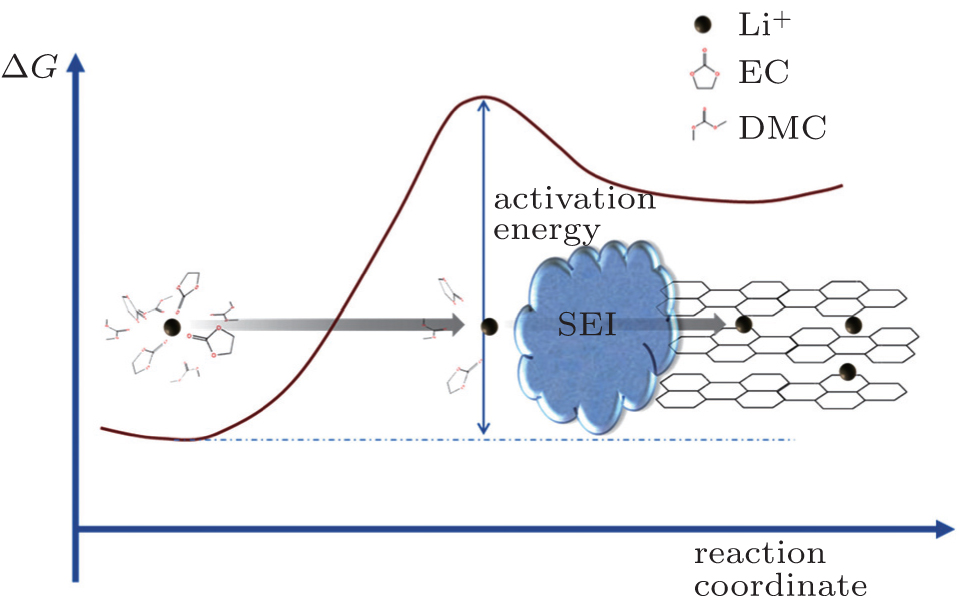 | Fig. 3. Schematic of the energetic coordinates for charge transfer at the graphite/electrolyte interface. Li + de-solvation is followed by its subsequent migration through the resistive interface. |
The charge transfer process at the electrode–electrolyte interface was generally identified as one of the rate-determining steps in the kinetics of lithium-ion battery, with an activation energy of 50–70 kJ·mol −1 for the case of graphite electrode. [ 13 ] Abe and Ogumi proposed that the de-solvation of Li + before it enters the graphite structure is the most sluggish step. Subsequent studies by these authors [ 8 , 14 , 15 ] and Xu [ 16 – 18 ] provided corroborative evidence to this speculation, further delineating the step into two sub-processes, which are the de-solvation of Li + at the interface and the subsequent diffusion of the naked Li + through the resistive SEI, [ 18 ] as shown in Fig.
Studies on charge transfer on the surface of active materials without SEI are relatively few, presumably because the most commercialized materials do not fall into this category. Li 4 Ti 5 O 12 and LiFePO 4 are the two important active materials on which it is generally considered that SEI is absent at the operation conditions of the two materials.
The potential of Li 4 Ti 5 O 12 (or LTO) lies at around 1.55 V vs. Li/Li + , well above the reduction decomposition potential of most organic carbonate solvents, and it is assumed that no SEI is formed on the surface of LTO. Xu et al . [ 18 ] observed that the ac impedance spectra of LTO contain only one semicircle instead of two as those on graphite electrodes. The missing semicircle at high frequency is due to the absence of the migration process of Li + in the SEI layer. Therefore, the de-solvation process of Li + is solely responsible for the activation energy barrier of the charge transfer process on LTO electrodes (∼ 50 kJ·mol −1 ). This value is 20 kJ·mol −1 less than that on graphite electrodes and it is consistent with the theory that the de-solvation process of Li + is the most energy consuming step in the interfacial charge transfer process. A similar study was done on anatase TiO 2 with activation energy of around 20 kJ·mol −1 . [ 21 ]
Solvent also plays an important role in the activation energy of the interfacial charge transfer process. Studies have shown that in the presence of SEI, a higher ratio of ethylene carbonate (EC)/dimethyl carbonate (DMC) (up to a certain point) increases the activation energy of the interfacial charge transfer process. [ 16 , 18 ] The higher activation energy is attributed to stronger interactions between EC and Li + and different SEI structures formed. In the absence of SEI on LTO, replacing EC/DMC with 3-methoxypropionitrile (MPN) results in much smaller charge transfer resistance. [ 22 , 23 ] This is a result of weaker interactions between the MPN and Li + , as compared to that of EC/DMC.
LiFePO 4 is another active material that has a stable surface in contact with the electrolyte during cycling. Unlike various lithium transition metal oxides, such as LiMn 2 O 4 , LiCoO 2 , and LiNi 0.8 Co 0.2 O 2 , no decomposition products are detected on LiFePO 4 surface. [ 24 , 25 ] The activation energy of charge transfer on the LiFePO 4 /electrolyte interface was reported to be ∼ 15 kJ·mol −1 . [ 26 , 27 ]
The extensive study of reversible redox mediators in lithium-ion batteries started from overcharge protection, where suitable redox shuttle additives dissolved in the electrolyte or embedded in the separator were employed to bypass the charges via reversible redox reactions. The redox shuttle molecules are either oxidized at the cathode [ 28 ] or reduced at the anode, [ 29 ] when a critical cell voltage is attained driving the cell into overcharge (or overdischarge). The mobile reaction product diffuses through the electrolyte to the counter side of the cell where the reverse electron-transfer reaction recycles it to its original state. The net effect is an internal shunt which prevents deterioration of the cell by imposing a limit on cell voltage. It is interesting to note from these studies that, while the SEI could effectively passivate both the anode and cathode (likewise, the current collectors are assumed to be covered by SEI) to prevent electrolytes from further decomposition, the reactions of redox shuttle molecules are not effectively precluded. Such a kinetically “selective” behavior of SEI towards interfacial redox reactions makes it possible for a broad range of battery materials to work with suitable redox mediators for various applications.
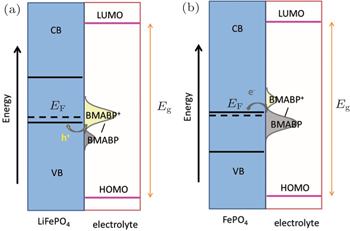
Immobilised redox relay molecules have been attempted to enhance the interfacial charge transfer process of battery materials and eliminate the use of carbon additives. Compared with conductive polymers, the relay molecules have greater flexibility in tuning the redox potential. For instance, judiciously synthesized 4-[bis(4-methoxyphenyl)amino]benzylphosphonic acid (BMABP) molecule has an identical redox potential to that of LiFePO 4 in an EC/DEC (1:1) electrolyte containing 1 M LiPF 6 . A monolayer of BMABP could be easily formed on the surface of LiFePO 4 via the chemical adsorption of phosphonic acid group. Upon operation, the surface grafted BMABP molecules will be oxidized/reduced via cross-surface lateral h + percolation. The change in the concentrations of the surface immobilised BMABP and BMABP + shifts the equilibrium redox potential of the molecule and provides the driving force for hole injection into the valance band of LiFePO 4 during charging process and electron injection into the conduction band of FePO 4 during discharging process, as illustrated in Fig.
 | Fig. 4. Band diagram and density of electronic states curves of the BMABP grafted LiFePO 4 . (a) Charging of cathode by hole injection from BMABP + into the valance band (VB) of LiFePO 4 . (b) Discharging of cathode by electron injection from BMABP into the conduction band (CB) of FePO 4 . [ 30 ] |
Alternative to the molecular wiring approach, redox polymers with tethered redox relay molecules have also been studied to solve the stability problem of the surface-grafted redox molecules, which easily come off upon prolonged operation. For instance, redox polymer consisted of poly(4-vinylpyridine) and phenoxazine moiety tethered with a C 11 alkyl chain (PVP-DD-PXZ) was employed to wire the LiFePO 4 (see Fig. ). [ 32 ] As the polymer could form robust electrode sheet with the material, no additional binder is required. The tethered phenoxazine molecules “swing” and transfer charges from the current collector to the material. Besides redox polymers, conjugated conducting polymers have also been applied on cathode materials to replace carbon black and inert polymer binder, meanwhile increase the rate capability. [ 33 , 34 ] Charges propagate in the conductive polymer phase by thermally activated electron hopping between adjacent sites, and are compensated by the diffusion of counter-ions in the electrolyte. Ideal conductive polymers have to be electrochemically stable in the operation window and with good electronic conductivity. [ 35 ] Several conductive polymers have been investigated in lithium-ion batteries, including polypyrrole (PPy) [ 33 , 34 , 36 – 38 ] and poly(3,4-ethylenedioxythiophene) (PEDOT). [ 39 – 42 ]
Desorption of the surface relay molecules and swelling of the redox polymer from the active materials lead to poor electrical contact and consequently limits the cycling performance of battery. Moreover, the rate capability of the grafted electrode is substantially constrained by the small cross-section for lateral charge percolation and by the small driving force for interfacial charge transfer. To circumvent the above issues, redox targeting of battery materials using mobile redox mediators dissolved in the electrolyte was introduced (see Fig.
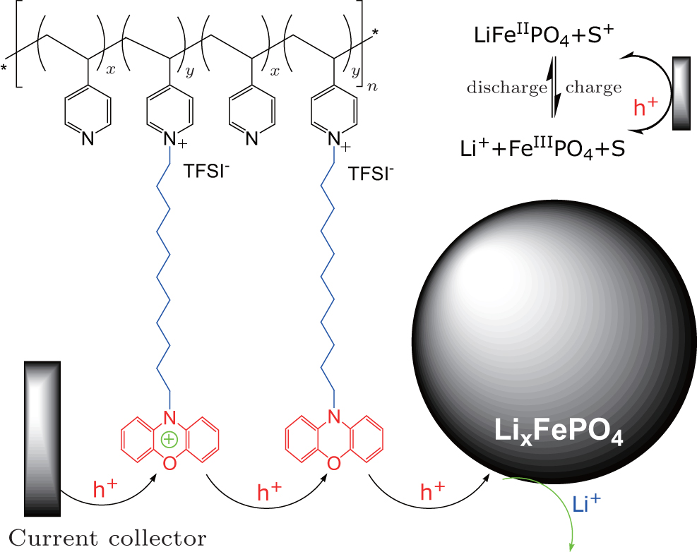 | Fig. 5. Schematic illustrating the polymer wiring of insulating electrode material LiFePO 4 . Redox polymer poly(4-((10-(12-dodecyl phenoxazine)vinylpyridinium)-co-4-vinylpyridine) in a molar ratio of 6:1 ( y / x = 5) is wrapped on the surface of the material. [ 32 ] |
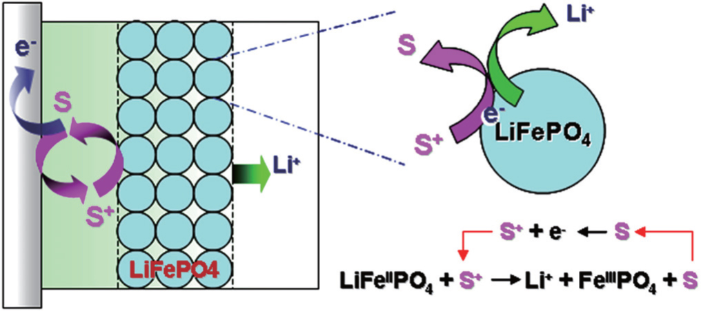 | Fig. 6. Schematic showing the working principle of redox targeting of LiFePO 4 by a freely diffusing redox mediator |
In order for redox targeting to work, the chosen redox mediators must have standard redox potentials that straddle the Fermi energy of the active materials. For instance, two osmium polypyridyl complexes ( 


In a follow-up study, the reaction rate between another pair of redox mediators, 1,1’-dibromoferrocene (FcBr 2 ), ferrocene (Fc), and LiFePO 4 were determined by applying a one-dimensional diffusion-reaction model. [ 43 ] The 

Besides LiFePO 4 , redox targeting of anatase TiO 2 has also been investigated. [ 44 ] As the lithiation/delithiation potential of TiO 2 is ∼ 1.80 V vs. Li/Li + , a different pair of redox mediators cobaltocene (CoCp 2 ) and bis(pentamethylcyclopentadienyl)cobalt (CoCp* 2 ) with potentials straddling that of TiO 2 were selected as the redox mediators for the chemical lithiation/delithiation of the material. Upon discharging, the reduced CoCp* 2 generated on current collector further reduces TiO 2 and Li + is inserted; upon charging, the oxidized CoCp 2 further oxidizes the lithiated TiO 2 and Li + is extracted. As a result, TiO 2 could be reversibly lithiated and delithiated via redox targeting reactions with the two suitable redox molecules.
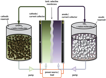
In conventional lithium-ion batteries, active materials are coated on current collector with binder and carbon additives in order to form robust electrode sheets. Redox targeting of poorly conducting battery materials can eliminate the need for carbon additives and offers a new design concept for high-energy batteries. As described in the previous section, in the presence of suitable redox shuttle molecules, an active electrode material can be charged/discharged via redox targeting reactions without being attached to the current collector. The exchange of electrons between the active material and the electrode (current collector) is mediated by the diffusion of redox shuttle molecules in the electrolyte. The application of redox targeting to both cathode and anode leads to a novel energy storage device — the redox flow lithium battery (RFLB, Fig.
 | Fig. 7. Schematic of redox flow lithium battery (RFLB). |
The configuration of RFLB contains three major components. The first component is an electrochemical cell — the power unit, consisting of two electrodes separated by a Li + -conducting membrane. The electrode is made of high surface area materials (e.g., carbon cloth) loaded with electrocatalysts, if necessary, to facilitate the extraction of charges from the redox shuttle molecules. The second component is the energy storage unit — two energy tanks, where the active electrode materials are stored and imbued with suitable redox electrolytes in their pores. These two energy tanks are electrically connected with the power unit by the circulating redox electrolyte fluids. The third unit is the control system, which includes two pumps for circulating the redox electrolytes between the energy tanks and the electrochemical cell. The control unit therefore feeds the recharged redox shuttle molecules in the energy tanks to the electrode compartments in the power unit where redox reactions occur to produce the electricity.
Since the concept of RFLB was first proposed in 2013, various RFLB cathodic and anodic half cells have been demonstrated. [ 2 , 44 ] With the development of viable Li + -conducting membranes, RFLB full cell has recently been reported by combining the two half cells with LiFePO 4 as the cathodic and anatase TiO 2 as the anodic Li + -storage material, respectively. [ 45 ] Under non-optimized conditions, the RFLB demonstrated an energy density, which is ∼ 5 times the prevailing vanadium redox flow battery. It is anticipated that the energy density could be further enhanced with more suitable redox mediators paired with Li + storage materials.
Owing to the unique working principle and operating mode, the RFLB is poised to have significant advantages over other types of electrochemical energy storage devices in terms of energy density, safety, and operation flexibility for large-scale stationary and automotive energy storage: As energy is stored in solid phases similar to a lithiumion battery, the energy density of RFLB can be 10 times as high as the conventional redox flow batteries. In addition, compared with the commercial lithium-ion batteries and the recent semi-solid lithium rechargeable flow batteries, [ 46 ] binder and bulky conducting additives are not required. Hence energy density can be further increased. The comparison of RFLB with other types of flow battery technologies has been reviewed elsewhere. [ 47 ] RFLB has greater tolerance to the volume variations of electrodes during repeated lithiation/delithiation cycles — the most challenging technology barrier for achieving long cycle life. RFLB has greater tolerance to overcharging/overdischarging and hence safety since the active materials are not directly charged or discharged. Compared with the recent semi-solid lithium rechargeable flow batteries, the fluids in RFLB are liquid redox electrolytes, just resembling that of the conventional redox flow batteries. Less energy consumption is expected. The structure of RFLB enables fast recharging, since the active materials are stored externally and separately. An RFLB can be readily “recharged” by replacing the discharged energy tanks with the charged ones (similar to refilling the fuel tank of an internal combustion engine vehicle), while simultaneously recovering the spent materials for re-energization, which is especially appealing for EV applications. As the energy storage unit is decoupled from the power unit, RFLB offers greater flexibility for modular design to achieve desired operating voltage and current, without altering the energy storage unit. RFLB has much greater feasibility for manufacturing as compared to the conventional battery technologies, where each cell in a series-connected battery pack is required to have the same state of charge (capacity) so as not to cause overcharge/overdischarge. It is much less demanding in RFLB since all the energy is stored in a single energy storage unit, and shared by modular designed power units.
While promising, one barrier for RFLB technology is the Li + -conducting membrane. The currently reported ceramic and polymeric membranes are either chemically instable or too resistive to deliver practical power. This has to be addressed before RFLB becomes a viable solution for high-density large-scale energy storage. It is noted that similar Li + -conducting membranes are also desired for other new generation lithium batteries, such as all-solid-state lithium battery, Li–O 2 and Li–S batteries. We believe that with the efforts from the battery community, new Li + -conducting membrane can be foreseen in the near future.
Research in recent years has shown that the process of interfacial charge transfer can be the rate determining step in the reactions of lithium-ion battery. The formation of SEI on the electrode materials further impedes the charge transfer process. Development of electrode/electrolyte combinations with superior dynamics, together with redox-assisted processes, will be an interesting way of enhancing the performance of lithium-ion battery.
Redox targeting of battery materials represents a novel and intriguing process in lithium-ion batteries. The redox flow lithium battery based on the redox targeting concept provides an implementable means for high-density large-scale energy storage. It is worth noting that, besides lithium-ion battery chemistry, the concept could be feasibly applied to other battery chemistries, such as Li–S [ 48 ] and Li–O 2 [ 49 ] batteries. For instance, redox flow Li–O 2 battery has recently been reported to address the surface passivation and pore clogging problems of the cathode. We anticipate that more studies emerge in the near future to explore various redox-assisted approaches for new generation electrochemical energy storage.
| 1 | |
| 2 | |
| 3 | |
| 4 | |
| 5 | |
| 6 | |
| 7 | |
| 8 | |
| 9 | |
| 10 | |
| 11 | |
| 12 | |
| 13 | |
| 14 | |
| 15 | |
| 16 | |
| 17 | |
| 18 | |
| 19 | |
| 20 | |
| 21 | |
| 22 | |
| 23 | |
| 24 | |
| 25 | |
| 26 | |
| 27 | |
| 28 | |
| 29 | |
| 30 | |
| 31 | |
| 32 | |
| 33 | |
| 34 | |
| 35 | |
| 36 | |
| 37 | |
| 38 | |
| 39 | |
| 40 | |
| 41 | |
| 42 | |
| 43 | |
| 44 | |
| 45 | |
| 46 | |
| 47 | |
| 48 | |
| 49 |