Frequency doubled femtosecond Ti:sapphire laser with an assisted enhancement cavity
Beijing National Laboratory for Condensed Matter Physics, Institute of Physics, Chinese Academy of Sciences, Beijing 100190, China
† Corresponding author. E-mail: hnhan@iphy.ac.cn
‡ Corresponding author. E-mail: zywei@iphy.ac.cn
Project supported by the National Basic Research Program of China (Grant Nos. 2013CB922401 and 2012CB821304) and the National Natural Science Foundation of China (Grant No. 61378040).
1. Introduction Optical frequency extension and conversion have been extensively studied as one of the most important fields in laser technologies. They have extremely extended the wavelengths, and become more and more important especially in some applications where a required wavelength cannot be generated by available laser sources. One of the cases is the extension to the extreme ultraviolet (XUV) region of the femtosecond frequency comb. [ 1 , 2 ] In this case, a higher laser intensity is needed to enhance the nonlinear process and preserve the high repetition rate, however, the conventional method such as cavity dumping [ 3 ] and chirped pulse amplification [ 4 ] could not meet this requirement, which restricts the conversion of the frequency comb into the wavelength of the XUV region. With the scheme of resonant enhancement, the intracavity laser intensity can be increased by several hundred times without the sacrifice of the repetition rate, and the XUV frequency comb could be realized with a repetition rate of MHz or GHz. Meanwhile, the scheme of resonant enhancement is also used frequently in the field of direct frequency comb spectroscopy (DFCS). [ 5 , 6 ] The long lifetime of the high-finesse femtosecond enhancement cavity can greatly strengthen the effective interaction between the optic field and the substance, and the wide spectrum of the femtosecond laser can help us obtain more information about the spectral lines when we detect the atoms and the molecules. The combination of the femtosecond laser and the enhancement cavity results in very high resolution and accuracy in spectrum detection. On the other hand, the combination of the enhancement cavity and the frequency conversion greatly improves the nonlinear conversion efficiency, which leads to the application of the enhancement cavity in the frequency doubling of continuous wave (CW) laser and picosecond laser. [ 7 , 8 ] Besides, single-photon detection also benefits from the scheme of enhancement cavity. [ 9 ]
In this paper, we study a femtosecond enhancement cavity, in which we adopt a pulse duration of 80 fs to diminish the effect on coherent addition by intracavity dispersion. The femtosecond laser is enhanced up to 24 times at a repetition rate of 170 MHz. Based on this structure, we place a piece of BBO crystal at the cavity focus for second harmonic generation (SHG).
2. Experimental setup The experimental setup is shown in Fig. 1 . At first, we constructed an external ring cavity consisting of four optical mirrors without the BBO crystal at the focus, a home-made femtosecond oscillator was used as the seed laser with a pulse duration of 80 fs, a repetition rate of 170 MHz, the center wavelength at 826 nm, and an output average power of 1 W. The pulses generated by the oscillator passed through two lenses for mode matching and finally entered into the passive enhancement cavity. A half-wave plate and a Faraday rotator were used to adjust the polarization and impede the interference to the oscillator by the light returning from the crystal, respectively. After the two components, the input laser power decreased to 900 mW. M1 was the input coupler for which the reflection was 99% at 800 nm, M2 and M3 were high reflection mirrors whose curvature radii were 100 mm with a reflection of more than 99.9% at 800 nm. M2 was a chirped mirror with a group delay dispersion (GDD) of −70 fs 2 at 800 nm, and it was used to compensate for the normal dispersion resulting from the input coupler and the air inside the cavity. M4 was a high reflection mirror with a reflection of more than 99.9% at 800 nm, and it was attached to a piezoelectric transducer (PZT). We could scan the cavity length periodically or lock the cavity length by using a circuit to drive the PZT.
Two photo diodes (PD1, PD2) were placed in the reflected direction of M1 and in the transmitted direction of M2, respectively. PD1 received part of the light diffracted from a grating of 1200 lines/mm and was linked to an oscilloscope, so we could monitor the signal of the reflected light. The electronic signal generated from PD2 was sent to a mixer to generate the error signal by mixing the frequency with the local signal, and after the process of proportional-integral (PI), the error signal was converted into a direct-current (DC) control signal to lock the cavity length.
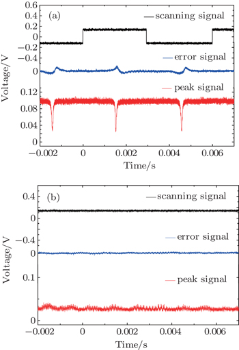
3. Results and discussion We use the Pound–Drever–Hall (PDH) method [ 10 ] to lock the cavity in the experiment. We need to find the peak signal, which is the signal of the resonance status before locking the cavity. By applying a periodical voltage to the PZT, we can make it stretch out and draw back periodically. Meanwhile, by adjusting M4 accordingly, we can obtain a peak signal (red line), as shown in Fig. 2(a) . Under the condition of zigzag scanning (black line), the dipolar error signal (blue line) is generated. For the peak signal, it is downward in the reflected direction of M1 and upward in the transmitted direction of M2, these two are consistent with each other. The peak signal implies that the cavity length matches the repetition rate of the input pulse, in other words, the pulse after one round trip in the cavity can be added coherently to the next pulse and the pulses are resonant in the cavity. By locking the cavity length at this position, we keep the pulses in resonance. The power of the leakage light is detected to be 480 μW by the power meter behind M3, and M3 has an accurate reflection of 99.998%. Therefore, we can conclude that the intracavity average power is 24 W, which means that the power in the cavity is enhanced by up to 24 times compared with that of the input laser. Figure 2(b) shows the signals on the oscilloscope after locking.
During the locking, we monitor the power of the reflected light from M1 as well as the leakage power. In ideal circumstances, when the pulses in the cavity are well resonant, the input laser will be completely coupled into the cavity and the reflected light will disappear after locking, correspondingly, the voltage signal on the oscilloscope due to the reflected peak signal decreases to zero. In the experiment, the voltage signal of the reflected peak signal (red line) is above zero, as shown in Fig. 2(b) . This means that there is still some reflected light remaining in our experiment. This phenomenon well explains why the enhancement is not very high, so we will try to solve this problem of coupling, and we believe that the enhancement will be much greater.
Then according to the experimental setup and the enhancement results above, we place a 2-mm-long BBO crystal at the focus of the enhancement cavity. The absorption of the 800 nm laser by the BBO crystal increases the intracavity loss. According to the impedance matching principle, only when the transmission of the input coupler is consistent with the intracavity loss, can the enhancement factor be largest, so the reflection of the input coupler should be decreased accordingly. Following the analysis described in Refs. [ 11 ] and [ 12 ], in which the loss is determined by the nonlinear conversion of the fundamental into the SHG in a low-loss cavity with an SHG crystal, we can obtain a crystal transmission term t SH which is given by

and the enhancement factor of the fundamental power which is given by

Here,
γ SH is the nonlinear conversion factor of the fundamental frequency to the SHG,
P 1 is the incident power,
P C is the intracavity circulating power,
r 1 is the reflectivity of the input coupler, and
r 2 is the total reflectivity of the cavity exclusive of the input coupler. Equation (
2 ) indicates the impedance-matched condition

under which the enhancement is maximum. Then the expected SHG power can be obtained from

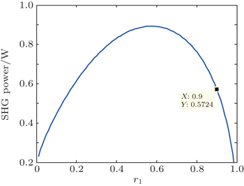
Figure 3 shows the calculated dependence of the SHG power on the reflection of the input coupler with a single-pass conversion factor of 0.2 W −1 for the BBO crystal and a total reflection of 99% of the cavity excluding the input coupler under an incident power of 900 mW. It indicates that the enhancement is best when the reflection is between 50% and 70%. Owing to our limited laboratory condition, we choose an input coupler with a reflection of 90% to carry out the experiment. The calculated SHG power is 572 mW with this reflection. Here, mirrors M5, M6, and M7 are used to filter the leakage light at 800 nm, making the results more accurate. M5 is a dichroic mirror with high reflection at 400 nm and high transmission at 800 nm. M6 and M7 are mirrors with high reflection at 400 nm.
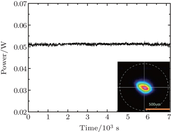
The power of the SHG is detected by a power meter behind M7, and we can obtain a stable output SHG of 51 mW after locking. We measure the transmission of M3 at 413 nm and obtain a transmission of 13%, so the intracavity SHG power can be deduced to be 392 mW. Since the coating of M3 is not designed for 400 nm, the output power of the SHG is limited. If we change M3 to a dichroic mirror with a transmission of 99% at 400 nm, then the output will be 388 mW and the conversion efficiency will be 43%. The experimental result is not in good agreement with the calculated result mainly because some fundamental frequency is not resonant due to the dispersion inside the cavity, as a result, these components cannot be converted into SHG. We measure the stability of the output over two hours and obtain a power of P SHG = 51 ± 3 mW outside the cavity, as shown in Fig. 4 . The output is stable enough with a calculated RMS of 0.039%. The inset shows the transversal mode profile of the SHG, the spot looks like an ellipse because of the walk-off effect. Figure 5 shows the SHG spectrum with a bandwidth (FWHM) of 2.7 mm at the central wavelength of 413 nm. Compared with the input spectrum of the fundamental frequency at 826 nm, the SHG spectrum is narrowed and ranges from 405 nm to 418 nm, but the intensities of two sides are too weak because the corresponding fundamental frequency is not resonant inside the cavity.
If we directly shoot the femtosecond laser into the BBO crystal to generate the SHG, we can obtain an output power of 202 mW, which is much lower than that with the enhancement cavity. The great increase of the SHG output is mainly due to the enhancement of the fundamental laser by the assisted cavity. So we conclude that it is the femtosecond enhancement cavity that makes the incident femtosecond laser enhanced greatly, and also makes the conversion efficiency of the frequency doubling increased. Because the reflection of the input coupler is not very high and the conversion efficiency of the BBO crystal is not saturable, we believe that if we adopt a new input coupler with higher transmission, the conversion efficiency will be further increased.
4. Conclusion We construct a ring cavity consisting of four mirrors and demonstrate the enhancement of the femtosecond laser with a pulse duration of 80 fs and a repetition rate of 170 MHz. An enhancement factor of 24 is obtained. With the BBO crystal inserting into the cavity, we carry out the experiment of frequency doubling with the assisted cavity and achieve an intracavity SHG output of 392 mW with a long term stability, which not only demonstrates the enhancement of the incident femtosecond laser, but also indicates that frequency doubling with an assisted enhancement cavity is an effective method to generate the SHG and the UV frequency comb.


 , Hou Lei , Zhang Long , Yu Zi-Jiao , Li De-Hua , Wei Zhi-Yi ‡,