
Fiber fuse behavior in kW-level continuous-wave double-clad field laser
[Sun Jun-Yi , Xiao Qi-Rong , Li Dan , Wang Xue-Jiao , Zhang Hai-Tao , Gong Ma-Li , Yan Ping †,  ]
]
]
|
|


† Corresponding author. E-mail:
Project supported by the Key Laboratory of Science and Technology on High Energy Laser and China Academy of Engineering Physics (Grant No. 2014HEL02) and the National Natural Science Foundation of China (Grant No. 61307057).
In this study, original experimental data for fiber fuse in kW-level continuous-wave (CW) high power double-clad fiber (DCF) laser are reported. The propagating velocity of the fuse is 9.68 m/s in a 3.1-kW Yb-doped DCF laser. Three other cases in Yb-doped DCF are also observed. We think that the ignition of fiber fuse is caused by thermal mechanism, and the formation of bullet-shaped tracks is attributed to the optical discharge and temperature gradient. The inducements of initial fuse and formation of bullet-shaped voids are analyzed. This investigation of fiber fuse helps better understand the fiber fuse behavior, in order to avoid the catastrophic destruction caused by fiber fuse in high power fiber laser.
Fiber fuse, which is caused by thermal mechanism, results in catastrophic destruction in the optical fiber core in which laser light is transmitted. The fuse propagates from its original point towards the laser light source, leaving a series of single, bullet-shaped cavities in the core. Fiber fuse can be initiated by external intervention at intensity levels ranging from 1 MW/cm 2 to 3 MW/cm 2 . Compared with the intrinsic damage limit (∼ 10 GW/cm 2 ) of silica, [ 1 ] the threshold power density level of fiber fuse is, clearly, many orders of magnitude lower.
In recent years, high power fiber lasers that operate at continuous-wave (CW) have played an increasingly important role in many applications. The intensity of kilowatt output laser is at a level of a few hundred MW/cm 2 . Fiber fuse occurs more readily and causes more severe destruction under such a circumstance. It is necessary to study the fiber fuse in CW high power fiber laser to avoid triggering the fiber fuse.
Research regarding the fiber fuse first began in 1987. Since then, fiber fuse has been induced by several different ways. Direct heating is the approach that researchers most commonly utilize to trigger fiber fuse. [ 2 , 3 ] The fiber fuse was successfully triggered by contacting the fiber output end with absorbent materials. [ 1 – 4 ] Simply bending the fiber could also induce the fuse. [ 5 , 6 ] In addition to deliberate external intervention, unintentional intervention, such as absorbing impurities on the fiber output end, could induce the fuse. [ 7 ] In these experiments, laser intensities in the fiber core were between 1 MW/cm 2 to 3 MW/cm 2 and the propagating speeds of the fuses are between 0.3 m/s and 3 m/s. The fibers in which fiber fuse occurred were single-clad with core diameters less than 10 μm. Several hypotheses exist to explain fiber fuse behavior based on the experimental data available, including self-propelled self-focusing, [ 1 ] solitary thermal shock wave, [ 2 ] exothermic chemical reaction, [ 8 ] Rayleigh instability of capillary effects [ 9 ] and a two-step thermal mechanism. [ 7 ] Dianov et al. observed fiber fuse propagating with a velocity of 10 m/s in singer mode fiber under 40-W laser power. [ 10 ] However, because limited experimental data exists for fiber fuse occurrence in high power fiber laser with large mode area (LMA) fiber, the fiber fuse phenomenon is as yet unclear, especially in the kilowatt-level high power CW fiber laser.
In fact, the fiber fuse can also occur in double-clad fibers of high power fiber lasers. Wang et al. explained the thermal mechanism causing fiber fuse in the high numerical aperture (NA), Yb-doped double-clad fiber (DCF) with a core diameter of 10.5 μm. But they did not mention the characteristics of fiber fuse in high power fiber lasers, nor the output power of the fiber laser when fiber fuse occurred. [ 7 ] Zhang et al. investigated fiber fuse in a DCF with a core diameter of 30 μm. The laser power was 400 W and laser intensity was 56 MW/cm 2 when the fiber fuse was ignited. [ 11 ]
In the present paper, original experimental data for fiber fuse in a CW high power DCF laser are reported. The fiber fuse occurring in the core of the LMA double-clad fiber includes active fiber doped with ytterbium and inactive fiber doped with germanium. The propagating velocity of the fuse is 11.7 m/s when laser intensity is 541 MW/cm 2 in Yb-doped DCF. Three other fuses in Yb-doped DCF are additionally observed. The mechanisms of the initial fuse and the formation of bullet-shaped voids are analyzed, and methods of preventing fiber fuse are suggested.
A comprehensive observation of fiber fuse phenomena helps better understand the fiber fuse behavior in order to avoid the catastrophic destruction caused by fiber fuse in high power fiber lasers.
Fiber fuse occurs five times in the kW-level CW high power all-fiber laser experiments due to unintentional intervention. The experimental setup, a master oscillator power amplifier (MOPA) configuration, is shown in Fig.
The fiber fuse in the experiment is initiated in the Yb-doped DCF near the output end. A bright spark caused by fiber fuse is observed propagating in the opposite direction of the laser. Before we shut down the power supply of the fiber laser system, the fuse propagates 2–4 m in the fiber in less than 0.5 s. The fiber fuse process is recorded by a video camera. The propagating time of fiber fuse is calculated by counting the number of the frames with spark light. The length of fiber with damage track is the propagating length of fiber fuse. In the core of the fiber where fiber fuse occurs, a damage track mainly composed of bullet-shaped voids is found. The laser power, core diameter, laser intensities, and fiber fuse parameters at the point where fiber fuse occurs are listed in Table
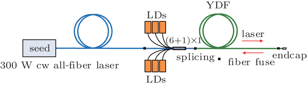 | Fig. 1. All-fiber laser system with MOPA configuration. |
| Table 1. Parameters of fiber fuse propagation. . |
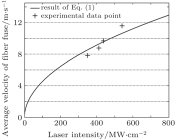
The initiation and propagation of fiber fuse can be described as a process of heat accumulation and heat transfer with a heat source. To examine the velocity of fuse propagation in the kW-level CW fiber laser, the relationship proposed by Hand and Russell [ 2 ] is utilized

For the Yb-doped DCF, ρ = 2200 kg/m 3 , C p = 1323 J · kg −1 · K −1 , κ = 9.2 W · m −1 · K −1 , α p = 3.3 × 10 4 m −1 , T t = T m = 2000 K, and T a = 298 K. The velocities ν f of the fiber fuse under different intensities in the DCF of kW-level CW fiber lasers are shown in Fig.
 | Fig. 2. Velocity of fiber fuse versus laser intensity in Yb-doped DCF of high power CW fiber laser. |
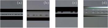
Most damage tracks of the fuse in Yb-doped DCF are bullet-shaped. Figure
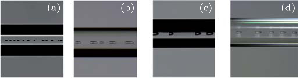 | Fig. 3. Catastrophic destructions caused by fiber fuse in CW high power Yb-doped DCF laser when I = (a) 350 MW/cm 2 , (b) 413 MW/cm 2 , (c) 438 MW/cm 2 , and (d) 541 MW/cm 2 . |
| Table 2. Sizes of bullet-shaped track. . |
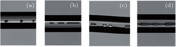
Some of the cavities in the core show less regularity, and some voids are distorted due to mechanical stress of DCF. Figure
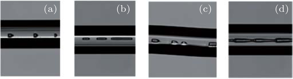 | Fig. 4. Unstable patterns in Yb-doped DCF with laser intensity being 438 MW/cm 2 . (a) Dot-shaped track; (b) line-shaped track; (c) distorted bullet shaped track; (d) indiscrete damage track. |
Though numerous hypotheses already exist which attempt to explain fiber fuse, the most common cause is considered to be the thermal mechanism. [ 1 – 3 , 12 – 14 ] All the fiber fuse initiation methods mentioned above create a hot zone with high temperature in the core.
In a fiber laser system, due to the quantum defect inherent to the process of laser amplification, most of the pump energy absorbed by the gain fiber is converted into signal light energy, while the remaining energy is emitted in the form of heat through the gain fiber. At certain points of a gain fiber, if it is not properly cooled, the generated heat causes temperature to rise as more and more laser energy is converted into heat at such points, ultimately forming hot zones where fuses are typically induced.
Considering the physical process of a typical fiber fuse, the dynamics of the fiber fuse is governed by the following set of equations: [ 12 , 15 – 19 ]


These equations, based on thermal mechanism, successfully describe fiber fuse ignition as it occurs during the experiments in this study. First, due to unintentional intervention, a hot zone emerges somewhere in the fiber, changing the laser absorption in the core of the fiber. Then, under the operation of the laser, a heat source is produced which further raises up the temperature in the fiber core. When the temperature increases up to a threshold, the absorption of the fiber core rises abruptly to a high level, leading to sharp rise in temperature. The high temperature conditions cause the core of the fiber to melt, or even to vaporize.
The thermal mechanism, however, fails to adequately explain the formation of bullet-shaped damage region. In this study, this type of damage is attributed to the optical discharge and temperature gradient, similar to previous reports by Todoroki with detailed experimental data. [ 4 , 5 ] As proposed by Yakovlenko, once the fuse is triggered, there occurs a high-density negative charge layer at the plasma-fluid border. [ 20 ] The repulsion of similar charges produces an extraneous pressure that forces out the liquid layer, forming a series of bullet-shaped tracks.
The average period and length of the voids show some patterns in DCF. However, compared with the case of the known fiber fuse in single-mode fibers, the void formation in the DCF is more unstable. Although we calculate the average speed of the fiber fuse in DCF laser, the instantaneous velocity is not identical at each position. Most parts of the damage tracks show poor periodicity in short distance. We suppose that this can be partly attributed to the fact that there are more transverse modes in the core of the DCF, and the margin of certain high-order transverse modes can exist in the inner cladding. These transverse modes make the thermal condition in the DCF different from that of a single-mode fiber. The number of transverse modes increases with the increase of laser power. In addition, during the operation of the fiber laser, we monitor the temperature of the outer surface of DCF. The highest temperature of the Yb-doped DCF, when fiber fuse occurs, is not fixed. We find that when the laser intensity becomes higher, the fiber fuse can be triggered at lower temperature. We suppose that the transverse modes of higher intensity laser may result in the uneven distribution of laser intensity, causing some part of fiber core to become overheated more easily. This means that the high-order transverse modes of DCF in high laser intensity may be responsible for the fiber fuse behavior in kW-level DCF laser.
As mentioned above, to prevent fiber fuse in the kW-level fiber laser, it is necessary to avoid hot zones in the core. In a kW-level all-fiber laser system, it is essential to select fibers that show less defects, and to keep the fiber end surface clean during the assembly process. When operating the kW-level all-fiber laser system, the temperature of the fiber must be carefully monitored for hot zones. An efficient cooling system for the fiber must be adopted. Because the velocity of fiber fuse in the high power CW fiber laser is so high, it is necessary to shut down the power supply of the fiber laser immediately upon fuse initiation in order to minimize the damage.
In this study, we report original experimental data for fiber fuse in a CW high power DCF laser. Fiber fuse is observed in a 3.1-kW fiber laser and another three with lower power. The laser intensities when fiber fuse occurs are 541 MW/cm 2 , 438 MW/cm 2 , 413 MW/cm 2 , and 350 MW/cm 2 in the Yb-doped DCF, and the propagating velocities of fuse are 11.7 m/s, 9.6 m/s, 8.5 m/s, and 7.8 m/s, respectively. The cause of the initial fuse and resulting series of bullet-shaped tracks are also analyzed. Fiber fuse is triggered due to the thermal mechanism. The formations of bullet-shaped tracks are attributed to the optical discharge and temperature gradient.
Fiber fuse phenomena provided in this paper help us to more completely understand the fiber fuse behavior, in efforts to better avoid the catastrophic destruction caused by fiber fuse in high power fiber laser.
| 1 | |
| 2 | |
| 3 | |
| 4 | |
| 5 | |
| 6 | |
| 7 | |
| 8 | |
| 9 | |
| 10 | |
| 11 | |
| 12 | |
| 13 | |
| 14 | |
| 15 | |
| 16 | |
| 17 | |
| 18 | |
| 19 | |
| 20 |