


Memcapacitor model and its application in a chaotic oscillator
[Wang Guang-Yi †,  , Cai Bo-Zhen , Jin Pei-Pei , Hu Ti-Ling ]
, Cai Bo-Zhen , Jin Pei-Pei , Hu Ti-Ling ]
|
|


† Corresponding author. E-mail:
Project supported by the National Natural Science Foundation of China (Grant Nos. 61271064, 61401134, and 60971046), the Natural Science Foundation of Zhejiang Province, China (Grant Nos. LZ12F01001 and LQ14F010008), and the Program for Zhejiang Leading Team of S&T Innovation, China (Grant No. 2010R50010).
A memcapacitor is a new type of memory capacitor. Before the advent of practical memcapacitor, the prospective studies on its models and potential applications are of importance. For this purpose, we establish a mathematical memcapacitor model and a corresponding circuit model. As a potential application, based on the model, a memcapacitor oscillator is designed, with its basic dynamic characteristics analyzed theoretically and experimentally. Some circuit variables such as charge, flux, and integral of charge, which are difficult to measure, are observed and measured via simulations and experiments. Analysis results show that besides the typical period-doubling bifurcations and period-3 windows, sustained chaos with constant Lyapunov exponents occurs. Moreover, this oscillator also exhibits abrupt chaos and some novel bifurcations. In addition, based on the digital signal processing (DSP) technology, a scheme of digitally realizing this memcapacitor oscillator is provided. Then the statistical properties of the chaotic sequences generated from the oscillator are tested by using the test suit of the National Institute of Standards and Technology (NIST). The tested randomness definitely reaches the standards of NIST, and is better than that of the well-known Lorenz system.
In 1971, Chua postulated the missing fourth circuit element which is named the memristor by using the functional relation between charge q and flux φ (d φ = M d q ). [ 1 ] Until 2008, an operational Chua memristor was finally realized by a team of researchers at Hewlett-Packard (HP) based on a thin film of titanium dioxide, [ 2 ] which has attracted immense worldwide interest from both industry and academia.
In 2009, Ventra, Pershin, and Chua extended the concept of the memrisor to memcapacitor and meminductor, which are defined by the charge–voltage relation and the current–flux relation, respectively. [ 3 ] These memory devices are common at the nanoscale, where the dynamical characteristics of ions and electrons are likely to depend on the histories of the systems that exhibit their memorability. [ 3 ] These nanoscale devices can store information without a power source, and their combination in circuits is likely to find new applications in non-volatile memory, and to simulate learning, adaptive, and spontaneous behaviors. [ 3 ] Therefore, the nanoscale memory device is becoming a new hot spot in research. [ 4 – 6 ]
In 2009, a piecewise model of the memcapacitor was presented in Ref. [ 3 ]. In fact, it has long been found that a nanoscale capacitor possesses a memory effect, and shows a capacitance–voltage or charge–voltage hysteresis characteristic, the examples include Ge nanocrystal embedded Hf-aluminate high- k gate dielectric [ 7 ] and metal oxide semiconductor structure containing nanocrystals deposited by ion-beam-assisted electron beam deposition. [ 8 ] Since then some systems with the memcapacitance property have been found, including vanadium dioxide metamaterials, [ 9 ] ionic memcapacitive effects in nanopores, [ 10 , 11 ] the analog memory capacitor based on field configurable ion-doped polymers, and the solid-state memcapacitive system with negative and diverging capacitance. [ 12 ] Especially, Ref. [ 13 ] proposed a bistable non-volatile elastic-membrane memcapacitor, which has two stable states, i.e., low and high capacitance configurations, and exhibits a chaotic oscillation with certain driven voltage amplitudes and frequencies.
Now as a memory device, the memristor has been widely studied in non-volatile memory, artificial neural networks, and nonlinear circuits such as chaotic oscillators. [ 14 – 20 ] However, compared with the memristor, the memcapacitor and the meminductor have been relatively little studied. Although actual solid-state memcapacitors and meminductors have not appeared yet, it is of significant importance to design effective equivalent models of these two elements and make prospective studies of their applications. [ 21 ]
References [ 22 ] and [ 23 ] presented piecewise linear and exponential 
We propose an HP memristor-like memcapacitor model in this paper. The reason is that the properties of memristor, memcapacitor, and meminductor are common at the nanoscale level, and thus the HP memristor-like memcapacitor model conforms more to the future real memcapacitor. Based on the memcapacitor model, a circuit model for emulating the behaviors of the mamcapacitor is constructed, and on the basis of the memcapacitor circuit model, a memcapacitor oscillator is designed. Its dynamical behaviors are analyzed and verified by theoretical analysis and circuit experiments respectively. Some special phenomena and good randomness of the oscillator are found. Furthermore, an analog circuit and a digital circuit are designed for confirming the memrcapacitor oscillator. Finally, its statistical properties are tested by the NIST standards.
Some studies have found that some micro systems can exhibit memcapacitor effects. Hence according to the model of the nanoscale HP memristor, we give a memristor-like model of the memcapacitor.
The memristance of the HP memristor can be written as [ 2 ]

Similarly, Chua defined the memcapacitor as a charge-controlled capacitor, and the relation between voltage u and charge q is described as [ 3 ]
Considering Eqs. (


Let α = 0.7, β = 3.2, and q ( t ) = Q m sin(2 π ft ), the applied voltage (blue) and the resulting charge (green) are shown in Fig.
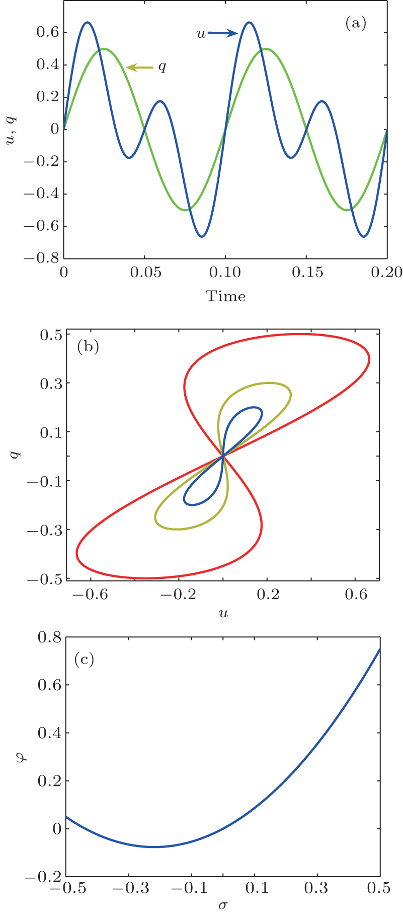 | Fig. 1. Characteristics of charge-controlled memcapacitor: (a) waves of voltage and charge, (b) voltage–charge hysteretic curves, (c) φ – σ curve. |
Figure 
 | Fig. 2. Equivalent circuits for charge-controlled memcapacitor: (a) equivalent circuit of u – q characteristic, (b) equivalent circuit of φ – σ characteristic. |
Figure
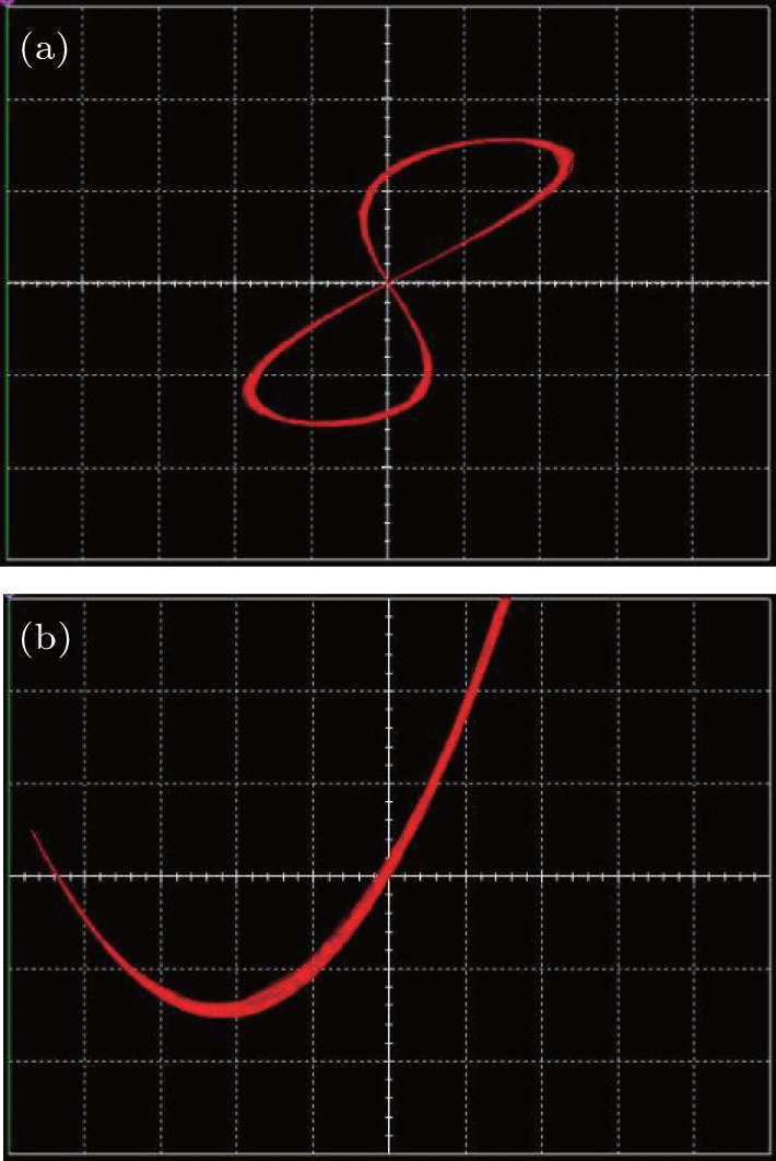 | Fig. 3. Characteristics of charge-controlled memcapacitor: (a) hysteresis u – q curve, (b) φ – σ characteristic. |
Based on Chua’s circuit and Ref. [ 24 ], a charge-controlled memcapacitor circuit is designed as shown in Fig. 
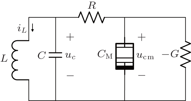 | Fig. 4. Oscillator circuit with charge-controlled memcapacitor. |
By taking the current i L through the inductor, the voltage u c across the capacitor, and the charge q m on the memcapacitor as state variables, and by applying Kirchoff’s laws to this circuit, the state equations are obtained as


When L = 0.13 H, C = 3.57 F, R = 0.21 k Ω , G = 2.1 mS, α = 0.7 F −1 , and β = 0.8 F −1 ·C −1 ·s −1 , this memcapacitor oscillator exhibits a chaotic oscillation as shown in Fig.
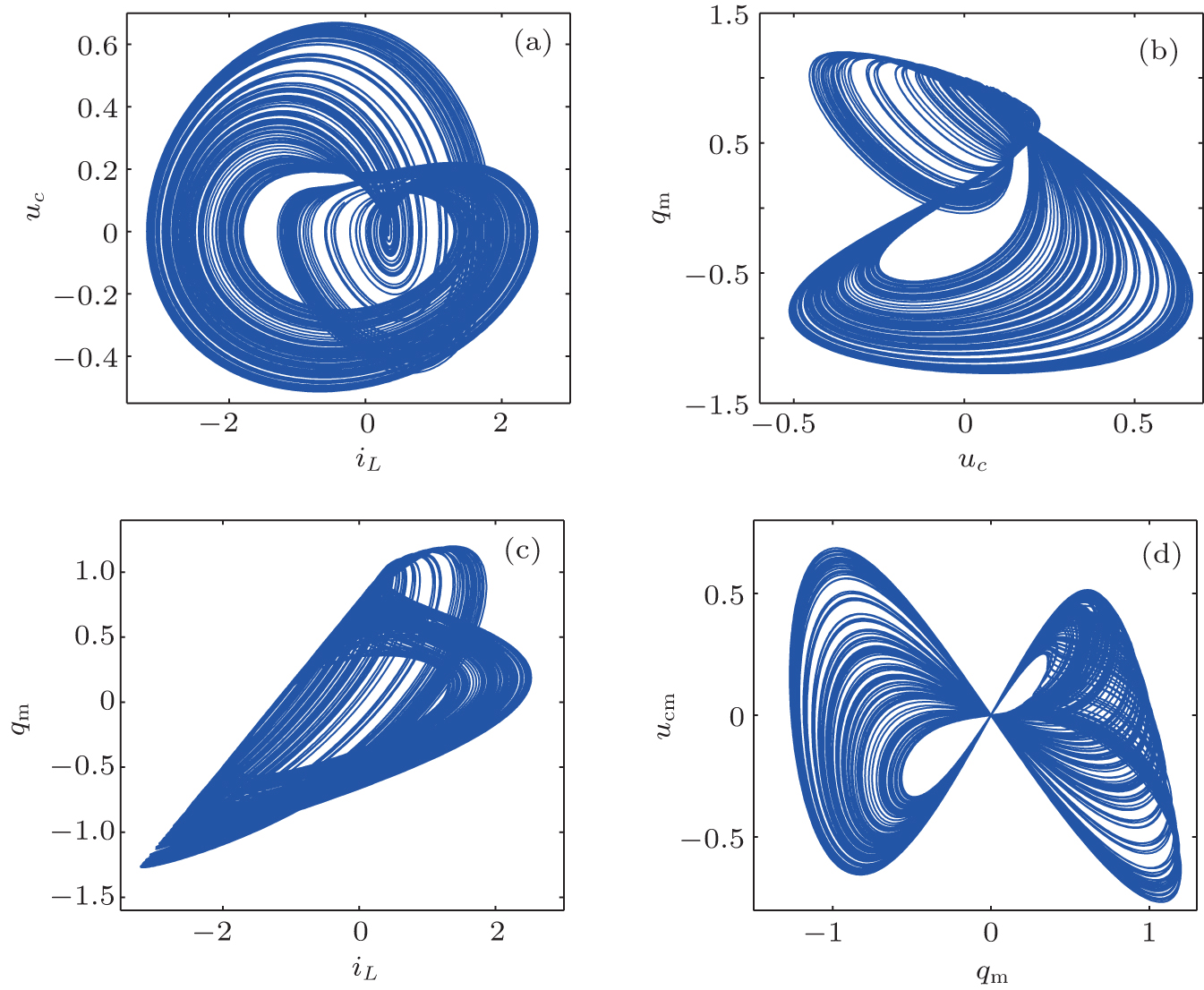 | Fig. 5. Chaotic attractors of memcapacitor-based oscillator: (a) u c – i L trajectory, (b) q m – u c trajectory, (c) q m – i L trajectory, (d) u cm – q m trajectory. |
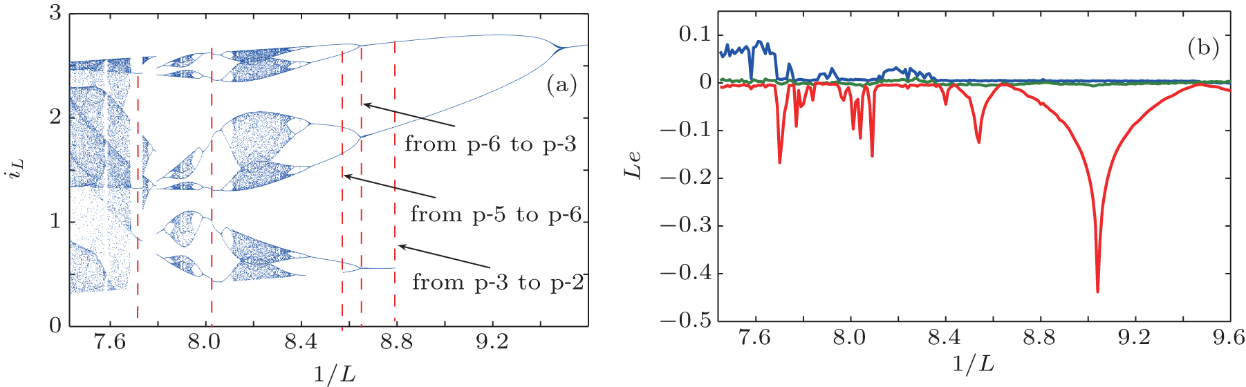 | Fig. 6. Dynamical characteristics of memcapacitor-based oscillator: (a) bifurcation plot of current i L versus inductance L , (b) Lyapunov exponents versus inductance L . |
By integrating Eq. (
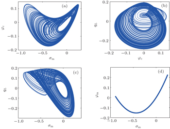
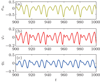
This system has a chaotic attractor with Lyapunov exponents Le 1 = 0.114, Le 2 = 0, and Le 3 = −2.2878 when m = 4.5, e = 0.48, a = 0.7, b = 0.4, and k = 1.75. The trajectories of the circuit variables are shown in Figs.
 | Fig. 7. The (a) φ c − σ m trajectory, (b) q L – φ c trajectory, (c) q L – σ m trajectory, (d) φ m – σ m trajectory. |
 | Fig. 8. Waveforms of (a) σ m , (b) φ c , and (c) q L . |
The divergence of system (

When
Let ẋ = ẏ = ż = 0, we obtain two equilibria, S 1 (0, 0, 0) and S 2 (− a/b , 0, 0). This is different from most memristor-based oscillators, which possess an infinite number of equilibria, or an equilibrium set, or a line equilibrium.
The Jacobian matrix of Eq. (

The characteristic equation for the equilibria can be written as

Solving this characteristic equation with the above given parameters, we obtain the characteristic values λ 1 = −2.8973 and λ 2,3 = 0.1297 ± 0.9862i for equilibrium S 1 , and λ 1 = 0.8363 and λ 2,3 = −0.0991 ± 1.8488i for equilibrium S 2 , displaying that both of them are unstable saddle-focus.
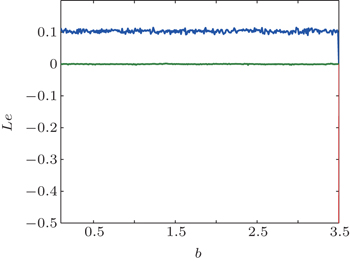
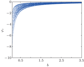
The Lyapunov exponent spectrum versus parameter b (for clarity, only the two larger Lyapunov exponents are drawn, similarly hereinafter) and the corresponding bifurcation diagrams are shown in Figs.
 | Fig. 9. Lyapunov exponents versus memcapacitor parameter b . |
 | Fig. 10. Bifurcation of flux φ c through capacitor C versus parameter b . |
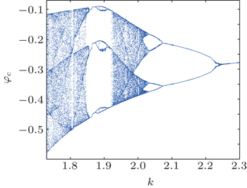
The Lyapunov exponent spectrum and the corresponding bifurcation diagram of variable y versus parameter k are shown in Figs.
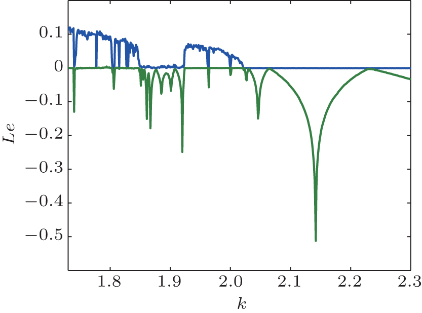 | Fig. 11. Lyapunov exponents versus parameter k . |
 | Fig. 12. Bifurcation of flux φ c versus parameter k . |
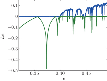
Figure
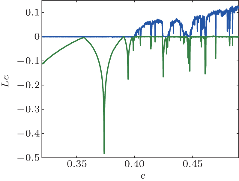 | Fig. 13. Lyapunov exponents versus parameter e . |
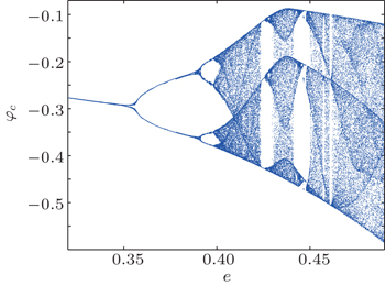
 | Fig. 14. Bifurcation of flux φ c versus parameter e . |
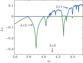
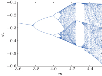
The Lyapunov exponent spectrum versus parameter m and the corresponding bifurcation diagram are shown in Figs.
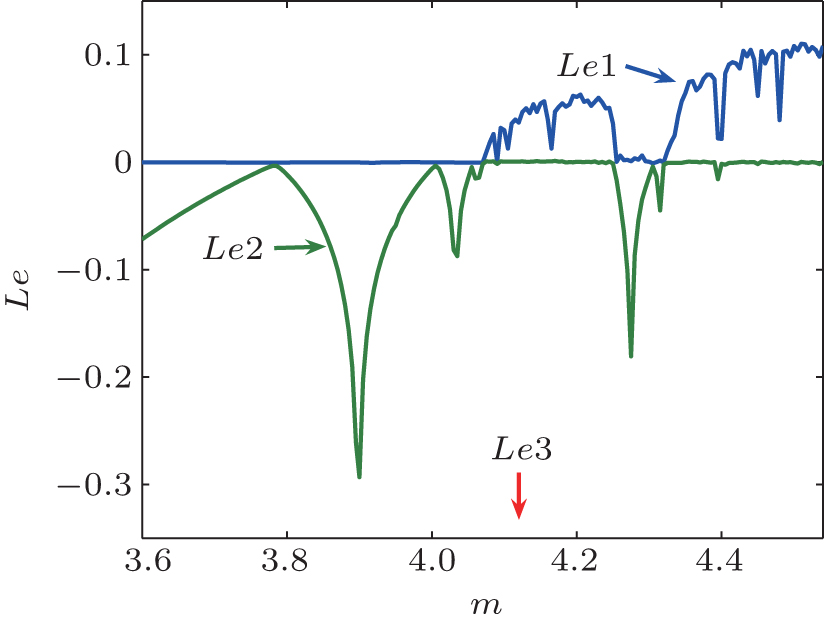 | Fig. 15. Lyapunov exponents versus parameter m . |
 | Fig. 16. Bifurcation of flux φ c versus parameter m . |
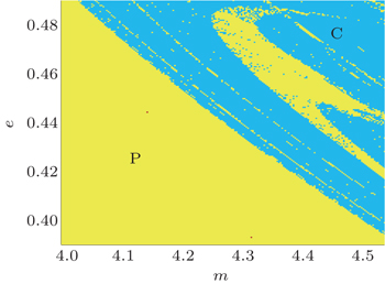
Now we present the dynamical map of system (
 | Fig. 17. Dynamical map with parameters m and e . |
 | Fig. 18. Poincare section for φ c = 0. |
In this section, we give two analog circuit schemes for realizing the proposed memcapacitor oscillator based on the u – q characteristic and the φ – σ characteristic of the memcapacitor, respectively.
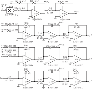
The memcapacitor oscillator circuit, which is designed according to the u – q model (i.e., Eq. (
 | Fig. 19. Memcapacitor oscillator based on the u – q circuit model. |
 | Fig. 20. Simulated experimental results: (a) i L – u c phase diagram, (b) u c – q m phase diagram, (c) i L – q m phase diagram, (d) q m – u cm phase diagram. |
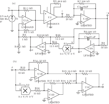
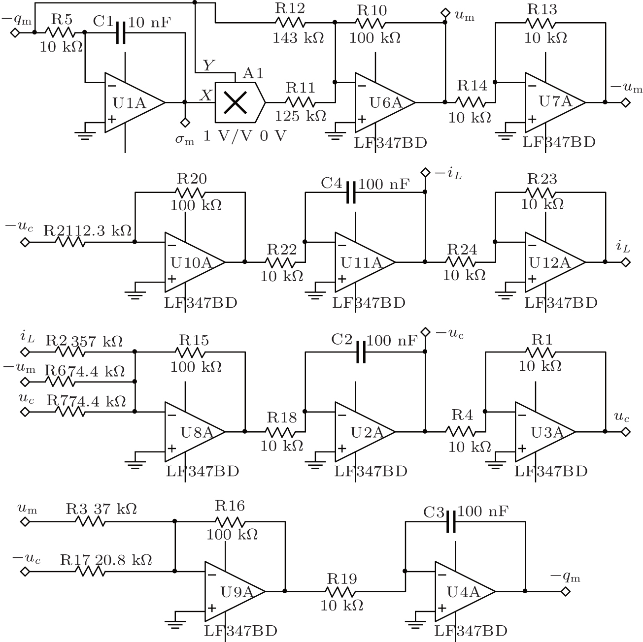
On the other hand, the memcapacitor oscillator circuit designed according to the φ – σ characteristic (i.e., Eq. (
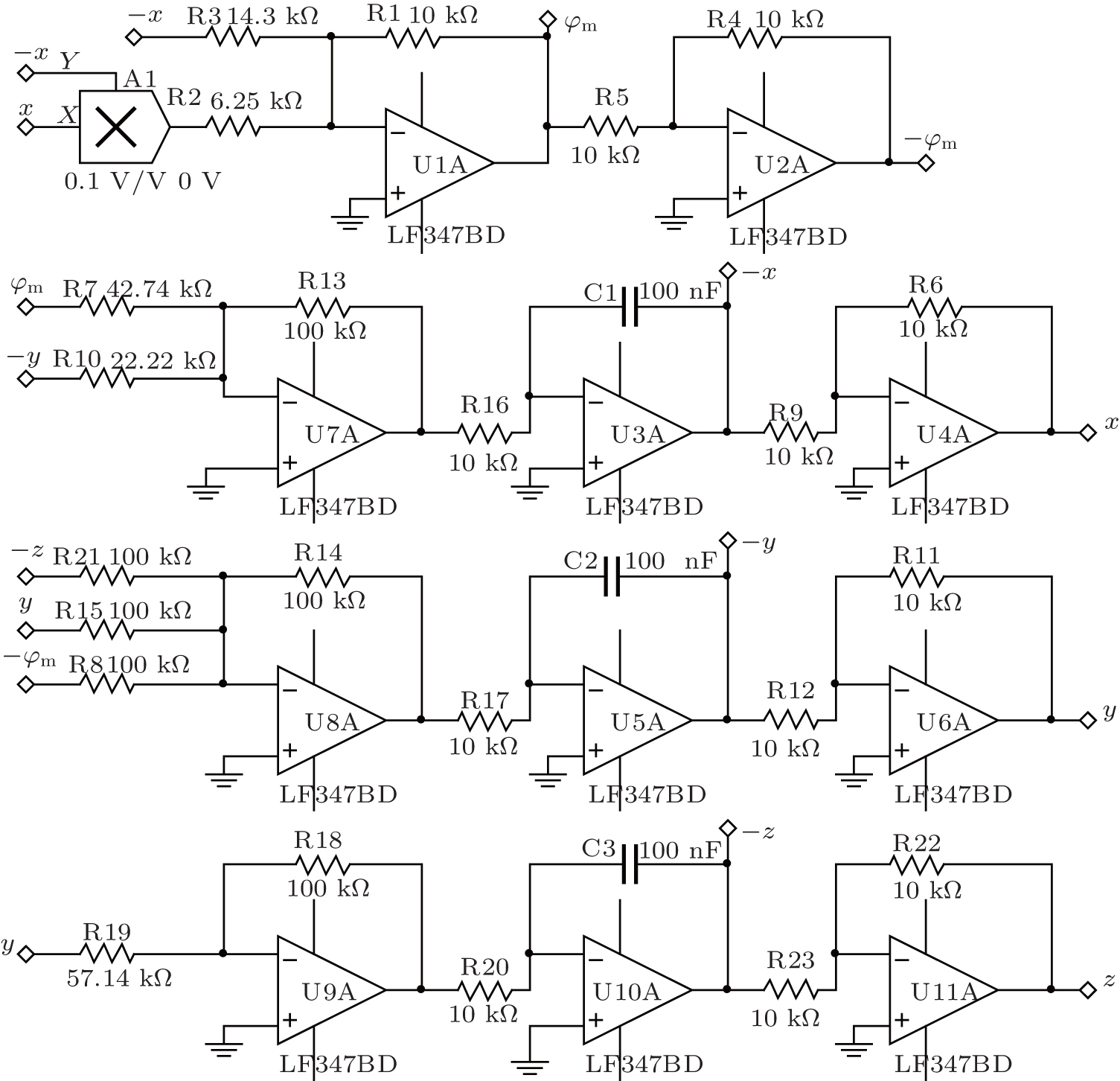 | Fig. 21. Memcapacitor oscillator based on the φ – σ circuit model. |
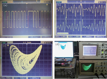
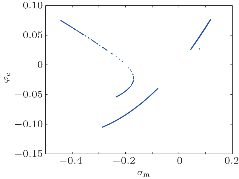
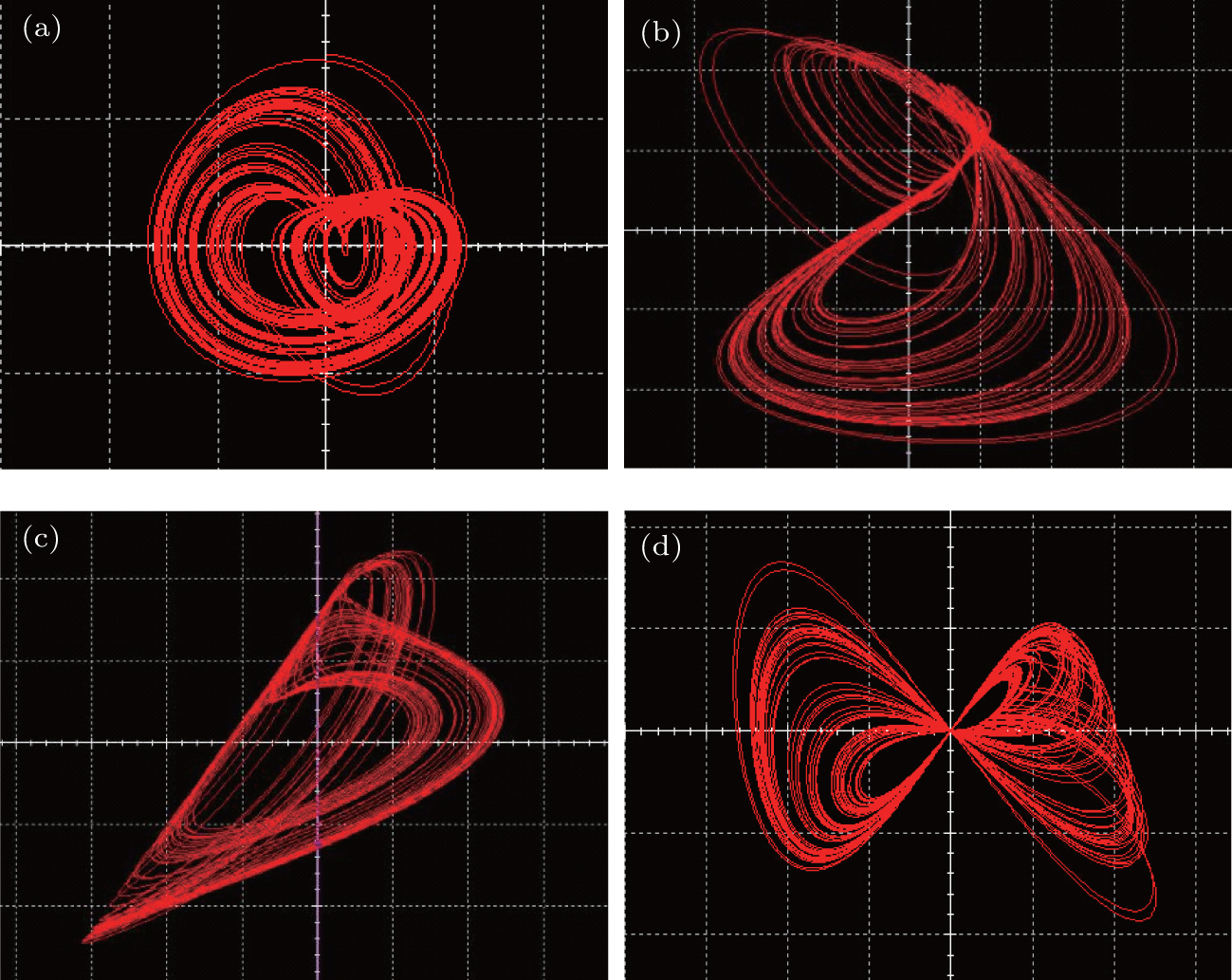
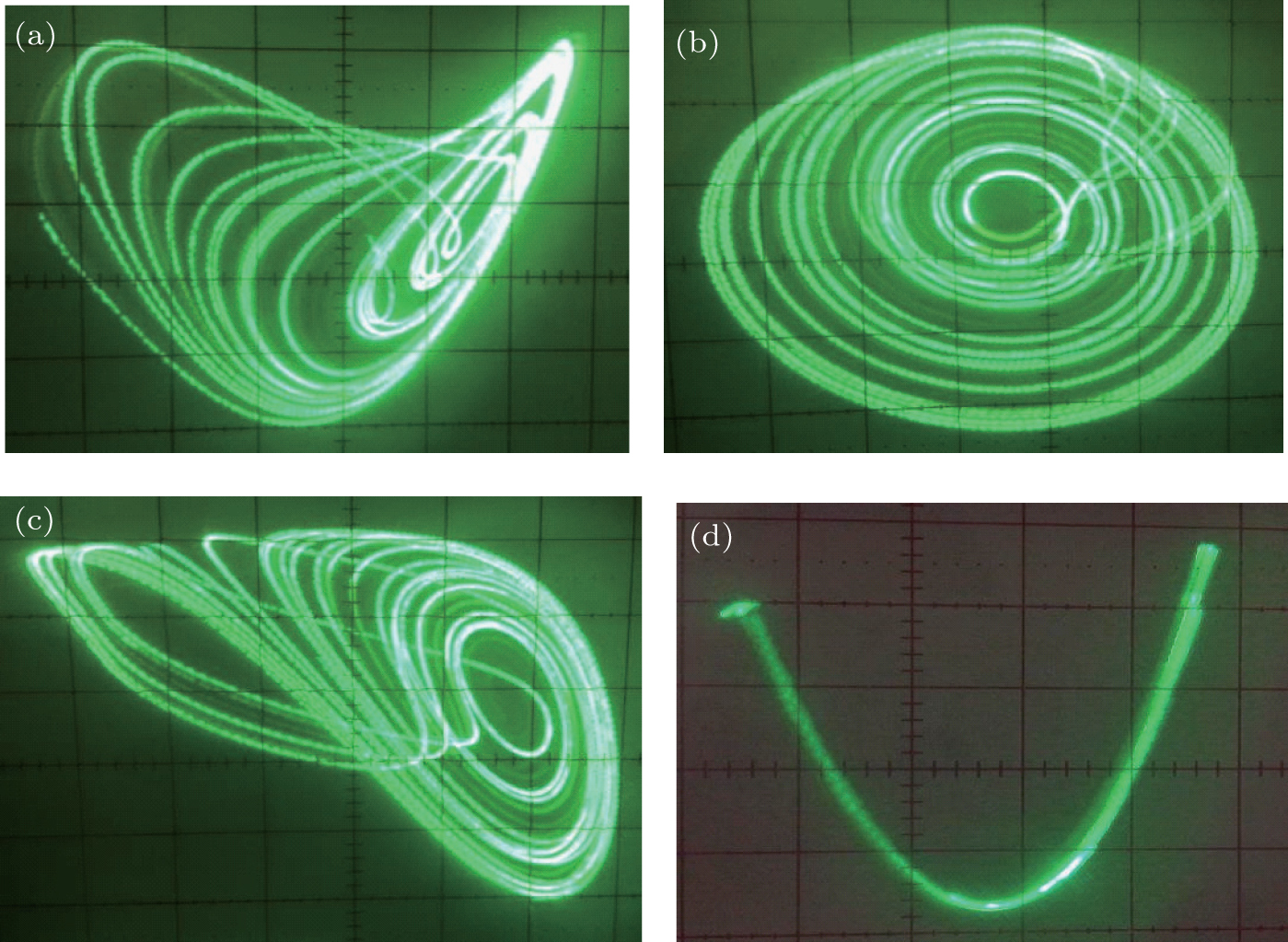 | Fig. 22. Experimental results of memcapacitor-based oscillator: (a) σ m – φ c phase diagram, (b) φ c – q L phase diagram, (c) σ m – q L phase diagram, (d) σ m – φ m phase diagram. |
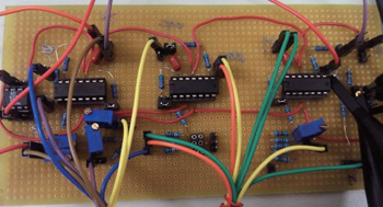
 | Fig. 23. Experimental circuit board for memcapacitor-based oscillator. |
The significance of the experiment with these charge-controlled memcapacitor circuits is that those circuit variables which are originally observed and measured with difficulties, such as flux φ c in the linear capacitor, flux φ m in the memcapacitor, charge q L on the inductor, and σ m , are directly observed and measured in this experiment. Particularly, the σ m – φ m characteristic described by 
Now, we provide a scheme for digitally realizing the proposed charge-controlled memcapacitor oscillator. The reasons for digitally realizing this system are shown as follows. Firstly, the analog chaotic circuit and its synchronization are easily affected by the precisions of the circuit elements and matching of the circuit parameters. Secondly, the digital technology is the mainstream technology for the expected future applications of the memcapacitor oscillation. Thirdly, it is digitalized so that we can detect the random properties of pseudo random sequences generated from this oscillator.
The digital signal processing (DSP) technology is used to realize the charge-controlled memcapacitor system, since the DSP technology is the mainstream technique for digital signal processing at present. Furthermore, the system utilizing the DSP technology is more effective for the practical applications of both pseudo random sequence generation and chaotic information encryption/decryption processing. For this purpose, the iterative form of Eq. (
Utilizing the DSP evaluation board (ICETEK-VC5509-AE) and the software environment platform CCStudio-v3.3, we can solve Eq. (
A simple way to generate a binary sequence from the above solved chaotic real value signal is to use the following threshold function:
 | Fig. 24. Digital circuit experiment: (a) chaotic PN sequence digitalized from x , (b) waveforms of x and y , (c) chaotic phase diagram of x and y , (d) experimental setup. |
In this section, by using the NIST test suite, the randomness of the proposed memcapacitor oscillator is verified by testing its binary sequences.
The NIST test suite, the most authoritative tool for pseudo-random testing currently, is a statistical software package consisting of 15 tests, which is developed to test the 757 randomness of binary sequences produced by pseudorandom signal generators. The 2.0 version of the test suite package is used in the experiment.
For a binary sequence of ‘0’ and ‘1’ of a given length n , the sequence is divided into k non overlapping parts with equal length m ( k = n/m ), here n = 1000000000 and m = 1000, so k = 1000000.
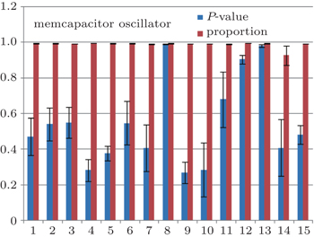
A final analysis report is generated for each test from the test suite package with relevant intermediate values, including test statistics (proportions) and P -values for each test. In order to compare with the well-known Lorenz system, a conclusion describing the quality of the sequences can be obtained by four tests based on these P -values and proportions, shown in Tables

| Table 1. Test report of the memcapacitor oscillator. . |
| Table 2. Test report of the Lorenz oscillator. . |
The distribution of P -values is used to examine uniformity. A P -value is calculated from


If P − value T ≥ 0.0001, the sequences can be considered to be uniformly distributed. From Table
If a value of proportion falls outside the interval defined by 
From Tables
 | Fig. 25. Sequence of the memcapacitor oscillator. |
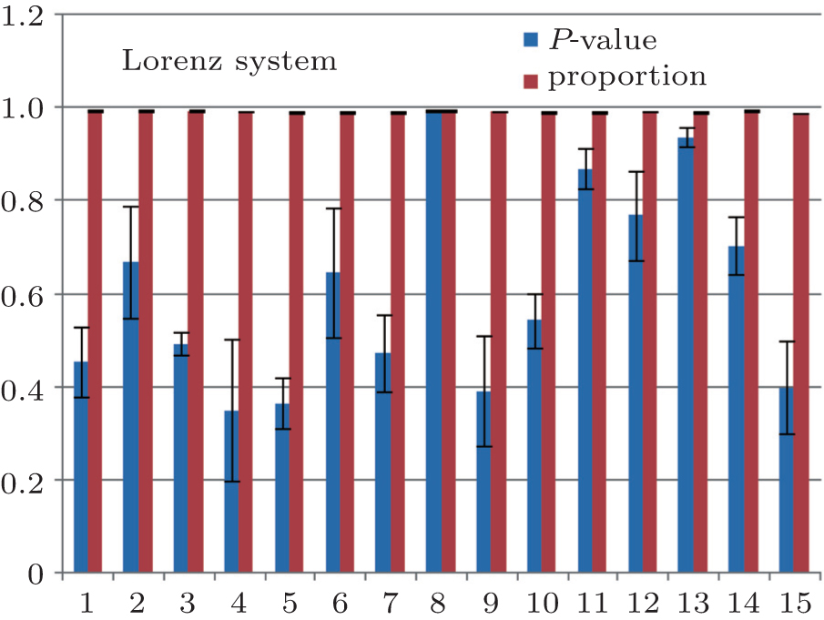 | Fig. 26. Sequence of the Lorenz oscillator. |
We design a mathematical model of the charge-controlled memcapacitor and its equivalent circuit for future advance studies of memcapacitor. On the basis of this model, a memcapacitor-based oscillator circuit is designed and realized. Theory analysis and experiments show that this oscillator possesses complex dynamical characteristics, such as sustained chaos with constant Lyapunov exponents, burst chaos, and novel irregular bifurcations. Moreover, a digital realization of the oscillator is given by using the DSP technology and the chaotic PN sequence is obtained. Random properties of the PN sequence fully meet the NIST standard, and therefore the proposed memcapacitor oscillator can be used for designing PN sequence generators as a new random signal seed.
| 1 | |
| 2 | |
| 3 | |
| 4 | |
| 5 | |
| 6 | |
| 7 | |
| 8 | |
| 9 | |
| 10 | |
| 11 | |
| 12 | |
| 13 | |
| 14 | |
| 15 | |
| 16 | |
| 17 | |
| 18 | |
| 19 | |
| 20 | |
| 21 | |
| 22 | |
| 23 | |
| 24 | |
| 25 | |
| 26 | |
| 27 |