1. IntroductionThe BaF2 process including the metallorganic solution deposition (MOD) and physical vapor deposition has been demonstrated being successful in manufacturing c-axis textured YBa2Cu3O7− δ (YBCO) superconducting films. The growth mechanisms were studied by a number of groups theoretically and experimentally and the solid– gas reaction-diffusion model was established and admitted by researchers.[1– 3] For the nucleation mechanisms, however, there are still issues that remain unclear.
Due to a lack of information about the elementary reactions, the supersaturation (Δ μ ) for YBCO nucleation was previously deduced from the overall reaction

with the form of  where Δ μ 0 reflects the free energy difference between the solid phases (i.e., precursor and YBCO)
Because the growth is strongly affected by the partial pressure of hydrogen fluoride (PHF), this reaction was believed to be highly reversible and the reaction kinetics was thought to be controlled by HF diffusion on the interface between the precursor and the gas flow. Assuming that the reactions and the diffusion in the precursor are in equilibrium, calculation for the growth rate can be made based on the solid– gas diffusion-reaction model, [2] which is proportional to the square root of water partial pressure (PH2O). This calculation fits the experimental data.[4] So we believe this model provides a good description of the growth rate. However, if we consider the prior stage for YBCO formation, in other words, the nucleation, there are unclear issues as addressed below.
First, the overall reaction (1) failed to reflect the intermediate phases which were observed and discussed.[2, 5, 6] Some of the intermediate phases are involved in the main reaction path and the others are the products of competing reactions. Considering that the supersaturation for nucleation should be defined by the free energy difference between YBCO crystal and the phases directly producing it, the overall reaction is not appropriate for the calculation of Δ μ . Therefore, a detailed reaction path is needed to determine the supersaturation.
Second, the diffusion equilibrium in precursor film generally requires the following relation:[7]

where JH2O, z and JHF, z denote the gas flow rates in the normal direction of the substrate. On the surface of the precursor, water vapor diffuses into the film while HF diffuses out, it can be inferred from Eq. (2) that PH2O near the substrate is expected to be lower than on the precursor surface and HF partial pressure is higher near the substrate. Under this condition, if YBCO is the reactant of a backward reaction, there should be more YBCO near the upper surface than the substrate to maintain reaction equilibrium, which contradicts with the experimental fact that YBCO nucleation and growth starts from the substrate. YBCO being the reactant of the backward reaction means that the nucleation and growth driving force is the deviation of gas pressure from reaction equilibrium, but the contradiction mentioned above negates it. The overall reaction (1) is therefore inadequate for nucleation analysis.
Furthermore, according to the classical theory of nucleation, the nucleation rate is expressed as[8]

where K is a coefficient related to temperature and the characteristic of the material, Δ G* is the maximum free energy necessary for nucleation formation, q is the energy of activation for diffusion across the phase boundary, and n is the number of nucleus per unit volume. If the nucleation occurs in the solid phase, q would be extremely large. Considering that the film growth rate in MOD is as high as nanometers per second which is comparable to the methods with observable liquid (10 nm/s), [9] we suggest that there should be a state with high diffusivity such as the liquid phase in the BaF2 process. This notion was also expressed as “ quasi-liquid” by Araki et al.[3] and Holesinger et al.[10]
2. Methods and experimentsTo introduce our description of the process, an oxide eutectic liquid phase “ L” should be presented which, we consider, is critical to the nucleation. As the size of a material is very small, the surface energy plays an important role in phase transition. Thus small liquid drops can exist when the temperature is lower than the bulk melting temperature. In fact, this is a general phenomenon called the size effect, having been demonstrated by several groups for both pure material and eutectics, and the relation between the melting temperature and particle size can be approximately written as[11, 12]

where Tm is the melting temperature of a small piece of substance, Tb is the bulk melting temperature of it, ε is a constant describing the characteristic of the material, γ is a geometry factor, ρ is the density, and m is the mass. At a certain temperature point Tm, this effect limits the size of a liquid drop below a definite value mmax which is deduced from Eq. (4)

In the phase diagram of the Y– Ba– Cu– O eutectic system, the lowest eutectic temperature belongs to Ba– Cu– O with Ba:Cu near 3:5.[13] Considering that this eutectic is often used as a solvent in the liquid phase epitaxy method and the nucleation temperature in the BaF2 process is low compared with other preparation methods without BaF2, it is the most possible liquid phase in the BaF2 process. The experiment results discussed later further confirm this.
Regarding that the size effect is a surface phenomenon, the contact between the liquid drop and its environment is important. It is well known that the wetting of Ba-Cu-O eutectic liquid on the substrate for a YBCO coated conductor is good, which means lower surface energy, so at the same temperature, the size of the liquid drop is larger at the substrate. As a matter of fact, the transient liquid is not a new concept in the general theory of sintering.[14] When HF is present in the precursor, a certain total amount of liquid phase as the product of the reaction can exist under the reaction equilibrium, but each single liquid drop is transient due to the backward reaction.
On the other hand, we write Ba(OxFy)2 instead of BaF2 as the starting material in this work, this is base on other researchers’ experimental results and microscopic observations.[5, 15] Wong et al.[16] demonstrated that when BaF2-Y film, BaF2-Cu film, and BaF2 film react with H2O gas respectively, the final products consisted of only Ba(OxFy)2, Y2O3, BaCuO2, and CuO, and no further reactions occur, that means that if there is no YBCO produced, F will not be completely removed by the reaction. This phenomenon suggests that YBCO crystal growth is a product removing process rather than being a reactant of backward reaction. That is to say, in the upper part of the precursor film, higher PH2O and lower PHF only mean that the amount of the intermediate phases, with which HF reacts, is larger. So the contradiction mentioned above no longer exists.
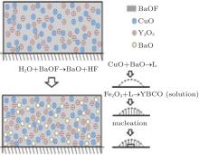
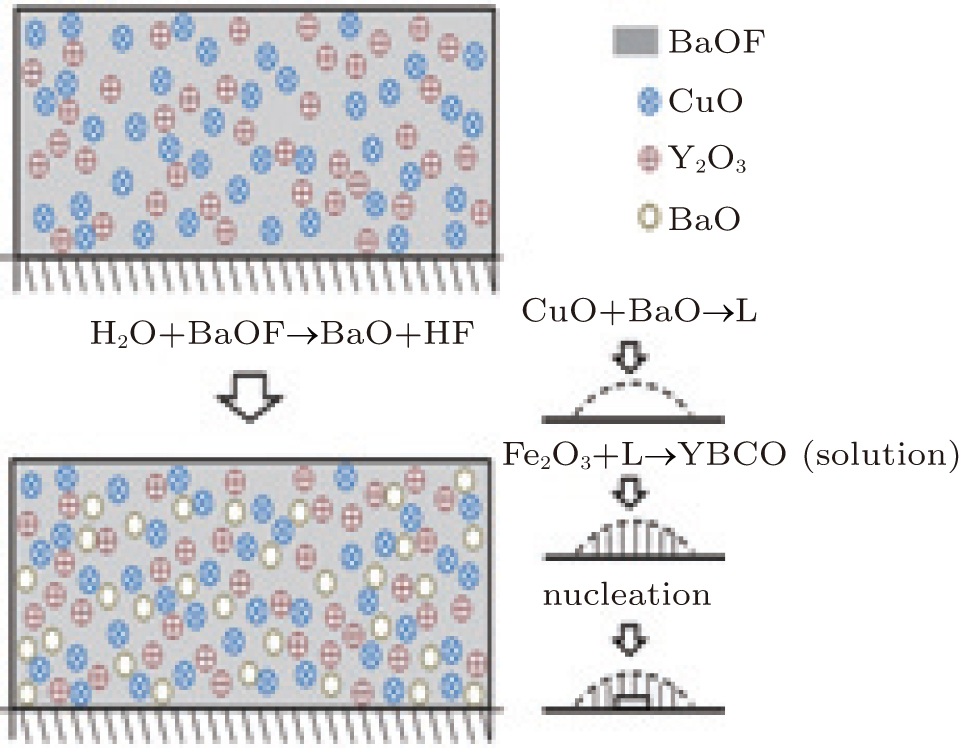
Based on the Ba– Cu– O transient liquid, we propose a reaction path


The process can be described as follows and illustrated in Fig. 1. Ba(OxFy)2 reacts with H2O producing BaO and HF, BaO, and CuO produce small-size eutectic liquid drops, then Y2O3 contacts and reacts with the liquid phase to produce YBCO as a solute which dissolves into the liquid. When the YBCO concentration is high enough, it precipitates on the substrate. The oxide eutectic liquid reacts with HF at the same time, which is the inverse of the process, this is the reason why the YBCO growth is sensitive to HF, but reactions (9) and (10) suggest that the direct nucleation driving force is the supersaturation of YBCO in the liquid drops instead of fluctuation of HF partial pressure. Noticing that there is a liquid phase in this model, the diffusivity needed for textured crystallization is satisfied, and the shrinkage at relatively low temperature (973 K) and accompanied by F removal can be partly explained.[6]
In order to analyze the thermodynamics of nucleation, we divided the system into three subsystems, i.e., precursor and gas, intermediate oxide eutectic, and then solid YBCO. The nucleation occurs in the liquid phase. Considering that the forward reaction produces the liquid while both the nucleation and the backward reactions consume it, the total mass of the oxide liquid drops is in dynamic equilibrium. Because the liquid drops are small, the thermodynamic relaxation time is short, so every liquid drop is expected to be in statistical equilibrium at any moment. Considering each single liquid drop is transient, we should notice that nucleation of YBCO cannot occur unless the liquid drop’ s life is longer than the character time of nucleation.
Classical solution model was applied to approximately describe the liquid drops. To simplify the calculation, we assumed that the shape of the liquid drop on the substrate is a spherical crown, setting r to be the bottom radius, θ to be the wetting angle, the surface area of the spherical crown is

The volume is
The amount of HF reacting with liquid drop per unit time on unit area is

The dependence between r and time can be represented as
where M is the formula weight of Ba– Cu– O eutectic, ρ is the density of the liquid phase, kY is the amount of Y2O3 contacting and reacting with liquid drop per unit time on unit area, and b is the balancing coefficient of BaO in reaction (6).Solve Eq. (14), set

and r0 to be the maximum radius at a certain temperature, we obtain

Therefore, the life of a single liquid drop is

While the character time of nucleation can be approximately expressed as

Here, Δ t should be larger than τ . For the liquid drop far from the substrate, where Δ G* is much larger, this condition can hardly be satisfied in common treatment condition, so nucleation mostly occurs on the substrate where the liquid drop is large enough and Δ G* is relatively small.
According to the calculation and experiments performed by Granozio et al., pure c-axis nucleation occurs at lower supersaturation.[17] On the contrary, at higher supersaturation, a-axis nucleation begins and then surpasses c-axis nucleation. In solution, the superaturation of solute can be written as

where c* is the solubility of YBCO in Ba– Cu– O oxide eutectic in the unit of mole per volume.
Since the concentration of YBCO can be calculated as

suppose interval [c1, c2] to be the pure c-axis nucleation region, then the corresponding time interval will be
The possibility of nucleation in this interval is

where
Substituting Eqs. (3), (12), and (15) into Eq. (20), we obtain

We can also rewrite Eq. (21) in the form of
In Eq. (22), for certain YBCO concentration c, Δ G* is definite because it only depends on c, the other part of the integral will decrease with increasing H. That is to say, the possibility of pure c-axis nucleation reduces with increasing PHF.
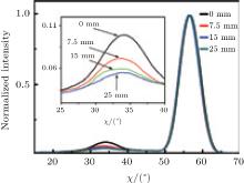
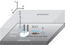
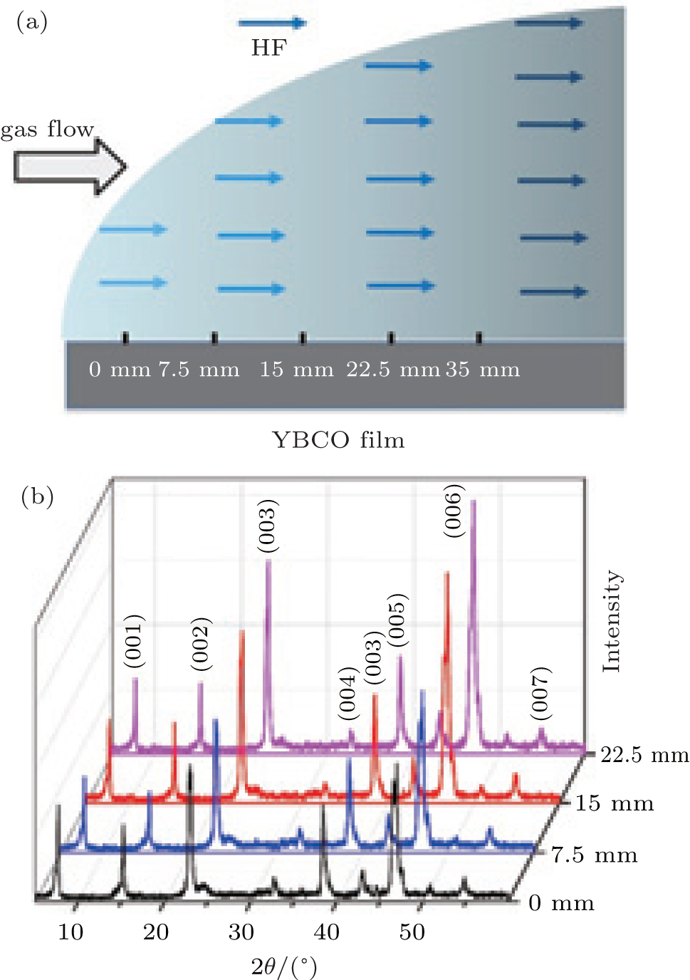
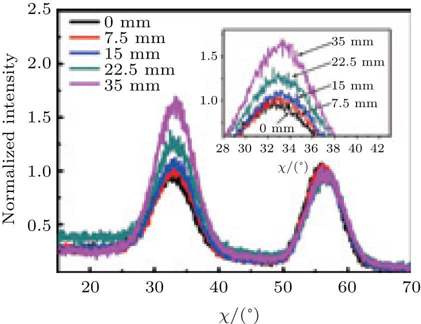
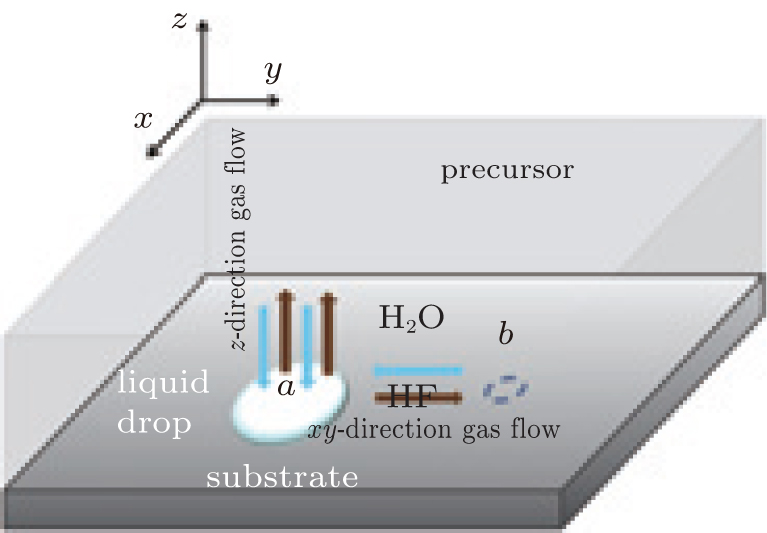
To demonstrate this result, we prepared a 10-cm long YBCO tape by the metal– organic method. Pyrolyzed film was heated from room temperature sharply up to 770 ° C and H2O was not provided before 770 ° C to avoid low temperature nucleation. The gas flow direction was along the tape length as illustrated in Fig. 2(b) making PHF downstream higher while other parameters were nearly the same. In Fig. 2(b), the θ – 2θ scan result is shown. Since the θ – 2θ scan result is comprehensive which can be influenced by many factors like grain size, O content, etc., we chose the χ scan to manifest the grain orientation for clarity. Figure 3 shows the normalized χ scan result of the YBCO (102) plane at different locations. The peak at about 33° presents a-axis nucleation while the peak at about 57° presents c-axis nucleation. The portion of a-axis can be calculated by[17]

Figure 3 shows that the a-axis portion downstream is higher than upstream even though the reaction rate downstream is low, this supports our conclusion.
Up to now, we have proposed our model for nucleation in the BaF2 process. As applications and checks of validity, we will analyze the effects of processing parameters such as the temperature ramp and oxygen partial pressure on nucleation, as well as the secondary phase segregation and nucleation density. All these phenomena are commonly observed and important for manufacturing of the YBCO coated conductor.


 ]
]