

Microflow-induced shear stress on biomaterial wall by ultrasound-induced encapsulated microbubble oscillation
[Hu Ji-Wena), b) , Qian Sheng-You†b)  , Sun Jia-Na
a) , Lü Yun-Bina) , Hu Pinga) ]
, Sun Jia-Na|
|


†Corresponding author. E-mail: syqian@foxmail.com
*Projects supported by the National Natural Science Foundation of China (Grant Nos. 11174077 and 11474090), the Natural Science Foundation of Hunan Province, China (Grant No. 13JJ3076), the Science Research Program of Education Department of Hunan Province, China (Grant No. 14A127), and the Doctoral Fund of University of South China (Grant No. 2011XQD46).
A model of an ultrasound-driven encapsulated microbubble (EMB) oscillation near biomaterial wall is presented and used for describing the microflow-induced shear stress on the wall by means of a numerical method. The characteristic of the model lies in the explicit treatment of different types of wall for the EMB responses. The simulation results show that the radius-time change trends obtained by our model are consistent with the existing models and experimental results. In addition, the effect of the elastic wall on the acoustic EMB response is stronger than that of the rigid wall, and the shear stress on the elastic wall is larger than that of the rigid wall. The closer the EMB to the wall, the greater the shear stress on the wall. The substantial shear stress on the wall surface occurs inside a circular zone with a radius about two-thirds of the bubble radius. This paper may be of interest in the study of potential damage mechanisms to the microvessel for drug and gene delivery due to sonoporation.
Much work has been reported on encapsulated microbubble (EMB) expansion and collapse near a confining surface, especially for the problem of cavitation damage.[1– 3] Under the ultrasound-induced interactions between microbubbles and cell membrane of the vessel wall, a phenomenon known as sonoporation is currently under active study as a promising technique for drug and gene delivery.[4, 5] However, the mechanisms to produce sonoporation are very complicated, and remain a challenge for the development of sonoporation-mediated applications. Two dominant hypotheses have been reported for explaining this process. One of the suggested mechanisms of sonoporation is linked to inertial cavitation during the collapse of microbubbles. This process leads to the generation of shock waves and microjets that may pierce and permeabilize cell membranes[6, 7] and induce inhomogeneous cyclic pressure fields that create eddy currents in the fluid surrounding the microbubble, which conversely exerts stress on nearby cell membranes.[8– 10] However, thess bioeffects by inertial cavitation are not easily controlled and usually cause non-reparable injury.[11, 12]
Another hypothesis is due to stably oscillating (non-inertial cavitation) microbubbles that can also generate sonoporation by acoustic microstreaming.[13, 14] The microstreaming, which occurs near pulsating microbubbles, induces a fluid shear stress on neighbouring vessel walls or cell membranes.[8, 14] Experiments also showed that shear stress gradients with sign reversals can lead to the disruption of endothelial cell membrane integrity and functionality, [15] and the reparable sonoporation can be observed under the stably oscillating microbubble.[16] However, to safely use microbubbles for sonoporation, it is important to understand the mechanisms involved and estimate the mechanical effects due to microbubble oscillation on the nearby cell membrane. Nyborg[17] proposed an approximate method for estimating acoustical microstreaming and the shear stress induced on a surface by the oscillations of a microbubble. On this basis, Lewin and Bjorno[13] calculated a simplified case of a hemisphere microbubble attached to the surface, and claimed that even the low-intensity diagnostic ultrasound is capable of producing such high shear stress to induce microalterations in living tissue. However, Nyborg’ s method was not applied to a bubble detached from the surface. Based on the solution of Laplace’ s equation and by using a boundary intergral method, Krasovitski and Kimmel[18] provided the evolution of the bubble shape together with the velocity and potential fields on the bubble surface, and evaluate the microstreaming shear stress on the plane wall. However, they do not evaluate the effect of wall types and the bubble-wall distances to the shear stress.
Many previous models of ultrasound-driven EMB response are based on a modified Rayleigh– Plesset equation that has been derived for a free microbubble resting on a rigid plane, where the so-called method of images is applied for the analysis of the EMB response.[19, 20] In this paper, a modified EMB model is given for describing the influences of different types of wall to the EMB dynamics. Two main goals in this paper are: (i) to test the model of bubble-wall interaction solutions, which compares theoretical predictions with other models and experimental measurements; (ii) to study sonoporation for calculating the microstreaming velocity and shear stress on the wall. Finally, we summarize our studies.
Many studies have shown that the proximity of a boundary can produce considerable changes in the oscillation amplitude of EMB and its scattered echo.[20– 22] In this study, we use a modified model for treatment of different types of wall for the EMB response. Therefore, some assumptions are given first: i) the EMB remains spherical in liquid at all times; ii) the EMB undergoes radial pulsation with no translation; iii) the bubble approximates to a linear oscillator when driven at low amplitude; and iv) the plane wall keeps no deformation for the solid materials with much greater elastic modulus.
For a free oscillation EMB in an infinite homogeneous liquid, the scattered pressure at the distance r from the EMB center can be expressed as[23]
where R and Ṙ are respectively the radius and radius velocity of the EMB. When the scattered wave reaches a boundary, a portion of the wave undergoes reflection and a portion of the wave undergoes transmission across the boundary. If the boundary wall is rigid, the scattered pressure, Psca, is totally reflected by the wall. Reflection of the scattered waves off the wall can lead to an additional pressure on the surface of the EMB. Thus, the additional pressure surrounding the EMB can be expressed as

where Zr represents the sound reflection coefficient of the boundary wall and is defined as three types of wall,
To obtain the scattered pressure of EMB near the wall, the equation of the EMB dynamics must be solved. To this end, a model for describing the dynamics of an EMB confining a plane wall is shown in Fig. 1. In an infinite homogeneous Newtonian liquid, the dynamics of a microbubble can be described by the following Keller equation:[24]
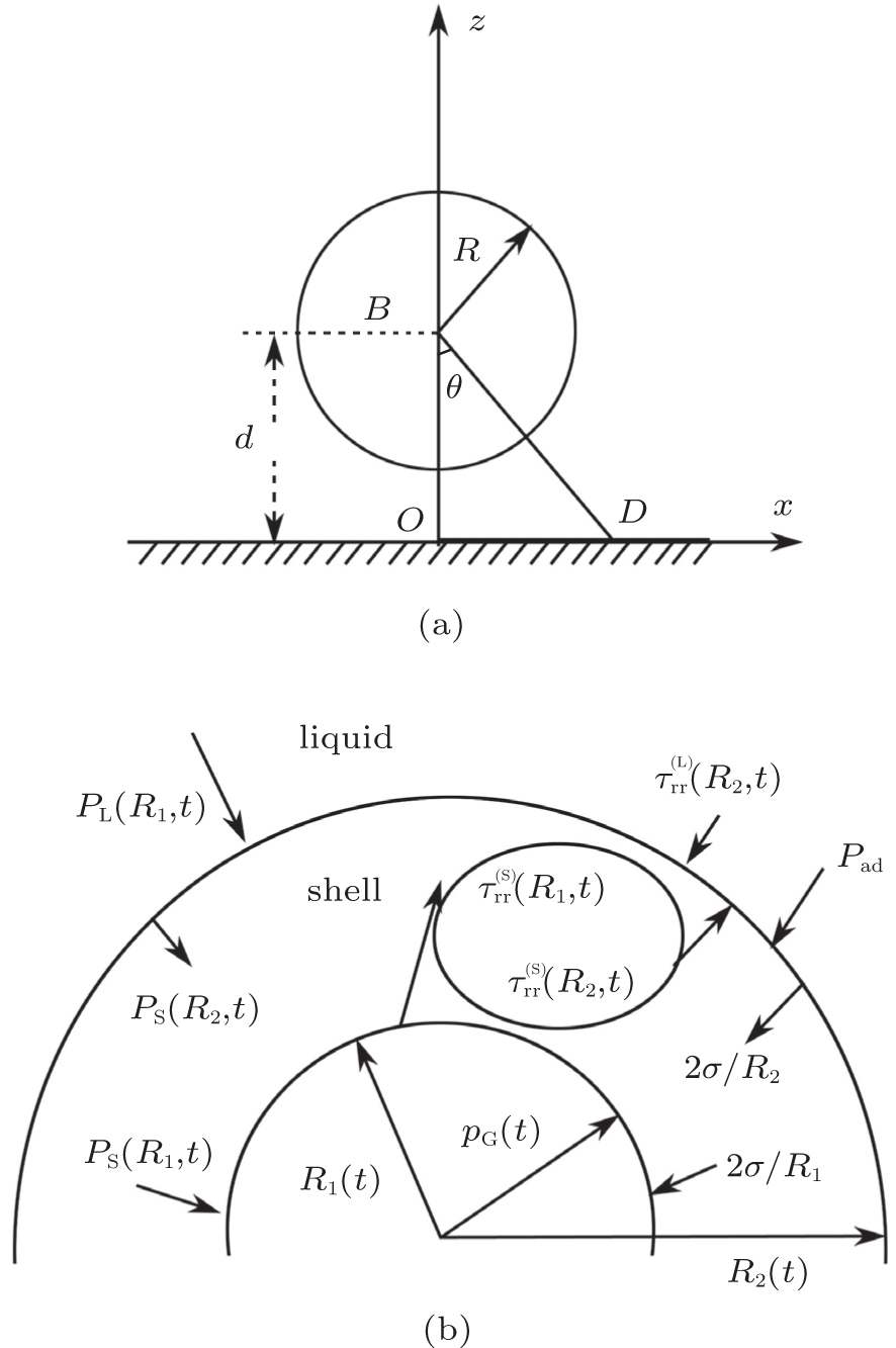 | Fig. 1. Schematic sketch of a bubble near a plane wall (a) and the forces on the gas EMB surface (b). |

where PL is the pressure at the bubble surface, PI is the pressure at infinity, and Ṗ G denotes a time derivative of gas pressure within the EMB. The gas pressure is given by[24]
where P0 is the hydrostatic pressure, σ 1 and σ 2 are respectively the surface tension of the inner and outer of EMB wall, γ is the polytropic index, while b and Vm are the van der Waals constant and the universal molar volume, respectively. When an EMB is close to a plane wall, the sound pressure should include the influence of the reflected pressure because of the scattering of EMB oscillation. Following Yang and Church, [25] the term (PL(R, t) – PI(t)) in Eq. (4) can be obtained and given by

The radial component of the stress tensor τ rr can be represented as

where G is the shear modulus of EMB wall, μ is the viscosity of liquid, ε r and 
where 
Assuming that the pulsation amplitude is small, that is R1(t) = R10(1 + x(t)) and 
where ω ∞ denotes the resonance frequency in an unbounded fluid, and α is

In a cartesian coordinate system, xoz, as shown in Fig. 1(a), the x component of micro-streaming velocity, Uax, induced on the plane wall by the pulsating EMB can be obtained as

where the distance between points B and D is BD2 = x2 + d2, and the gradient of velocity Uax is
According to Nyborg’ s theory, [17] the x component of shear stress exerted on the plane wall can be approximately expressed as

where μ L is the coefficient of shear viscosity of the liquid. The parameter, δ , can be calculated from the expression given by Lamb[26]

where fd is the driving frequency of external pressure. Equations (4) and (9) provide the desired formulation describing the dynamics of the EMB confined nearby a plane wall, and the microstreaming velocity and shear stress on the plane wall can be calculated through Eqs. (12) and (14).
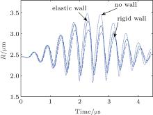
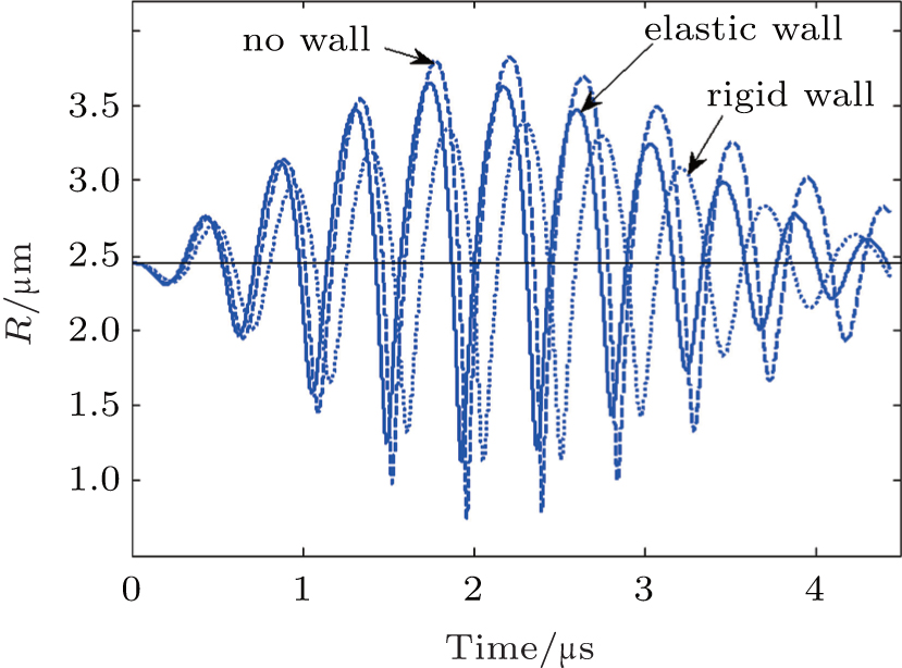
To obtain a prediction for the shear stress exerted on a plane wall, we present a numerical simulation which has been made using Eqs. (4) and (9) in the parameters range of interest for medical ultrasound application. The simulations are conducted by the computing software Matlab (Mathworks matlab R2009a). We first validated our model by comparing it with the estimates of other investigators by using the parameters of Table 1. The EMB is insonified with an 8-cycle, 200 kPa, 2.25 MHz Gaussian pulse, and the parameters of the shell property come from Qin et al.[27] The radius-time curves obtained are presented in Fig. 2. The dotted line represents the curve for the bubble in a borderless liquid (Zr = 0), the solid line corresponds to the bubble near an elastic wall (Zr = 0.6), and the dashed line shows the curve for the bubble near a rigid wall (Zr = 1). One can see that, compared to that of the case with no wall, the maximum oscillation radius decreases as the EMB near the elastic and rigid wall. These radius change trends by our model are consistent with the results in Refs. [19] and [28], in which the oscillation of an EMB is insonified with a Gaussian pulse nearby three different walls. Garbin et al.[22] have reported that the vicinity of the wall can suppress the amplitude of the EMB oscillation. That is, the tendency predicted by our theory can produce the same change with the existing models and experimental results.
| Table 1. Material properties applied in simulation. |
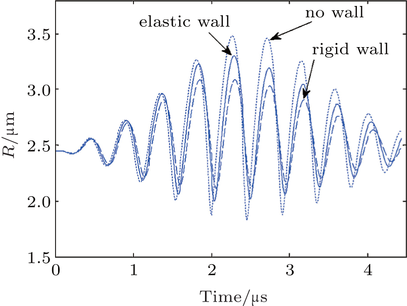 | Fig. 2. Comparation of the radius-time curves for a 2.45-μ m radius bubble insonified with an 8-cycle, 200 kPa Gaussian pulse for the EMB– wall distance of ds = 1.0R20. |
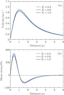
We next apply our model to calculate the distributions of streaming velocity and shear stress on a plane wall. However, it is worth noting that Nyborg’ s theory is just for small amplitude oscillations. The following calculation is in compliance with this theory. Hence, an EMB with an outer radius of R0 = 1.5 μ m is insonified with an 8-cycle, 200 kPa, 2.25 MHz sine pulse, and is used for calculating the microstreaming velocity and shear stress under the expansion phase of the EMB oscillation. Figure 3(a) illustrates the velocity distribution along the x axis for three different Zr for the EMB-wall distance of d = 1.0R0. The velocity first rises and then drops. The maximum streaming velocity on the wall decreases from 1.03 to 1.11 m/s with Zr increasing from 0.2 to 1.0. The shear stresses on the wall have the same change as Zr when the distance x is less than 1.5 μ m. Here, the positive and negative shear stresses correspond to the positive and negative velocity gradient, respectively. As seen from Fig. 2(b), the maximum shear stresses are respectively 173, 164, and 152 Pa corresponding to three sound reflection coefficients, that is, 0.2, 0.6, and 1.0, and tends to be 0 after 5.0 μ m.
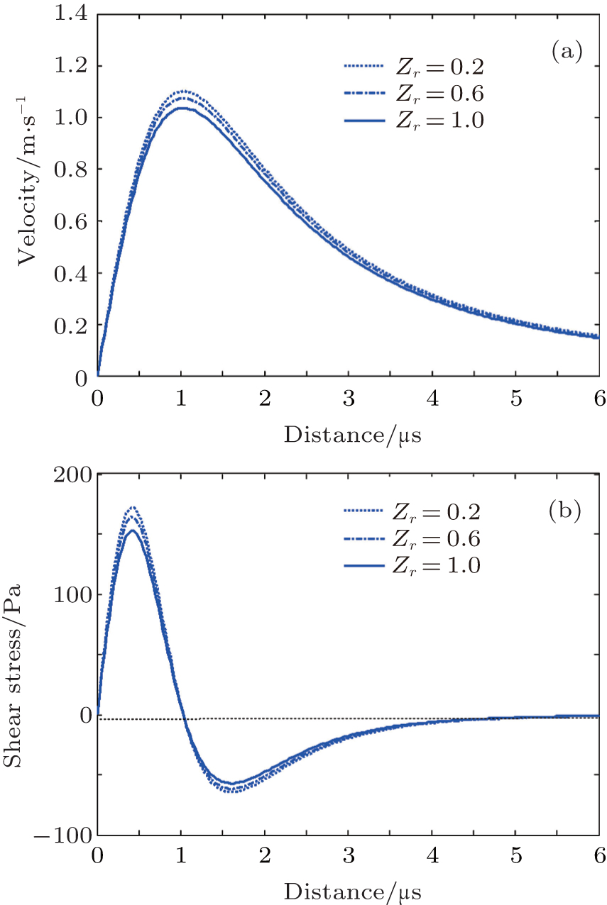 | Fig. 3. The distributions of microstreaming field under the expansion phase of EMB for three reflection coefficients and a radius of R0 = 1.5 μ m and the EMB– wall distance of d = 1.0R0. (a) The maximum velocity curves; (b) the maximum shear stress curves. |
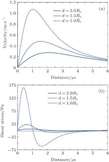
The presence of a wall not only influences the radial oscillation of an EMB, but the acoustic pressure field in the ambient liquid induced by the wall should be changed with increasing/decreasing EMB– wall distance as seen in Eq. (9). This statement is confirmed in Fig. 4, which illustrates the curves of microstreaming velocity and shear stress for three EMB– wall distances and a reflection coefficient of 0.6. These curves have the same change trend as in Fig. 3. However, the maximum velocity and shear stress substantially decreases with the EMB– wall distances increasing from 1.0R0 to 2.0R0. For example, the maximum shear stress decreases from 164 to 24 Pa as the EMB– wall distance increase from 1.0R0 to 1.5R0. Figure 4 suggests that the EMB– wall distance has an important influence to produce sonoporation. This observation is consistent with previous work.[18– 20, 29]
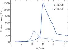
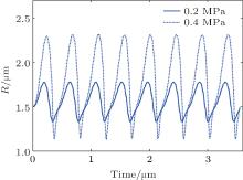
Finally, the effect of an initial radius of EMB ranging from 0.5 to 5.0 μ m on shear stress is examined. Figure 5 shows the shear stress as a function of R0 when the amplitude of the acoustic field is 0.2 MPa. The shear stress increases from 4.2 to 342 Pa with R0 increasing from 0.5 to 2.2 μ m for 2 MHz, and from 3.7 to 1200 Pa with R0 increasing from 0.5 to 3.0 μ m for 1 MHz, respectively. Figure 5 also illustrates that 2 MHz ultrasound generates higher shear stress than 1 MHz ultrasound in the radius range between 0.5 and 2.2 μ m. A similar shear stress distribution is obtained or observed in Refs. [29]– [32] for the case of non-inertial cavitation.
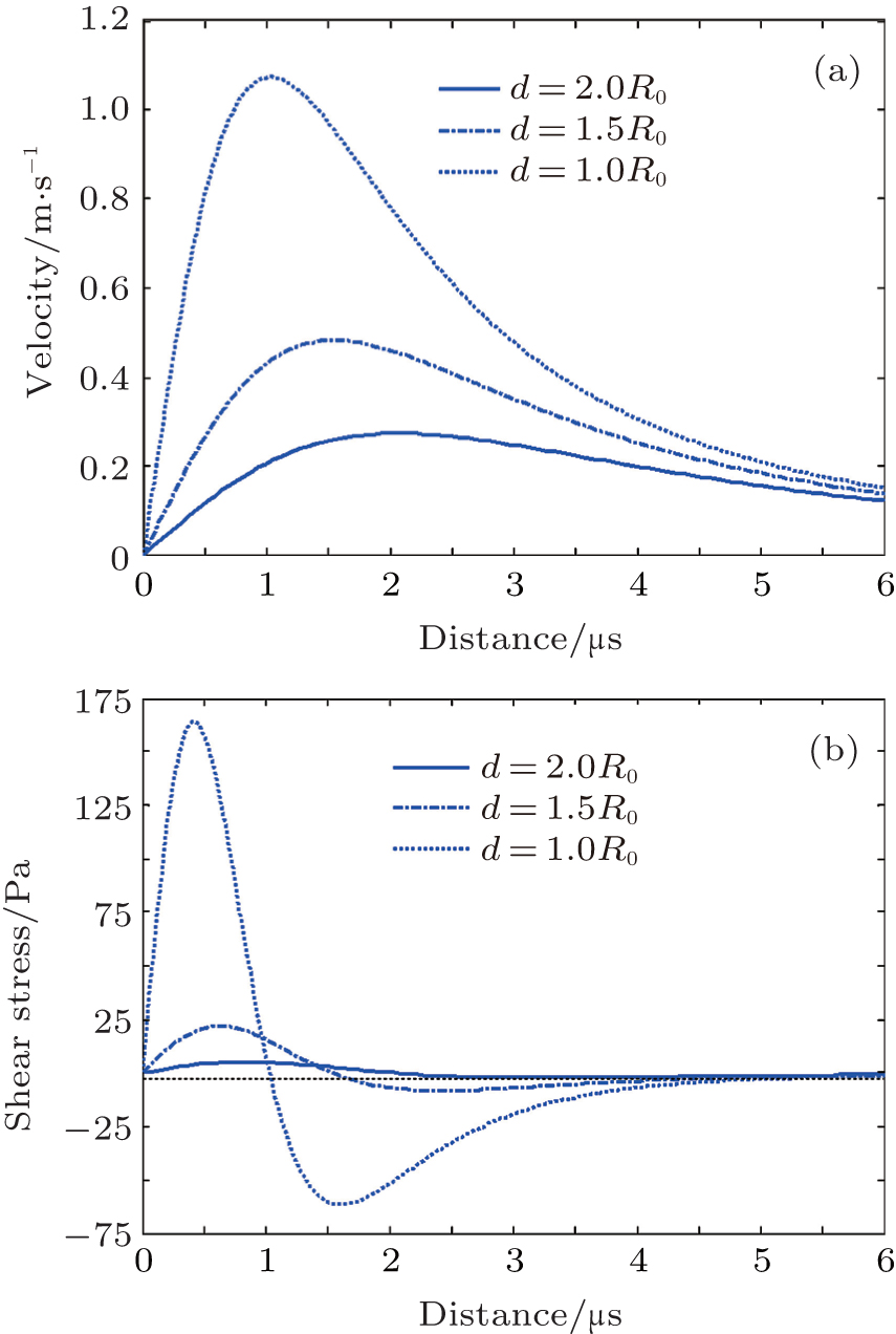 | Fig. 4. Distributions of microstreaming field under the expansion phase of EMB for three EMB– wall distances and a reflection coefficient of Zr = 0.6 and a radius of R0 = 1.5 μ m. (a) The maximum velocity curves; (b) the maximum shear stress curves. |
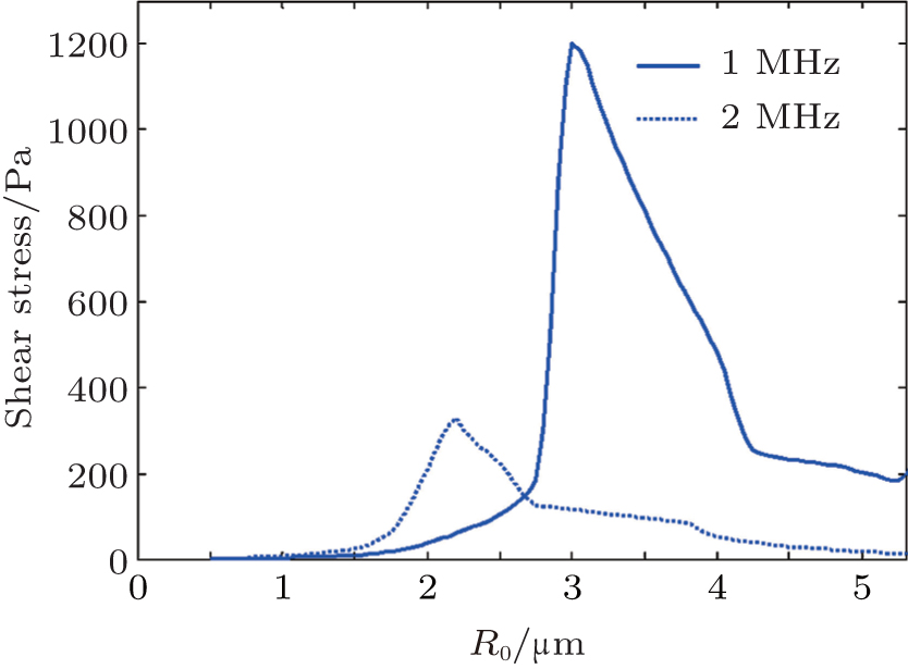 | Fig. 5. Shear stress versus radius generated by an EMB under its expansion phase when p = 0.2 MPa for an EMB– wall distance of d = 1.2R and a reflection coefficient of Zr = 0.6. |
Figures 3 and 4 indicate that substantial shear stress on the surface occurs inside a circular zone with a radius about two-thirds of the bubble radius, and it is focused on the half of the bubble radius in Ref. [18]. This small difference of the shear stress distribution may be related with the method of the deduced dynamic equation.
In addition to the influence of the factors above, wall material properties, such as density, bulk modulus and shear modulus, etc, also have an important influence on the shear stress according to Doinikov et al.’ s model.[19] They described the percentage of cells undergoing sonoporation and the sonoporation efficiency at different values of driving frequency and acoustic pressure. Their shear stress distribution created by oscillating microbubble on the cell membrane has the same change as ours. However, many parameters of cell wall are specified to determine the dynamics of EMB during bubble-wall interaction in their model. If we let Zr = − 0.5 and use the simplified zero-thickness shell bubble applied in Ref. [28], a similar change of radius– time curve to the results in Ref. [28] can be obtained, as shown in Fig. 6. It seems reasonable to only consider the influence of reflection of sound by interface in describing the EMB response. Under the ultrasound-induced interactions between microbubbles and cell membrane of the vessel wall, the asymmetry of the bubble increases with pressure amplitude[29, 33] and has an influence on the pressure of the liquid.[34] However, in the case of weak pulsations, the shape of the bubble remains close to a sphere.[18] Using the parameters in Table 1, the EMB vibrates in a quasi-harmonic approximation, as shown in Fig. 7. The pressure amplitude is 1.765 μ m at a pressure of 200 kPa and meets the demand of Nyborg’ s approximation.[17]
 | Fig. 6. Comparation of the radius-time curves with a simplified zero-thickness shell bubble used in Refs. [19] and [28] with acoustic parameters in Fig. 2 for Zr = − 0.5. |
 | Fig. 7. Radius-time curves for a 1.5-μ m radius bubble insonified with an 8-cycle, 200 kPa sine pulse for the EMB– wall distance of d = 1.0R0. |
On the other hand, the bubble oscillation can induce the vessel wall dilation and depression under the external pressure field.[33, 35] Experiments showed that some biological objects have higher elastic modulus (such as lymphocytes), and can be seen as no deformation of wall.[36] However, other biological objects have much lower elastic moduli. Brujan investigated experimentally the interaction between cavitation bubbles and an elastic boundary, and found that the elastic modulus of the boundary did not exceed 2.03 MPa.[37] We have to admit that the main reason why we use the fourth assumption is that at present there is no theory for an elastic wall that could be incorporated into our calculations through the analytical method. Further theoretical development, including bubble cluster effects, [38] is required for consideration of these processes, and the presented arguments justify the use of the model of different walls for the cell membrane, at least as a first approximation.
A theoretical model for the dynamics of a hypothetical contrast agent confined surface is proposed for sonoporation. The simulation results show the tendency predicted by our theory can produce the same change as the existing models and experimental results for different type walls. For the EMB– wall interaction for producing sonoporation, it is found that the shear stress is greater on a plane wall for a larger bubble. Especially, the EMB– wall distance has an important influence to produce sonoporation. This model may be applied to investigate a bubble– cell interaction in order to evaluate the damage of cells undergoing sonoporation at different values of the acoustic parameters.
| 1 |
|
| 2 |
|
| 3 |
|
| 4 |
|
| 5 |
|
| 6 |
|
| 7 |
|
| 8 |
|
| 9 |
|
| 10 |
|
| 11 |
|
| 12 |
|
| 13 |
|
| 14 |
|
| 15 |
|
| 16 |
|
| 17 |
|
| 18 |
|
| 19 |
|
| 20 |
|
| 21 |
|
| 22 |
|
| 23 |
|
| 24 |
|
| 25 |
|
| 26 |
|
| 27 |
|
| 28 |
|
| 29 |
|
| 30 |
|
| 31 |
|
| 32 |
|
| 33 |
|
| 34 |
|
| 35 |
|
| 36 |
|
| 37 |
|
| 38 |
|